Powermat PM-220L-IMGS User manual

PM0698
ORIGINAL INSTRUCTIONS
USER MANUAL
PLACE OF MACHINE IMAGE HERE
Inverter Welder
PM-220L-IMGS
Synergy

2
TABLE OF CONTENTS
TABLE OF CONTENTS ................................................ .................................................. .................................................. .................... 2
SYMBOLS WARNING / INFORMATION .............................................. .................................................. .................. 4
PURPOSE OF THE DEVICE ................................................ .................................................. ........................................ 5
SAFETY ................................................. .................................................. .................................................. ........ 6
Safety during welding ............................................... .................................................. .............................. 6
General safety ............................................... .................................................. ............................. 8
Protection against electric shock .............................................. .................................................. ................... 8
Electromagnetic field ................................................ .................................................. ........................................... 9
Pacemakers ................................................ .................................................. .................................................. ....... 9
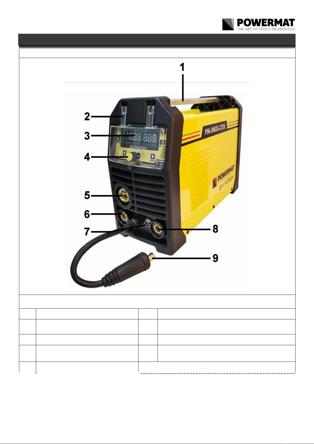
DESCRIPTION OF THE DEVICE ................................................ .................................................. .................................................. ....... 10
DESCRIPTION OF SYMBOLS ON THE LABEL ............................................. .................................................. ............. 12
TECHNICAL DATA ................................................ .................................................. .................................................. ...... 13
GENERAL WORKING CONDITIONS MACHINE ............................................. .................................................. ................... 13
General thoughts ................................................ .................................................. .................................................. .......... 13
Basic steps before you begin working ............................................. .................................................. ..... 14
During welding operations ............................................... .................................................. ..................................... 14
Prohibited Actions ................................................ .................................................. ............................................... 14
Basic activities after work ............................................. .................................................. ............. 14
Final remarks ................................................ .................................................. .................................................. ....... 15
USING THE MACHINE ................................................ .................................................. ............................................... 15
Connecting to the network ............................................... .................................................. .................................................. . 15
Inserting the wire electrode ............................................... .................................................. ............................... 15
Connection of protective gas ............................................... .................................................. ................................... 16
Welding MMA ............................................... .................................................. ............................................ 16
MAG welding in manual mode ............................................ .................................................. .............. 16
Welding by TIG-LIFT ............................................. .................................................. .......................................... 16
Welding wire holder magazine (spool gun) ......................................... .................................................. . 17
Control panel ................................................ .................................................. .................................................. ..... 18
BASIC INFORMATION FOR WELDING .............................................. .................................................. .. twenty
WELDING ELECTRODES IN PRACTICE .............................................. .................................................. ......................... twenty
Electric arc welding ............................................... .................................................. .................................. 21
Selection of appropriate electrode ............................................... .................................................. .................................. 21
Correct welding position ............................................... .................................................. ................................... 22
Tips arc ignition .............................................. .................................................. ............................... 22
Proper arc length ............................................... .................................................. ........................................... 23

3
The correct welding speed ............................................... .................................................. ................................. 23
Practice welding ................................................ .................................................. .................................................. .. 23
Practical exercise ................................................ .................................................. ................................................ 23
Base metals ................................................ .................................................. ................................................ 24
DISADVANTAGES OF JOINT ................................................ .................................................. .................................................. ............... 25
EDGE PREPARATION METHOD In the MIG / MAG ........................................... .................................................. .... 27
TECHNOLOGY MIG / MAG ............................................ .................................................. ............... 28
PRACTICAL ADVICE MIG / MAG .......................................... .......................................... 29
WAYS OF TRANSFER OF METAL arc ............................................ ............................................ thirty
PROTECTIVE GASES ................................................ .................................................. .................................................. ........ thirty
MAINTENANCE AND STORAGE ............................................... .................................................. ............................ 31
Maintenance ................................................. .................................................. .................................................. ........... 31
Storage ................................................. .................................................. .................................................. .... 32
SERVICE ................................................. .................................................. .................................................. ....................... 32
WARRANTY ................................................. .................................................. .................................................. .............. 32
Exclusions warranty ............................................... .................................................. ............................. 32
REMOVAL OF USED ............................................... .................................................. ................................. 33
COMPANY INFORMATION ................................................ .................................................. .................................................. .... 33
CHART OF ................................................ .................................................. .................................................. ......... 33
DECLARATION OF CONFORMITY ................................................ .................................................. ............................................. 33

4
SYMBOLS WARNING / INFORMATION
ATTENTION: Before using the device please read the instruction manual and safety instructions. Keep ATTENTION: Before using the device please read the instruction manual and safety instructions. Keep
these instructions.
ATTENTION: General warning sign notes for each user on the general danger. It is combined with other ATTENTION: General warning sign notes for each user on the general danger. It is combined with other
instructions warning or other symbols that failure can lead to personal injury or equipment damage.
ATTENTION: Disconnect the device from the mains before carrying out maintenance and cleaning. ATTENTION: Disconnect the device from the mains before carrying out maintenance and cleaning.
ATTENTION: Use welding protective footwear. ATTENTION: Use welding protective footwear.
ATTENTION: Use welding helmet or shield. ATTENTION: Use welding helmet or shield.
ATTENTION: Secure the cylinder from falling over. ATTENTION: Secure the cylinder from falling over.
ATTENTION: Use welding gloves. ATTENTION: Use welding gloves.
ATTENTION: Wear protective welding kneading. ATTENTION: Wear protective welding kneading.
SIGN crossed out wheeled bin: Warrant separate collection of WEEE and the prohibition of throwing it SIGN crossed out wheeled bin: Warrant separate collection of WEEE and the prohibition of throwing it
together with other waste. Please refer to the "REMOVAL OF USED USED URZĄDZEŃUSUWANIE"

5
PURPOSE OF THE DEVICE
The device is used for welding of any type electrodes and the welding wire. The product to which this manual is electronically controlled
semi-automatic welding professional synergistic effect with the "single and double pulse". For manual, electric welding of low carbon
steel, low alloy, stainless high and low alloy steel, aluminum and its alloys, copper and its alloys, braze, etc. It is intended to include any
type of welding in factories, industrial plants, workshops locksmith, repair, etc. .
Electronics devices based on the IGBTs combine the advantages of two types of transistors FET ease of operation and high breakdown
voltage and switching speed of bipolar transistors.
The device is versatile, such as performing field work and all kinds of repair work inside buildings. Synergic has the function of single
and double pulse, making it possible to obtain high quality welds when welding of all weldable materials, especially stainless steel and
aluminum.
The unit is dedicated to professionals demanding the highest standards for welding equipment.
Welding machine should be used only for its intended purpose. Any other use than described in this manual is the improper use of the
device. For resulting from improper use damage or injuries responsibility of the user / operator and not the manufacturer. Producer in
order to improve its products reserves the right to possibility of differences in the above mentioned product.
For safety reasons, the device can not be used by children and young people under the age of 18 and by persons under the influence
of alcohol, drugs or other intoxicants.
Persons who are not familiar with this manual, please read carefully before its first use.

6
SECURITY
This section covers basic safety rules when working with the use of semi-automatic welding
B SECURITY DURING WELDINGB SECURITY DURING WELDING
ELECTRIC SHOCK CAN KILL: Welding apparatus produce a high voltage. Do not touch the torch, welding ELECTRIC SHOCK CAN KILL: Welding apparatus produce a high voltage. Do not touch the torch, welding
material connected when the device is turned on to the network. All the elements forming the welding
current circuit may cause electric shock, so you should avoid touching their bare hand and by wet or
damaged protective clothing. Never work on a wet surface or use damaged welding cables. NOTE:
Removing the external time when the device is connected to the network, as well as the use of the device
with the covers removed is prohibited! Welding cables, ground cable, earthing terminal and welding
equipment should be kept in good condition, ensuring safety.
ARC RAYS CAN BURN: It is not allowed to look directly at the eyes uncovered and exposed to an electric ARC RAYS CAN BURN: It is not allowed to look directly at the eyes uncovered and exposed to an electric
arc. Always wear a mask or helmets protected with a suitable filter. Bystanders, nearby, protected with
non-combustible, absorbing radiation screens. Protect the exposed parts of the body suitable protective
clothing made of non-combustible material.
FUMES AND GASES CAN BE DANGEROUS: In the welding process are produced noxious fumes FUMES AND GASES CAN BE DANGEROUS: In the welding process are produced noxious fumes
and gases hazardous to health. Avoid breathing these fumes and gases. Workplace should be
adequately ventilated and equipped with exhaust ventilation. Do not weld in confined spaces. The
surfaces of the elements to be welded should be free from chemical impurities such as degreasing
agents (solvents) which decompose during welding to produce toxic gases.
ATTENTION: Disconnect the device from the mains before carrying out maintenance and cleaning. ATTENTION: Disconnect the device from the mains before carrying out maintenance and cleaning.
SPARKS CAN CAUSE FIRE: Sparks generated during welding can cause fire, explosion and burns SPARKS CAN CAUSE FIRE: Sparks generated during welding can cause fire, explosion and burns
unprotected skin. When welding should be wearing welding gloves and protective clothing. Remove
or secure any flammable materials and substances from the workplace. Do not weld closed
containers or receptacles in which there were flammable liquids. Such containers or tanks should
be rinsed prior to welding in order to remove flammable liquid. Do not weld near flammable gases,
vapors or liquids. Fire extinguishing equipment (fire blankets and fire extinguishers powder or
snow) should be located close to the workstation in a conspicuous and easily accessible place.

7
POWER SUPPLY: Disconnect the power supply before carrying out any work, repairs on the device. POWER SUPPLY: Disconnect the power supply before carrying out any work, repairs on the device.
Regularly check the welding cables. If you note any damage to the wire or insulation should be removed
immediately. Welding wires can not be overwhelmed, touch sharp edges or hot objects.
WELDED MATERIALS CAN BURN: Never touch the parts to be welded unprotected parts of the body. WELDED MATERIALS CAN BURN: Never touch the parts to be welded unprotected parts of the body.
While touching and moving the welding material, always use gloves and welding pliers.
Noise can damage hearing: Noise-induced, some processes or equipment can damage hearing. Wear Noise can damage hearing: Noise-induced, some processes or equipment can damage hearing. Wear
hearing protection in situations of increased noise levels.
FIRE OR EXPLOSION: Do not use the machine near flammable substances. Make sure that the electrical FIRE OR EXPLOSION: Do not use the machine near flammable substances. Make sure that the electrical
network is properly configured to work with the welder. Overloading the power supply may cause fire.
FALLING EQUIPMENT CAN BE DANGEROUS: To move the machine, use the handle of FALLING EQUIPMENT CAN BE DANGEROUS: To move the machine, use the handle of
transport. All the equipment necessary to lift the unit must have sufficient capacity and stable hook.
When moving the machine by forklift truck, the forks must be long enough to protrude beyond the
device.
Overload can cause overheating: Do not extend the cycle of welding, welding between cycles Overload can cause overheating: Do not extend the cycle of welding, welding between cycles
allow the device to cool. In the case of excessive heating of the device, shorten the cycle time of
welding or reduce the welding current.
STATIC DISCHARGE MAY DAMAGE THE PRINTED CIRCUIT: Before touching the printed circuit STATIC DISCHARGE MAY DAMAGE THE PRINTED CIRCUIT: Before touching the printed circuit
boards and parts of the electrical system should be assumed grounding wrist-strap. Use of
antistatic packaging is storing and transporting electrical components.
READ INSTRUCTIONS: Carefully read the manual and follow the information contained therein. READ INSTRUCTIONS: Carefully read the manual and follow the information contained therein.
For any damage caused by failure to comply with the guidelines of this manual manufacturer is not
liable.
HIGH FREQUENCY RADIATION: high radiation
frequency radio signal can zakłucać, alarm systems, work computers and communications
equipment. User is obliged to ensure a qualified electrician correct the problems resulting from
zakłucenia electrical installation. Regularly check and maintain electrical installations. Use
grounding and shielding and anti-surge protection measures to minimize any zakłucenia.

8
ARC WELDING CAN CAUSE INTERFERENCE: Electromagnetic energy can interfere with ARC WELDING CAN CAUSE INTERFERENCE: Electromagnetic energy can interfere with
electronic equipment such as computers and computer-controlled equipment. Make sure that the
hardware devices in welding work environment
electromagnetically compatible. To
minimize the potential for interference stick welding wires close to each other, as close to the
ground. In the case of electrical equipment susceptible to interference spot welding should not be
closer than 100m. The device must be connected and grounded in accordance with this instruction.
If noise still persists the user needs to take additional measures such as changing jobs, the use of
shielded cables, filters, linear and securing jobs.
General safety
Before you begin using this unit, please read well with all operating elements. Practice handling of the device and ask
the professional about the features, mode of action and work techniques. Make sure that in case of failure will be able
to switch off immediately. Improper use of the device can lead to serious injury.
The protective device and personal protective equipment to protect your own health and the health of third parties
and guarantee flawless operation.
• Use only parts and accessories supplied and recommended by the manufacturer.
• Never grasp the device by knives or hold it for the device protective cover. Do not move the device connected to the network,
keeping your finger on / off switch.
• Disconnect from the network when not in use, you want to transport them or you leave them unattended, and when you run it,
or clean the control.
• Do not attempt to repair the machine unless you have to adequate education. Any work that is not described in this manual,
can be performed only by authorized service.
• Do not carry the appliance by the cord. Do not use the cable to pull the plug from the mains. Protect the cable from heat, oil
and sharp edges.
•Do not use the machine near flammable liquids or gases. In the event of non-compliance with this recommendation there is a danger of fire
or explosion.
• The user is responsible for accidents or injuries caused by other people and for the resulting damage to their property.
• Store in a dry place out of reach of children.
• Handle your device carefully. Keep the device in such a state that the head was clean to be able to work better and safer.
Follow the maintenance regulations.
ABOUT ROTECTION AGAINST ELECTRIC SHOCKABOUT ROTECTION AGAINST ELECTRIC SHOCK
• Note the mains voltage is in accordance with the data on the nameplate.
• Before each use, check the unit and power cord with plug for damage. Avoid body contact with grounded parts (eg. The metal
fence, metal bar).
• Cable socket must be protected against splashing water, made of rubber or covered it. Use only an extension which is
intended for use in the open air and are marked accordingly.

9
•Place the wire away from the work area and keep that in mind so that it is for the person that supports the device.
• Do not use damaged cables, connectors, plugs, or inconsistent with the provisions of the connecting cables. In case of
damage or cut power cord immediately pull the plug from the socket.
• Do not use the device if you can not turn on or off switch. Replacement of defective switches should be ordered at the point of
customer service.
• Do not overload the machine. Work in a given power range. Do not use machines with low power to perform heavy work. Use
your device only for the purposes for which it was designed.
P OLE ELECTROMAGNETICP OLE ELECTROMAGNETIC
To reduce the amount of electromagnetic fields in the workplace include:
1. Keep cables close together (you can turn the tape or taped). 1. Keep cables close together (you can turn the tape or taped).
2. Organize the wires from one side of the operator as far as possible from him. 2. Organize the wires from one side of the operator as far as possible from him.
3. Do not wrap the cables around the body. 3. Do not wrap the cables around the body.
4. The power source and wires should be as far away from the operator as possible. 4. The power source and wires should be as far away from the operator as possible.
5. Connect the terminal welding seam as close as possible. 5. Connect the terminal welding seam as close as possible.
R OZRUSZNIKI HEARTR OZRUSZNIKI HEART
You should consult your doctor before welding and welding being in place. The doctor will explain the procedure if any of the contact
with the welding apparatus.

10
DESCRIPTION OF THE DEVICE
And Front Panel
DESCRIPTION OF
1. Handle 6. Socket welding torch MMA (+)
2. Cover the control panel 7. Command socket holder with built-in wire feeder and the magazine (SPOOL
GUN)
3. Control panel 8. Slot ground cable (-)
4. Multi-function knob 4. Multi-function knob and button
regulation 9. Plug the polarization conversion
5. Socket welding torch

11
II Description of the control panel
DESCRIPTION OF
1. The choice of method of welding 5. The wire feed
2. The selection of the type of gas to the welding material 6. LCD displayThe selection of the type of gas to the welding material 6. LCD displayThe selection of the type of gas to the welding material 6. LCD display
3. Knob and adjust the parameters 7. The regulation of the welding current and voltage
4. The choice of thick wire

12
III Description of the rear of the enclosure
DESCRIPTION OF
1. 230V AC power socket 3. Connector to connect the hose to the gas
2. On / off switch 2. On / off switch 4. Fan
DESCRIPTION OF SYMBOLS ON THE LABEL
Current (DC)
Symbol single phase alternating current (AC) of the rated frequency 50Hz and 60Hz operating
frequency.
AT 1 Nominal input voltage (AC)AT 1 Nominal input voltage (AC)AT 1 Nominal input voltage (AC)
AND 1max Maximum input currentAND 1max Maximum input currentAND 1max Maximum input current
AND 1EFF Effective input currentAND 1EFF Effective input currentAND 1EFF Effective input current
AT 0 No-load voltage (load voltage) AT 0 No-load voltage (load voltage) AT 0 No-load voltage (load voltage)
AND 2 output current AND 2 output current AND 2 output current
AT 2 The output voltage under load AT 2 The output voltage under load AT 2 The output voltage under load
X
welding cycle
(This percentage ratio of working time under load to full duty cycle)
•The value of 0-100%
• Standard for this device, one full cycle is 10 min. For example, 40% of the cycle allows for
continuous welding under load for 4 minutes. and the time to "rest" should last 6 minutes. When
the time under load the machine is switched off by the thermal fuse.
1 ~

13
The device welded single-phase DC
Welder is used for MMA welding
Welder is used for MIG / MAG welding
TECHNICAL DATA
Model PM-220L-IMGS
Welding method MIG / MAG MMA
Power 230V / 50Hz
recommended
security 25 [A]
Power consumption 6.1 kVA 5.8 kVA
Range current
welding 30 - 220 [A] 30 - 200 [A]
Power MIG / MAG 16 - 25 [V] 15.5 - 25 [V]
Welding current 60% duty
cycle 220 A 200A
Welding current duty cycle of
100% 170 A 155 A
Open circuit voltage 65 V 65 V
The diameter of the wire 0.6 / 0.8 / 1.0 [mm] -
The diameter of the electrode -1.6 - 4 [mm]
Grade housing
protection IP21S
Weight 11 kg
GENERAL WORKING CONDITIONS MACHINE
AT OVERALL BALANCEAT OVERALL BALANCE
a) The work must begin rested, sober, dressed in clothing made of slow-burning fabric or leather, her hair covered with a beret or cap,
on the legs have shoes with trousers hardly inflammatory hands welding gloves and personal protective equipment - apron leather,
welding mask , goggles, personal respiratory protective equipment.
b) Work related to installation, dismantling, repair and overhaul of electric welding equipment should be performed by workers with the
appropriate permissions.
c) the combination of several welding power sources should not cause exceedance, no-load condition, the allowable voltage between
the output circuits connected sources of energy.

14
d) circuit of the welding current should not be grounded, except for the cases when the objects welded are connected to ground.
e) welding the connecting wires welded to the subject power source to be connected directly to the subject or instrumentation, as close
as possible to the welding point.
P ASIC OPERATIONS BEFORE WORKINGP ASIC OPERATIONS BEFORE WORKING
Welder should:
a) refer to the documentation of the executive and the scope of the welding work,
b) schedule the execution order of individual welds,
c) prepare a suitable adhesive,
d) prepare adequate protection face and eyes,
e) check the condition of the welding connections and the operating handle,
f) check whether the execution of the welding does not endanger the environment (radiation curve, the possibility of ignition elements flammable)
g) check whether in the case of welding on the wall, the other side can not occur inflammation,
C ZYNNOŚCI DURING WELDINGC ZYNNOŚCI DURING WELDING
a) Secure the workplace, as long as there are no permanent, movable screens with anti and
przeciwodpryskowymi.
b) Use for welding electric conductors and an operating handle only in good condition (intact insulation).
c) Use only the correct thickness of the electrodes and wires for welding.
d) Attach and set reliably and solidly welded object and so has not been damaged.
e) Set the details to be welded in such a way as to prevent them from shifting or overturn. When you flip slag needle use hammers and
goggles.
f) When welding inside the boilers, tanks or in a confined space by whatever ventilation use respiratory protection.
g) When operating inside the tanks, boilers and other metal rooms used electric lighting 24V.
h) Make sure that the welded part does not risk falling or moving away the dangerous to the welder.
i) When welding on scaffolding check the status of their efficiency.
j) Protect the respiratory tract, eyes, face and hands from burns and exposure through the use of appropriate personal protection.
k) Switch individual air extraction, when this is established, the gaseous effluents are removed from the position.
l) Use only proper, undamaged and not oiled tools and support workshop.
C ZYNNOŚCI PROHIBITEDC ZYNNOŚCI PROHIBITED
Welder forbidden:
a) gripping the prepared hot metal welding or after welding.
b) Isolated repair damaged electrical cables (electrical system).
c) During work breaks stick under his arm electrode holder.
d) masks moving away too far from the welding face, her deposition before the arc goes out, as well as inflammation of the arc without face protection.
e) Welding without proper grounding of the workpiece.
f) applying a temporary connection welding equipment.
g) Cause to the floor at the work station was wet, slippery, uneven, contaminated waste, previously blocked.
P ASIC OPERATIONS AFTER WORKP ASIC OPERATIONS AFTER WORK
Welder should:
a) Switch off the welder energized.

15
b) Check whether the welding position or a position next to the fire was not dusty.
c) Organize your work station, remove the tip electrodes and welding slag.
d) Organize welding equipment.
AT FINAL BALANCEAT FINAL BALANCE
a) When performing welding work inside the tanks, boilers or other confined spaces (up to 15m 3) welder should be insured by another a) When performing welding work inside the tanks, boilers or other confined spaces (up to 15m 3) welder should be insured by another a) When performing welding work inside the tanks, boilers or other confined spaces (up to 15m 3) welder should be insured by another
person, who will remain on the outside.
USING THE MACHINE
P DISCONNECT THE NETWORKP DISCONNECT THE NETWORK
Before switching the device to the mains, check the size of the voltage, phase and frequency.
Parameters supply voltage are given in the technical specification section of this manual and on the rating plate.
Check the grounding wire connection device to the mains.
Make sure the power network can ensure coverage of the power demand for the input of the device under its normal operation.
Fuse size and parameters of the power cord are given in the technical data of this manual. The supply network should have a stable
voltage. Cross-section of the supply lines should not be less than 2.5 mm.
Devices which do not have power plugs connected by. tips listed below.
Connecting and sharing the power cord and the plug should be made by a qualified electrician.
Insulated wire of yellow-green is grounded and should always be connected to the outlet marked earth (PE), regardless of whether
there is power supply 230 [V].
Earth symbol.
FROM AKŁADANIE electrode wireFROM AKŁADANIE electrode wire
1. Make sure that the rollers mounted in the drive unit correspond to the type and diameter of the inserted 1. Make sure that the rollers mounted in the drive unit correspond to the type and diameter of the inserted
wire. If the difference roll groove to the diameter of the wire electrode fit groove by the reversal or replacement of the roll. For
steel wire, use of rollers with V-shaped grooves, and the aluminum wire with the groove in the U-shaped
2. Place the spool of wire electrode on the spool mounting mechanism, noting that the direction 2. Place the spool of wire electrode on the spool mounting mechanism, noting that the direction
unwinding the wire was in line with the direction of the entrance to the wire drive unit.
3. Lock the spool before falling, by tightening the nut on the body of the reel. 3. Lock the spool before falling, by tightening the nut on the body of the reel.
4. The end of the wire wound on the spool, flatten or cut off the bent section, then filed off so 4. The end of the wire wound on the spool, flatten or cut off the bent section, then filed off so
that was not sharp.
5. To allow the insertion wire feeder release the pressure feed rollers. 5. To allow the insertion wire feeder release the pressure feed rollers.
6. End of the wire inserted into the guide at the back of the tray and carry it over rollers 6. End of the wire inserted into the guide at the back of the tray and carry it over rollers
drive and plug to the port leading to the welding torch.
7. Push wire in the grooves of the drive rollers by tightening the clamp. 7. Push wire in the grooves of the drive rollers by tightening the clamp.
8. Remove gas nozzle and contact tip, unscrew. 8. Remove gas nozzle and contact tip, unscrew.

16
9. Switch on the machine, expand the handle so as to be in a straight line, then press the button on the handle until 9. Switch on the machine, expand the handle so as to be in a straight line, then press the button on the handle until
until the wire in the outlet (approx. 20 mm), release the button.
10. Screw the contact tip, replace the gas nozzle. 10. Screw the contact tip, replace the gas nozzle.
11. Adjust the pressing force by rotation of the platen knob. Too little downforce, will cause11. Adjust the pressing force by rotation of the platen knob. Too little downforce, will cause
sliding of the driving roller. Too much contact force, increases the resistance of administration and the deformation of the wire, which in
turn can cause the cutting.
P DISCONNECT GAS PROTECTIONP DISCONNECT GAS PROTECTION
1. The bottle with the appropriate protective gas must be set on semi-automatic shelf and secure it against 1. The bottle with the appropriate protective gas must be set on semi-automatic shelf and secure it against
tipping over, fixing it to the bracket using the supplied security.
2. Remove the protective cap and the second valve unscrew the bottle to remove any 2. Remove the protective cap and the second valve unscrew the bottle to remove any
pollution.
3. Install the regulator so that the gauges were in the upright position. 3. Install the regulator so that the gauges were in the upright position.
4. Combine with semi-cylinder (outlet of the regulator) suitable hose. 4. Combine with semi-cylinder (outlet of the regulator) suitable hose.
5. Unscrew the regulator valve just prior to welding. After completion of welding, the cylinder valve5. Unscrew the regulator valve just prior to welding. After completion of welding, the cylinder valve
you should turn off.
6. Avoid welding in the open air or within - a blast of air can disrupt the flow 6. Avoid welding in the open air or within - a blast of air can disrupt the flow
and shielding gas protection of the molten metal strip.
S supplying METHOD MMA S supplying METHOD MMA S supplying METHOD MMA
The device has the ability to weld with coated electrodes hot melt.
1. To weld MMA should be on the selection panel, select "MMA". 1. To weld MMA should be on the selection panel, select "MMA".
Knob control panel, set the welding current A.
Additionally, depending on your preference, you can select and set the Hot start and Arc force. The current
value is displayed on the display device.
2. The current socket (6 and 8) (plus and minus) to plug welding wires. 2. The current socket (6 and 8) (plus and minus) to plug welding wires.
Values for welding current, the polarity of the electrodes drying requirements are given by the manufacturers of the electrodes on
the package.
S supplying METHOD MAG MANUAL MODES supplying METHOD MAG MANUAL MODES supplying METHOD MAG MANUAL MODES supplying METHOD MAG MANUAL MODE
The device can be welded by the MAG in manual mode, i.e. with manual setting of parameters - such as traditional półautomacie
welding.
1. On the control panel, select MANUAL. 1. On the control panel, select MANUAL.
Box wire diameter remains active, you can select one of the diameters, but still control range for each is identical. So basically
diameter choice does not matter.
2. On the control panel to select 2t or 4t. The main difference is that selecting 4t can be set and used2. On the control panel to select 2t or 4t. The main difference is that selecting 4t can be set and used
A feature-crater, the crater fill current.
3. When welding gas shielded polarization conversion put the plug in the socket (+) and (-) handle mass. 3. When welding gas shielded polarization conversion put the plug in the socket (+) and (-) handle mass.
4. With self-shielded welding wire Flux conversion put the plug in the socket polarity (-) and (+) bracket 4. With self-shielded welding wire Flux conversion put the plug in the socket polarity (-) and (+) bracket
mass.
S supplying METHOD LIFT-TIG S supplying METHOD LIFT-TIG S supplying METHOD LIFT-TIG
In order to weld this method requires additional TIG torch provided with a shielding gas control valve. TIG torch to be connected to the
negative polarity (-) is connected to the gas regulator to the gas cylinder. Connect the positive polarity (+) to the material to be welded
by means of a cable with a grounding terminal.

17
S HANDLE supplying magazine WIRE (SPOOL GUN)S HANDLE supplying magazine WIRE (SPOOL GUN)
It should connect the socket holder (7) of the front panel, and then place the plug to the polarity of the socket (+) and the ground cable
clamp on the welded material. Then switch to switch within the housing
change the wire feeder.

18
P ANEL CONTROLP ANEL CONTROL
BUTTONS AND DIAL BACKGROUND BUTTONS AND DIAL BACKGROUND
Knob parameters. To confirm the selected value, press the center button (N-LIFT TIG mode).
Mode select button (welding method):
Manual MIG / MAG: It allows you to select the optimal voltage and wire feed speed for ideal Manual MIG / MAG: It allows you to select the optimal voltage and wire feed speed for ideal
welding parameters.
Synergic MIG / MAG: Automatically selects the optimal matching welding parameters. Synergic MIG / MAG: Automatically selects the optimal matching welding parameters.
Welding mode MMA.Welding mode MMA.
Welding mode LIFT-TIG.Welding mode LIFT-TIG.
The selection of the type of the wire in an appropriate shielding gas. FeCO 2: Welding The selection of the type of the wire in an appropriate shielding gas. FeCO 2: Welding The selection of the type of the wire in an appropriate shielding gas. FeCO 2: Welding
wire in the shielding gas CO 2wire in the shielding gas CO 2
FeMIX: Welding wire shield mixture Ar + CO 2FeMIX: Welding wire shield mixture Ar + CO 2
FLUX: self-shielded wire welding without gas. CUSI: Welding wire copper-silicon shield
argon gas
The selection of wire diameter 1.0 / 0.8 / 0.6 [mm]
Eject the continuous wire.
In order to make the wire nozzle to hold the handle until it reaches the tip.
The choice of voltage or current welding. To adjust the
settings, use the control knob.

19
DISPLAY ALTHOUGH DISPLAY ALTHOUGH
CODE DESCRIPTION
AT voltage symbol AT voltage symbol
Current symbol
The speed of the wire feed
welding current INDUCTANCE -10
~ + 10
Adjusting the inductance allows for optimization of the arc depending on the thickness of the welded plate and the
methods and conditions for welding. This feature is useful when welding thin steel sheets, preventing their combustion
and during soldering galvanized sheets. Changing the value of inductance also reduces the amount of welding
spatter. The higher the value of inductance (+), the more reduced spatter when the value is negative (-), spatter
increases.
-10% (hard arc / weld convex / more spray) / + 10% (soft / arc combination of flat / less spatter). The length of arc
The error code indicates abnormal parameters of the welding current or malfunction. Protection against overheating -
the power source is equipped with a thermal overload protection switch. When the temperature is too high welding
machines, safety disconnects the welding current, and the display shows the error code "Err 2". After falling
temperature will automatically reset the circuit breaker. HOT START 0 ~ 10
It works after the striking of the arc, causing a temporary increase in the welding current above the set. HOT START is
intended to prevent the adhesion of the electrode material and is very helpful in the striking phase of the arc spot
welding mode MIG / MAG welding. BURNBACK 0-10
Przytapianiu function to prevent the electrode wire to the contact tip, by temporarily sliding the wire after the welding
process.
ARC FORCE 0 ~ 10
This is to facilitate the transfer of molten droplets from the electrode material on the base material, thereby preventing quenching of
the arc when the droplets make contact (ie. Short circuit) between electrode and puddle.
ANTI STICK ON / OFF
Prevents welding electrode material, the electrode material is adhered to. RIN = ARC-SPEED START 0 ~
10
It works after ignition of the arc, causing a temporary increase in the welding voltage above the set. Speed start-up of
the arc is very helpful when striking the arc and melt weld material. 2T / 4T
2T, after pressing the button in the handle and ignition arc welding should be performed using the button pressed.
Releasing the button on the handle will complete the welding process. 4T, press the button on the handle and light the
arc. After successful ignition of the arc, the button can be released and welding can be performed using the released
button. To end welding, press and release the button on the handle. 2T 4T Function Function VRD

twenty
The voltage reduction. The task is to turn the power off within a few milliseconds after the end of welding. This function is
also responsible for reducing the voltage on the electrode wrapped to a safe level.
The "On" The "Off"
BASIC INFORMATION FOR WELDING
Otulinowymi welding electrodes (MMA) is a process in which metal is melted, and then combined, by heating it by means of electric arc
with consumable electrode coated metal wrapper flux. The electric current generates an electric arc between the electrode and the
material combined. During the welding electrode coating decomposes under heat to form the gaseous substances which shield gas
during the welding and slag.
If the electrode moves along a weld spot at the right speed deposited metal forms a layer called the seam.
Welding is powered by an AC source and can generate alternating current and constant. The best characteristics of the weld obtained using a
constant current.
In the circuit welding measured voltage and current. Voltage (V) is controlled by the arc length between the electrode and welded surface and
depends on the diameter of the electrode. Is a measure of the current in the welding circuit, and is measured in amperes (A), is controlled by the
dial.
Setting the welding current is dependent on the diameter of the electrode size and thickness of the welded material and the welding
position. When welding materials with the same thickness, materials with a small area is used lower electrode and a lower welding
current than for larger surfaces. Thin metal requires less power, and smaller electrode requires less power.
It is recommended that during welding work in the horizontal and vertical positions. However, while we are forced to weld in vertical or
overhead should set the current lower than the level during operation. The best welds are obtained while maintaining a short arc,
smooth movement of the electrode and the electrode leading down at a constant speed during melting.
More detailed welding procedures are presented in the following pages Supported.
WELDING ELECTRODES IN PRACTICE
No one can learn to weld by reading the instruction manual or other literature on the subject. The ability to correct welding can be
purchased only through practice. The information contained in the attached instructions are designed to help people understand the
principles inexperienced welding with coated electrodes and make it easier to start learning. For more information about welding can
reach for a comprehensive literature deeply about.
Knowledge welding operator must go beyond information about the arc. User welders must know how to control the arc, which requires
knowledge of the circuit and the welding device that provides current during welding. The welding cable starts in the torch, wherein the
electrode is mounted, and the end on the connector, wherein the cable is attached to the welding machine. Current flows through the
wire to the welding electrode holder and then by the electric arc. On the other side of the working arc current flows through the wire to
the base metal mass, then back to the device. The system must be closed. Mass holder to be stably mounted on the metal base
cleared. Metal must be cleaned of paint, rust, etc. It is necessary to obtain a good current flow. Connect the ground cable as close as
possible to the welding point. Avoid closing the circuit through the welding hinges, bearings, electrical systems and other such items
that may impede the flow of current in the system.
Table of contents
Other Powermat Welding System manuals
Popular Welding System manuals by other brands

FRIATEC
FRIATEC FRIAMAT Prime operating instructions

Chicago Electric
Chicago Electric 68887 Owners manual & safety manual

STAYER WELDING
STAYER WELDING PROGRESS 1700 L operating instructions

EWM
EWM Picomig 305 D3 puls operating instructions

GYS
GYS GREENLINE INVERTER 5300 manual

BOC
BOC Smootharc Elite MMA 162 VRD operating instructions