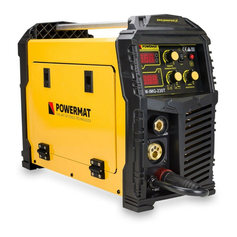
Powermat PM-IMGTS-210S User manual

PM0764
USER MANUAL
PLACE IMAGE OF MACHINE HERE
INVERTER SEMI-AUTOMATIC WELDING MACHINE
PM-IMGTS-210S
Synergy
ORIGINAL MANUAL

TABLE OF CONTENTS
TABLE OF CONTENTS ................................................ .................................................. .................................................. .................... 2
WARNING / INFORMATION SYMBOLS .............................................. .................................................. .................... 3
PURPOSE OF THE DEVICE ................................................ .................................................. .......................................... 4
SECURITY................................................. .................................................. .................................................. ......... 5
Welding safety ............................................... .................................................. .................................................. ........... 5
General safety instructions ............................................... .................................................. .................................................. ........... 7
Protection against electric shock .............................................. .................................................. .................................................. .. 8
Electromagnetic field ................................................ .................................................. .................................................. ......................... 8
Pacemakers ................................................ .................................................. .................................................. ...................................... 8
DEVICE DESCRIPTION ................................................ .................................................. .................................................. ......... 9
I Front panel ............................................... .................................................. .................................................. ........................................... 9
II. Front panel cont. + back ................................................ .................................................. .................................................. .......................... 10
MENU AND SETTINGS ............................................... .................................................. .................................................. .... 11
III Menu - selection of welding method ............................................ .................................................. .................................................. ........... 11
IV Menu - gas shield selection (MIG) ......................................... .................................................. .................................................. ............. 11
V Menu - selection of wire diameter ............................................ .................................................. .................................................. .................. 12
IV Menu - gas shield selection (MIG) ......................................... .................................................. .................................................. ............. 12
IV Menu - gas shield selection (MIG) ......................................... .................................................. .................................................. ............. 13
IV Menu - adjustment .............................................. .................................................. .................................................. ................................. 13
IV Menu - LED displays ............................................. .................................................. .................................................. ...................... 13
DESCRIPTION OF MARKINGS ON THE RATING PLATE ............................................. .................................................. ............... 14
TECHNICAL DATA................................................ .................................................. .................................................. ....... 15
GENERAL CONDITIONS OF WORK WITH THE DEVICE ............................................. .................................................. ..................... 15
General thoughts ................................................ .................................................. .................................................. ......................................... 15
Basic activities before starting work ............................................. .................................................. ...................................... 15
Activities during welding ............................................... .................................................. .................................................. ................... 16
Prohibited activities ................................................ .................................................. .................................................. ............................. 16
Basic activities after the end of work ............................................. .................................................. ............................................. 16
Final remarks ................................................ .................................................. .................................................. ...................................... 16
USING THE DEVICE ................................................ .................................................. ................................................ 17
Connecting to the network ............................................... .................................................. .................................................. ................................. 17
Loading the Electrode Wire ............................................... .................................................. .................................................. ............. 17
Connecting the shielding gas ............................................... .................................................. .................................................. ................. 18
MMA welding ............................................... .................................................. .................................................. .......................... 18
Welding with the MIG-MAG method in manual mode .......................................... .................................................. ........................................ 18
TIG-lift welding ............................................. .................................................. .................................................. .......................... 19
BASIC INFORMATION ON WELDING .............................................. .................................................. ..... 20
ELECTRODES WELDING IN PRACTICE .............................................. .................................................. .......................... 20
Electric arc welding ............................................... .................................................. .................................................. ................ 21
Choosing the right electrode ............................................... .................................................. .................................................. ................. 21
Correct welding position ............................................... .................................................. .................................................. ................ 22
Tips on arc ignition .............................................. .................................................. .................................................. ............. 22
Correct arc length ............................................... .................................................. .................................................. ......................... 23
Correct welding speed ............................................... .................................................. .................................................. .............. 23
Welding practice ................................................ .................................................. .................................................. ................................. 23
Practical exercise ................................................ .................................................. .................................................. .............................. 23
Base metals ................................................ .................................................. .................................................. .............................. 24
DEFECTS OF WELDINGS ................................................ .................................................. .................................................. ............... 25
MIG / MAG EDGE PREPARATION ............................................ .................................................. ...... 27
MIG / MAG WELDING TECHNOLOGY .............................................. .................................................. ............... 28
PRACTICAL RECOMMENDATIONS FOR MIG / MAG WELDING ............................................ ........................................... 29
METHODS OF TRANSMITTING METAL IN AN ELECTRIC ARC .............................................. ............................................. thirty
PROTECTIVE GASES ................................................ .................................................. .................................................. ........ thirty
MAINTENANCE AND STORAGE ............................................... .................................................. ............................. 31
Maintenance ................................................. .................................................. .................................................. .......................................... 31
Storage................................................. .................................................. .................................................. .................................... 32
SERVICE ................................................. .................................................. .................................................. ....................... 32
WARRANTY................................................. .................................................. .................................................. ............... 32
Manufacturer warranty exclusions ............................................... .................................................. .................................................. .......... 32
DISPOSAL OF USED DEVICES ............................................... .................................................. .................................. 33
MANUFACTURER'S DATA ................................................ .................................................. .................................................. .... 34
DECLARATION OF CONFORMITY ................................................ .................................................. .............................................. 34
2

WARNING / INFORMATION SYMBOLS
ATTENTION: Before using the device, carefully read the operating manual and safety
recommendations. Keep the instructions.
ATTENTION: A general warning sign draws the attention of each user to general dangers.
It is combined with other cautionary notes or symbols that, if ignored, could result in
personal injury or equipment damage.
ATTENTION: Disconnect the device from the mains before carrying out maintenance and
cleaning.
ATTENTION: Wear protective welding shoes.
ATTENTION: Use a welding shield or helmet.
ATTENTION: Secure the cylinder against falling over.
ATTENTION: Use welding gloves.
ATTENTION: Use a welding cloth.
SIGN OF CROSSED BASKET: Obligation to separate collection of waste equipment and a
ban on throwing it away with other waste. See the section
"DISPOSAL OF USED DEVICES DISPOSAL OF USED DEVICES"
3

PURPOSE OF THE DEVICE
The device is used for welding with any type of electrodes and welding wires. The product referred to in this manual
is an electronically controlled professional synergic semi-automatic welding machine with a "single and double pulse"
function. Designed for manual, electric welding of low-carbon and low-alloy steels, low and high-alloy steels,
aluminum and its alloys, copper and its alloys, brazing, etc. It is also intended for all kinds of welding work in
factories, industrial plants, locksmith workshops, repair shops, etc. .
The electronics of the device are based on IGBT transistors combining the advantages of two types of transistors, the ease of
control of field effect transistors and high breakdown voltage, and the switching speed of bipolar transistors.
The device has a wide range of uses, such as field work and all kinds of repair work inside buildings. It has the
function of synergic welding with single and double pulse, thanks to which it is possible to obtain the highest quality
weld when welding all weldable materials, especially those made of stainless steel and aluminum.
The device is dedicated to professionals who require meeting the highest standards for welding equipment.
Use the semi-automatic machine only for its intended purpose. Any use other than that described in this manual is
not in accordance with the intended use of the device. The user / owner, not the manufacturer, is responsible for any
damage or injuries resulting from improper use. In order to improve its products, the manufacturer reserves the right
to the possibility of differences in the above-mentioned product.
For safety reasons, the device must not be used by children and adolescents under the age of 18 and by people
under the influence of alcohol, drugs or other intoxicants.
Persons who have not read this manual should read it carefully before using the device for the first time.
4

SECURITY
This section deals with the basic safety regulations when working with a semi-automatic welding machine
B SAFETY DURING WELDING
ELECTRIC SHOCK CAN KILL: Welding equipment produces high voltage. Do not touch
the welding gun or connected welding material when the device is plugged in. All elements
forming the welding current circuit can cause electric shock, therefore it should be avoided
to touch them with bare hands and through damp or damaged protective clothing. It is not
allowed to work on wet surfaces or use damaged welding cables. ATTENTION: Removal
of external covers while the device is connected to the network, as well as using the
device with removed covers is prohibited! Welding cables, ground cable, earthing clamp
and welding equipment should be kept in a good technical condition ensuring safe
operation.
ARC RAYS CAN BURN: It is forbidden to look directly at the electric arc with the naked
eyes. Always wear a mask or helmets with an appropriate filter. Protect the bystanders
with the use of non-flammable, radiation-absorbing screens. Protect the exposed parts of
the body with suitable protective clothing made of non-flammable material.
FUMES AND GASES CAN BE DANGEROUS: The welding process produces
harmful fumes and gases that are hazardous to health. Avoid breathing these
vapors and gases. The workplace should be adequately ventilated and equipped
with a ventilation exhaust. Do not weld in closed rooms. The surfaces of the
components to be welded should be free of chemical contamination, such as
degreasing substances (solvents), which decompose during welding, producing
toxic gases.
ATTENTION: Disconnect the device from the mains before carrying out maintenance and
cleaning.
SPARKS CAN CAUSE A FIRE: Welding sparks can cause fire, explosion, and
burns to bare skin. When welding, wear welding gloves and protective clothing.
Remove or contain all flammable materials and substances from the workplace.
Do not weld closed containers or tanks containing flammable liquids. Such
containers or tanks should be rinsed before welding in order to remove flammable
liquids. Do not weld in the vicinity of flammable gases, vapors or liquids. Fire
fighting equipment (blankets
5

fire extinguishers and dry powder or snow extinguishers) should be located near the
workplace in a visible and easily accessible place.
ELECTRICAL POWER: Disconnect the mains power supply before starting any work or
repairs on the device. Check welding cables regularly. If any damage to the wire or
insulation is noticed, they should be removed immediately. Welding cables must not be
crushed, touch sharp edges or hot objects.
WELDED MATERIALS CAN BURN: Never touch welded parts with unsecured body
parts. Welding gloves and tongs should always be used when touching and moving the
workpiece.
NOISE CAN DAMAGE HEARING: Noise from some processes or devices can damage
your hearing. Hearing protection should be worn in situations of increased noise level.
FIRE OR EXPLOSION: Do not operate the device near flammable substances. Make sure
that the electrical network is properly adapted to work with the welder. Electrical overload
may cause fire.
A FALLING DEVICE CAN BE DANGEROUS: Use the transport handle to carry
the device. All devices suitable for lifting the device must have adequate lifting
capacity and a stable hitch. If the equipment is moved with a forklift truck, the forks
must be long enough to protrude beyond the equipment.
OVERLOADING MAY CAUSE OVERHEATING: Do not extend welding cycles,
allow the machine to cool down between welding cycles. If the device overheats,
shorten the welding cycle time or reduce the welding current.
STATIC DISCHARGE CAN DAMAGE THE PRINT CIRCUIT:
You must wear a grounding wrist strap before touching the printed circuit boards
and electrical system parts. Use anti-static packaging to store and transport
electrical system components.
READ INSTRUCTIONS FOR USE: Read the operating instructions carefully and
follow the information contained therein. The manufacturer is not liable for any
damage caused by non-compliance with the guidelines in this manual.
6

HIGH FREQUENCY RADIATION: Radiation
radio signals, alarm systems, computer operation, and communication equipment
may be disrupted. The user is obliged to make sure that a qualified electrician
corrects problems resulting from the disruption of the electrical system. The
electrical installation must be checked and maintained regularly. Use grounding,
shielding, and surge protection measures to minimize possible interference.
ARC WELDING CAN CAUSE INTERFERENCE: Electromagnetic energy can
interfere with the operation of electronic equipment such as computers and
computer controlled devices. Make sure that the equipment and devices around
the welding machine are electromagnetically compatible. To minimize the
possibility of interference, keep the welding cables close together and as close to
the ground as possible. In the case of electrical devices sensitive to disturbances,
the welding site should not be closer than 100m. The device must be connected
and grounded in accordance with this manual. If the interference persists, the user
must take additional measures such as changing the workplace, using shielded
cables, line filters or securing the workplace.
General safety instructions
Before you start working with this device, familiarize yourself with all the controls. Practice handling
the device and ask a professional to explain its functions, operation and techniques. Make sure that
in the event of a malfunction you can turn the device off immediately. Improper use of the device
can lead to serious injuries.
Protective devices and personal protective equipment are intended to protect your own health and the health of
third parties and to ensure that the device works properly.
• Use only spare parts and accessories supplied and recommended by the manufacturer.
Never take hold of the machine by the knives or hold it by the machine with the protective shield. Do not
carry a connected device with your finger on the on / off switch. Disconnect the plug from the mains when
you are not using the device, want to transport it or leave it unattended, and when you check or clean it.
Do not try to repair the device yourself, unless you have the appropriate training to do so. Any work not
described in this manual may only be performed by authorized service centers.
Do not carry the device by the cord. Do not use the cord to pull the plug out of the mains. Protect the cord
from high temperatures, oil and sharp edges.
Do not use the device near flammable liquids or gases. There is a risk of fire or explosion if this is not
followed.
•
•
•
•
•
7

• The user is responsible for accidents or injuries to other people and for any damage to their property.
Store the device in a dry place out of the reach of children.
Please treat your device carefully. Keep the device in such a condition that the head is clean so that it can
work better and safer. Follow the maintenance regulations.
•
•
ABOUT PROTECTION AGAINST ELECTRIC SHOCK
•
•
Make sure that the mains voltage complies with the data on the rating plate.
Before each use, check the device and the power cord with plug for damage. Avoid body contact with
earthed parts (e.g. metal fence, metal pole).
The extension cord connector must be splash-proof, made of rubber or covered with rubber. Use only
extension cords that are suitable for outdoor use and are marked accordingly.
Lay the cord away from the work area and make sure it is behind the operator.
Damaged cables, connectors, plugs and connection cables that do not comply with the regulations may not
be used. If the power cord is damaged or cut, disconnect the power plug immediately.
Do not use the device if the switch cannot be turned on or off. Damaged switches must be replaced by the
customer service center.
Do not overload the device. Only work within the specified power range. Do not use low-power machines for
heavy work. Use your device only for its intended purpose.
•
•
•
•
•
P. ELECTROMAGNETIC OIL
To reduce the build-up of an electromagnetic field in the workplace:
1. Keep the cables close together (they can be twisted or taped).
2. Organize the cables on one side of the operator as far away from him as possible.
3. Do not wrap the cables around your body.
4. Keep the power source and cables as far away from the operator as possible.
5. Connect the welding clamp as close as possible to the weld.
R HEART HEARTS
Consult a doctor before welding or staying in the place of welding. The doctor will explain possible procedures for
contact with the welding device.
8

DEVICE DESCRIPTION
IP FRONT ANEL
DESCRIPTION OF COMPONENTS
1.
2.
3.
4.
5.
6.
7.
8.
9.
Shielding gas type selection panel (MIG / MAG) Left LED display
Right LED display
Wire diameter selection panel / manual welding selection Gas flow test / wire
feed test button Multifunction button / knob
Parameter selection button (MIG-MAG / MMA) Welding method
selection panel (MIG / MMA / TIG-Lift) Selection panel (non-latched,
latched, VRD)
9

2nd P FRONT ANEL CD. + BACK
DESCRIPTION OF COMPONENTS
10.
11.
12.
13.
14.
15.
16.
Current socket (+)
Polarity reversal cable Current socket
(-)
Welding torch socket (EURO) On / off switch for the
machine
Power cord (230V)
Socket for connecting the gas pipe
10

MENUS AND SETTINGS
III M ENU - CHOICE OF WELDING METHOD
Quick selection field Description
MIG
MMA
TIG-Lift
Synergic welding with MIG-MAG wire MMA electrode welding
Welding with the TIG-Lift method
IVM ENU - GAS SHIELD SELECTION ( MIG)
Quick selection field Description
WHAT 2 MIG / MAG welding of carbon steels in a CO shield 2.
Welding of carbon steels with the MIG / MAG method in the shield of the gas mixture Ar
+ CO 2 or MIG / MAG welding in Ar shield. Welding with cored
wire (self-shielding)
MIX
FLUX
11

VM ENU - SELECTION OF THE WIRE DIAMETER
Quick selection field Description
0.6
0.8
1.0
1.2
MANUAL
Wire diameter selection in synergic mode for MIG / MAG method
MIG / MAG welding without synergy
IVM ENU - GAS SHIELD SELECTION ( MIG)
Quick selection field Description
2T
4T
VRD
Dwutakt for the MIG / MAG method. Czterotakt
for the MIG / MAG method
Initial voltage adjustment for MMA method
12

IVM ENU - GAS SHIELD SELECTION ( MIG)
Quick selection field Description
Wire feed
Gas test
Test gas flow selection button MIG / MAG. Gas flow test selection
button
IVM ENU - CONTROL
Quick selection field Description
Depending on the set welding method, you can choose: MIG / MAG - wire feed
speed
TIG Lift and MMA - welding current value
Button / knob
IVM ENU - LED DISPLAYS
Quick selection field Description
VThe current value of the welding voltage
Voltage adjustment value (range -10 to +10)
The indicator of the safety system operation of the welding machine or failure The current value of
the welding current
V +/-
Alarm
AND
13

indium
m / min
Inductance adjustment value (-10 to +10) Wire feed speed
DESCRIPTION OF MARKINGS ON THE RATING PLATE
Direct current (DC)
Symbol for single-phase alternating current (AC) with a rated frequency of 50Hz and an
operating frequency of 60Hz.
1 ~
AT 1 Rated input voltage (AC) Maximum input
current
Effective input current
No-load voltage (open circuit voltage). Output
current
The output voltage under load
Welding cycle
(This is the percentage of working time under load to the time of the full duty cycle)
•Value from 0-100%
•For the standard of this device, one full cycle of work is 10 minutes. For example, a
40% cycle allows continuous welding under load for 4 minutes. and the "rest" time
should last 6 minutes. After exceeding the working time under load, the machine is
turned off by a thermal fuse.
AND 1MAX
AND 1EFF
AT 0
AND 2
AT 2
X
The device is welded with single-phase direct current
The welder is used for MMA welding
The welder is used for MIG / MAG welding
14

TECHNICAL DATA
Model
Method
welding
Power
Recommended
security
Power consumption
Range current
welding
Tension
welding
MIG / MAG
Welding current
60% duty cycle
Welding current
100% duty cycle
Idle voltage
Wire diameter
Diameter
electrodes
Grade protection
housing
Net weight
PM-IMGTS-210S
MIG / MAG MMA
230V / 50Hz
20 [A]
6.4 kVA 5.8 kVA
20 - 210 [A] 20 - 190 [A]
15 - 24.5 [V] 20.8 - 26.4 [V]
210 A. 190 A.
160A 160 A.
55 V
0.6 / 0.8 / 0.9 / 1.0 [mm]
55 V
-
-1.6 - 5 [mm]
IP21S
11.6 kg
GENERAL CONDITIONS FOR WORKING WITH THE DEVICE
AT GENERAL WEIGHTS
a) You should start work well-rested, sober, wearing work clothes made of flame-retardant fabric or leather, cover
your hair with a beret or a cap, wear shoes with flame-retardant trousers, welding gloves and personal protection -
leather apron, welding mask , protective glasses, individual respiratory protection equipment.
b) Work related to the installation, disassembly, repair and inspection of electric welding devices should be
performed by employees with appropriate qualifications.
c) The connection of several welding energy sources should not result in exceeding, in the no-load condition, the permissible
voltage between the output circuits of the connected energy sources.
d) The welding current circuit should not be earthed, except when the items to be welded are connected to earth.
e) Welding cables connecting the workpiece with the energy source should be connected directly to the workpiece or
instrumentation, as close to the welding site as possible.
P. BASIC ACTIVITIES BEFORE STARTING WORK
The welder should:
a) read the executive documentation and the scope of welding works,
b) plan the sequence of performing individual welds,
c) prepare an appropriate binder,
d) prepare adequate face and eye protection,
15

e) check the condition of the connections of the welding installation and the working handle,
f) check that the welding operation does not pose a threat to the environment (arc radiation, possibility of ignition of
easily ignitable elements)
g) check if there is no ignition on the other side when welding on the wall,
C. WELDING EFFICIENCY
a) Secure the workplace, unless there are fixed, movable anti-glare and anti-spatter screens.
b) Use for welding electric wires and a work handle only in good technical condition (undamaged insulation).
c) Only use the correct thickness of electrodes and wires for welding.
d) Fasten and set the welded object reliably and solidly and so that it is not damaged.
e) Position the workpieces to be welded in such a way as to prevent their shifting or tipping over. Use needle hammers
and protective glasses when deflecting slag.
f) When welding inside boilers, tanks or in confined spaces, regardless of the ventilation used, use respiratory
protection.
g) When working inside tanks, boilers and other metal rooms, use 24V electric lighting.
h) Make sure that the welded element does not risk falling or moving away dangerous for the welder.
i) When welding on scaffoldings, check the condition of their efficiency.
j) Protect the respiratory tract, eyes, face and hands against burns and exposure to light by using appropriate
personal protection.
k) Turn on the individual air extraction, if there is one, so that gaseous fumes are removed from the station.
l) Use only correct, undamaged and lubricated tools and workshop aids.
C. PROHIBITED ACTIVITIES
A welder is prohibited from:
a) Gripping hot metal that is prepared for welding or after welding.
b) Repair damaged electric cables (electrical system) yourself.
c) During breaks in work, keep the electrode holder under the armpit.
d) Moving the welding mask too far from the face, putting it away before the arc goes out, and igniting the arc without
face protection.
e) Welding without proper grounding of the workpiece.
f) Use a makeshift combination of welding equipment.
g) Cause the floor at the workplace to be wet, slippery, uneven, contaminated with rubbish, obstructed.
P. BASIC ACTIVITIES AFTER THE END OF WORK
The welder should:
a) Disconnect the welding machine from voltage.
b) Check that no fire has occurred during welding at or near the stand.
c) Clean up the workplace, remove the electrode tips and welding slag.
d) Organize the welding equipment.
AT FINAL WEIGHTS
a) When welding works inside tanks, boilers or other closed rooms (up to 15m 3), the welder should be insured by
another person outside.
16

USING THE DEVICE
P. DISCONNECTING TO THE NETWORK
Before connecting this device to the mains, check the voltage, the number of phases and the
frequency.
The parameters of the supply voltage are given in the technical data section of this manual and on the rating plate of
the device.
Check the connections of the grounding conductors of the equipment to the mains.
Make sure that the mains supply can cover the input power demand of this device under normal operating conditions.
The fuse size and power cord parameters are given in the technical data of this manual.
The supply network should be characterized by a stable voltage. The cross-section of the power cables should not be less
than 2.5 mm.
Connect devices without power plugs according to the following tips.
Connection and replacement of the power cord and plug should be performed by a qualified electrician.
The wire in yellow and green insulation is the ground and should always be connected to the socket marked with the
earth symbol (PE), regardless of whether it is a 230 [V] power supply.
Earth symbol.
WITH PLACING ELECTRODE WIRE
1. Make sure that the rollers installed in the drive unit correspond to the type and diameter of the introduced
wire. If the roll groove differs with the diameter of the electrode wire, adjust the groove by turning or
replacing the roll. For steel wires, rollers with V-grooves should be used, and for aluminum wires with
U-grooves. Place the spool with the filler wire on the spool mounting mechanism, taking care that the wire
unwinding direction is in the direction of the wire entering the drive unit. Lock the spool against falling by
tightening the nut on the spool body.
The end of the wire wound on the spool, straighten or cut off the bent section, then file it off so that it is not
sharp.
To enable the introduction of the wire into the feeder, release the pressure of the feed rolls. Insert the end of
the wire into the guide at the rear of the feeder and guide it over the drive rolls and insert it into the socket
leading to the welding holder. Press the wire into the grooves of the drive rolls by tightening the clamp.
2.
3.
4.
5.
6.
7.
17

8. Remove the gas nozzle and unscrew the contact tip.
9. Switch on the device, unfold the handle so that it is in a straight line, then press the button on the handle until the
wire appears in the outlet (approx. 20 mm), release the button.
10. Screw on the contact tip, install the gas nozzle.
11. Adjust the contact force by turning the pressure knob. Too little pressure will cause the drive roller to slip.
Too much pressure force increases the feeding resistance and deforms the wire, which may result in cutting
it.
P. SHUT-OFF GAS
1. The cylinder with the appropriate shielding gas should be placed on the shelf of the semi-automatic machine and
secured against tipping over by securing it to the support using the enclosed safety devices. Remove the cap that
protects it and unscrew the cylinder valve for a moment to remove any contamination.
Install the regulator so that the gauges are vertical. Connect the semi-automatic machine with the
cylinder (outlet from the regulator) with a suitable hose.
Unscrew the reducer valve only before welding. Close the cylinder valve after welding.
Avoid welding in an open space or in a draft - a blast of air may disturb the shielding gas stream and
deprive the molten metal of its protection.
2.
3.
4.
5.
6.
S. CHOOSING THE METHOD MMA
The device can be welded with coated consumables.
1. To weld with the MMA method, select "MMA" on the selection panel. Use the panel
adjustment knob to set the welding current A.
Additionally, depending on your preferences, you can select and set Hot start and Arc force. The current
value is shown on the display of the device.
Plug the welding cables into the current sockets (6 and 8) (plus and minus).
Recommended welding current, polarity, and electrode drying requirements are given by the electrode
manufacturers on their packaging.
2.
S. CHOOSING THE METHOD MIG-MAG IN MANUAL MODE
The device can be welded with the MAG method in manual mode, i.e. with manual parameter setting - just like in a traditional
semi-automatic welding machine.
1. Select MANUAL on the control panel.
The wire diameter selection remains active, you can select one of the wire diameters, but the adjustment range for each of
them is the same. So the choice of the diameter does not really matter.
2. Select the appropriate welding control method on the control panel.
3. When welding in a gas shield, insert the polarity conversion plug into the (+) socket and the mass holder into (-).
18

4. When welding FLUX with a self-shielding wire, insert the polarity conversion plug into the socket (-
), and in (+) the mass handle.
S. CHOOSING THE METHOD TIG- LIFT
In order to weld with this method it is necessary to use an additional TIG torch equipped with a shielding gas control
valve. The TIG torch should be connected to the negative (-) polarity connector and the gas hose to the gas cylinder
regulator. Connect the positive (+) polarity connector to the material to be welded using a cable with an earth clamp.
19

BASIC INFORMATION ABOUT WELDING
Coated electrode welding (MMA) is a process in which metal is melted and then joined by heating it with an electric
arc using a fusible metal electrode coated with a flux coating. The electric current creates an electric arc between the
electrode and the material being joined. During the welding process, the electrode coating decomposes under the
influence of temperature, forming gaseous substances which are a gas shield during welding and slag.
If the electrode moves around the weld site at the correct speed, the deposited metal forms a layer called a weld.
The welder is powered by an alternating current source and can generate alternating and direct current. The best welding characteristics are
obtained when using direct current.
Voltage and current are measured in the welding circuit. The voltage (V) is regulated by the arc length between the electrode and the
welded surface and depends on the diameter of the electrode. The current is a measure of the power in the welding circuit and is
measured in amperes (A) and is adjusted via a knob.
The setting of the welding current depends on the diameter of the electrode, the size and thickness of the workpiece
and the welding position. When welding materials of the same thickness, a smaller electrode and a lower welding
current are used for materials with a small surface area than for larger surfaces. A thin metal requires less current,
and a smaller electrode requires less voltage.
It is recommended to weld when working in a horizontal and vertical position. However, when we are forced to weld in
a vertical or overhead position, it is worth setting the amperage lower than when working horizontally. The best welds
are obtained by keeping the arc short, smooth movement of the electrode and driving the electrode down at a constant
speed during melting. More detailed welding procedures are presented later in these operating instructions.
ELECTRODES WELDING IN PRACTICE
Nobody can learn to weld by reading manuals, guides, or other literature on the subject. The ability to weld correctly
can only be acquired through practice. The information contained in the attached manual is intended to help
inexperienced people understand the principles of welding with coated electrodes and facilitate the start of learning.
For more information on welding, an in-depth literature is available.
The knowledge of the welding operator must go beyond the information about the arc itself. The user of the welder
must know how to control the arc, which requires knowledge of the welding circuit and the device that supplies the
current during welding. The welding cable starts at the welding torch where the electrode is mounted and ends at the
connector where the cable is attached to the welding machine. The current flows through the welding cable to the
electrode holder and then through the electric arc. On the other side of the working arc, the current flows through the
base metal to the ground conductor, then back to the device. The system must be closed. The mass holder must be
firmly mounted on the cleaned base metal. Metal should be cleaned of paint, rust, etc. it is necessary to obtain good
current flow. Connect the ground cable as close as possible to the welding point. Avoid closing the welding circuit
through hinges, bearings, electrical systems and other such objects that may impede the flow of current in the system.
20
Table of contents
Other Powermat Welding System manuals
Popular Welding System manuals by other brands

EWM
EWM Pico 300 cel pws vrd 12V operating instructions

bester
bester MAGPOWER 2100 i Operator's manual

Pro Spot
Pro Spot i4 instruction manual

GYS
GYS TITANIUM 400 AC/DC manual

Campbell Hausfeld
Campbell Hausfeld WS0970 Operating instructions and parts manual

Clarke
Clarke King 35N operating & maintenance manual

Miller Electric
Miller Electric LMSW Series Specifications

Thermal Dynamics
Thermal Dynamics cutmaster A60 Service manual

Miller
Miller SRH 2000 CHANTIER owner's manual

Hwayuan Electric
Hwayuan Electric ZDE7-1200HD Manual instruction

ESAB
ESAB Warrior 500 operating instructions

Greencut
Greencut SOLDADOR MIG100 instruction manual