Powermat PM-IMG-220G User manual

ORIGINAL INSTRUCTIONS
USER MANUAL
inverter welder
PM-IMG-220G

1
Table of Contents
SYMBOLS WARNING / INFORMATION .............................................. ........................................... 3
APPLICATION EQUIPMENT ................................................ .................................................. ............... 3
TECHNICAL DATA ................................................ .................................................. ................................ 3
SAFETY ................................................. .................................................. ................................ 4
GENERAL THOUGHTS ................................................ .................................................. .................................... 4
Safety during welding ............................................... .................................................. 4 ....
Electromagnetic field ................................................ .................................................. .................. 6
Pacemakers ................................................ .................................................. ............................... 6
DESCRIPTION OF THE DEVICE ................................................ .................................................. ................................. 7
DESCRIPTION OF SYMBOLS ON THE LABEL ............................................. ....................................... 8
Place using the unit ............................................... .................................................. ........ 8
Current power and grounding. .................................................. .................................................. ............ 8
Welding service ................................................ .................................................. .............................. 9
Welding MMA ............................................... .................................................. ................... 11
MAG welding ............................................... .................................................. .................... 11
MIG ............................................... .................................................. ..................... 12
TIG-LIFT ............................................. .................................................. ................. 12
MIG ............................................... .................................................. ..................... 13
Table shielding gases ............................................... .................................................. ................ 14
Welding method FCAW (Flux Cored) - only for devices with alternating polarity. 15 MMA welding
.............................................. .................................................. .................... 15
BASIC INFORMATION FOR WELDING MMA ............................................. .................. 16
WELDING ELECTRODES IN PRACTICE .............................................. ................................................. 17
Electric arc welding ............................................... .................................................. ........ 18
Selection of appropriate electrode ............................................... .................................................. ........ 18
Correct welding position ............................................... .................................................. .......... 19
Tips arc ignition .............................................. .................................................. ..... 19
Proper arc length ............................................... .................................................. .................. 20
The correct welding speed ............................................... .................................................. ....... 20
Practice welding ................................................ .................................................. ........................... 20
Base metals ................................................ .................................................. ...................... 20
KEY CHARACTERISTICS FOR WELDING TIG ............................................. ....................... 21
WELDING PARAMETERS DRAW ............................................... ........................................... 22
INSRUKCJA INSTALLATION AND USE .............................................. ................................................. 22
MAINTENANCE AND SERVICE ............................................... .................................................. ...................... 22

2
Maintenance ................................................. .................................................. ................................... 22
Malfunctions welding ............................................... .................................................. ............... 23
Service ................................................. .................................................. ............................................. 24
REMOVAL OF USED ............................................... .................................................. ....... 24
COMPANY INFORMATION ................................................ .................................................. ............................ 24
DECLARATION OF CONFORMITY ................................................ .................................................. .................... 25

3
SYMBOLS WARNING / INFORMATION
APPLICATION EQUIPMENT
Inverter welder is used for MIG / MAG, MMA (any type of welding electrodes) and TIG Lift. The product to which this
manual is electronically controlled MIG / MAG / MMA / TIG Lift. Electronics devices based on the IGBTs combine the
advantages of two types of transistors FET ease of operation and high breakdown voltage and switching speed of
bipolar transistors. Use only approved gas cylinders.
The device is versatile, such as performing field work and all kinds of repair work inside buildings.
Use the equipment only for its intended purpose. Any other use than described in this manual is the improper use of
the device. For resulting from improper use damage or injuries responsibility of the user / operator and not the
manufacturer. Producer in order to improve its products reserves the right to possibility of differences in the above
mentioned product.
TECHNICAL DATA
Model: PM-IMG-220T
Welding method MIG / MAG MMA
Power 230V / 50Hz
Power consumption 6,1kVA 5,8kVa
Welding current range 40-220A 20-170A
Range of welding voltage 16-25V -
Welding current duty cycle of 100% 170A 132A
Welding current 60% duty cycle 220A 170A
wire feeder Internal -
The diameter of the wire / electrode 0.6 / 0.8 / 1.0 mm 2.5 - 4 mm
insulation class F
Level of security IP21S
Weight 12 kg
WARNING: Before using the device please read the instruction manual and safety instructions. WARNING: Before using the device please read the instruction manual and safety instructions.
Keep these instructions.
WARNING: Keep a safe distance from bystanders during operation.WARNING: Keep a safe distance from bystanders during operation.
WARNING: To protect the unit from rain and moisture. WARNING: To protect the unit from rain and moisture.

4
SECURITY
Before starting work carefully to become familiar with the manual. Keep them for future reference. For damages
resulting from failure to observe these instructions, the manufacturer is not liable.
The greatest danger is prohibited to perform the following steps:
and) Welders use for purposes other than those described in the manual. and) Welders use for purposes other than those described in the manual.
b) Using a welder by people niezapoznane manual. b) Using a welder by people niezapoznane manual.
c) Using welders without proper, protective clothing and footwear that supports c) Using welders without proper, protective clothing and footwear that supports
protecting the foot.
d) The use of the device by a person under the influence of alcohol, drugs or other substances d) The use of the device by a person under the influence of alcohol, drugs or other substances
drugs. And also by persons with reduced physical, sensory or mental capabilities, or lacking experience or
knowledge concerning the use of this type of equipment.
GENERAL THOUGHTS
Safety during welding
ELECTRIC SHOCK CAN KILL: Welding apparatus produce a high voltage. Do not touch the torch, ELECTRIC SHOCK CAN KILL: Welding apparatus produce a high voltage. Do not touch the torch,
welding material connected when the device is turned on to the network. All the elements forming
the welding current circuit can cause electrical shock and should therefore be avoided
touching them with bare hands and by wet or damaged protective clothing. Never work on a wet surface, or use
damaged welding cables. NOTE: Removing the external time when the device is connected to the network, as well as
the use of the device with the covers removed is prohibited! Welding cables, ground cable, earthing terminal and
welding equipment should be kept in good condition, ensuring safety.
ARC RAYS CAN BURN: It is not allowed to look directly at the eyes uncovered and exposed to an ARC RAYS CAN BURN: It is not allowed to look directly at the eyes uncovered and exposed to an
electric arc. Always wear a mask or helmets protected with a suitable filter. Bystanders, nearby,
protected with non-combustible, absorbing radiation screens. Protect
exposed parts of the body suitable protective clothing made of non-combustible material.
FUMES AND GASES CAN BE DANGEROUS: In the welding process are produced noxious fumes FUMES AND GASES CAN BE DANGEROUS: In the welding process are produced noxious fumes
and gases hazardous to health. Avoid breathing these fumes and gases. Workplace should be
adequately ventilated and equipped with exhaust ventilation. Do not weld in confined spaces.
surfaces
the elements to be welded should be free from chemical impurities such as degreasing agents (solvents) which
decompose during welding to produce toxic gases.
ELECTROMAGNETIC FIELDS MAY BE DANGEROUS: Electric current flowing through wires ELECTROMAGNETIC FIELDS MAY BE DANGEROUS: Electric current flowing through wires
Welding produces electromagnetic field around it. Field

5
Electromagnetic may interfere with pacemakers. Welding cables should be arranged in parallel, as close as possible
to each other.
SPARKS CAN CAUSE FIRE: Sparks generated during welding can cause fire, explosion and burns SPARKS CAN CAUSE FIRE: Sparks generated during welding can cause fire, explosion and burns
unprotected skin. When welding should be wearing welding gloves and protective clothing. Remove
or secure any flammable materials and substances from the workplace. Do not weld
closed containers or receptacles in which there were flammable liquids. Such containers or tanks should be rinsed
prior to welding in order to remove flammable liquid. Do not weld near flammable gases, vapors or liquids. Fire
extinguishing equipment (fire blankets and fire extinguishers powder or snow) should be located close to the
workstation in a conspicuous and easily accessible place.
POWER SUPPLY: Disconnect the power supply before carrying out any work, repairs on the device. POWER SUPPLY: Disconnect the power supply before carrying out any work, repairs on the device.
Regularly check the welding cables. If you note any damage to the wire or insulation should be
removed immediately. Welding wires can not be overwhelmed,
touch sharp edges or hot objects.
WELDED MATERIALS CAN BURN: Never touch the parts to be welded unprotected parts of the WELDED MATERIALS CAN BURN: Never touch the parts to be welded unprotected parts of the
body. While touching and moving the welding material, always use gloves and welding pliers.
Noise can damage hearing: Noise-induced, some processes Noise can damage hearing: Noise-induced, some processes or
devices can damage hearing. Wear hearing protection in situations of increased noise levels.
FIRE OR EXPLOSION: Do not use the machine near flammable substances. Make sure that the FIRE OR EXPLOSION: Do not use the machine near flammable substances. Make sure that the
electrical network is properly configured to work with the welder. Overloading the power supply may
cause fire.
FALLING EQUIPMENT CAN BE DANGEROUS: To move the machine, use the handle of transport. FALLING EQUIPMENT CAN BE DANGEROUS: To move the machine, use the handle of transport.
All the equipment necessary to lift the unit must have sufficient capacity and stable hook. When
moving the machine by forklift truck, the forks must be long enough to protrude beyond the device.
Overload can cause overheating: Do not extend the cycle of welding, welding between cycles allow Overload can cause overheating: Do not extend the cycle of welding, welding between cycles allow
the device to cool. In the case of excessive heating of the device, shorten the cycle time of welding or
reduce the welding current.

6
STATIC DISCHARGE MAY DAMAGE THE PRINTED CIRCUIT: Before touching the printed circuit STATIC DISCHARGE MAY DAMAGE THE PRINTED CIRCUIT: Before touching the printed circuit
boards and parts of the electrical system should be assumed grounding wrist-strap. Use of antistatic
packaging is storing and transporting electrical components.
READ INSTRUCTIONS: Carefully read the manual and follow the information contained therein. For READ INSTRUCTIONS: Carefully read the manual and follow the information contained therein. For
any damage caused by failure to comply with the guidelines of this manual manufacturer is not
liable.
HIGH RADIATION FREQUENCY: high radiation
frequency radio signal can zakłucać, alarm systems, work computers and communications
equipment. User is obliged to ensure a qualified electrician correct the problems resulting from
zakłucenia electrical installation. Regularly check and maintain electrical installations. Use
grounding, shielding and anti-surge protection measures to minimize any zakłucenia.
ARC WELDING CAN CAUSE ZAKŁUCENIA: Electromagnetic energy can interfere with electronic ARC WELDING CAN CAUSE ZAKŁUCENIA: Electromagnetic energy can interfere with electronic
equipment such as computers and computer-controlled equipment. Make sure that the hardware
devices in the work environment welders are electromagnetically compatible. To minimize the
potential for interference stick welding wires close to each other, as close to the ground. IN
If electrical noise sensitive spot welding should not be closer than 100m. The device must be connected and
grounded in accordance with this instruction. If noise still persists the user needs to take additional measures such as
changing jobs, the use of shielded cables, filters, linear and securing jobs.
CYLINDER MAY EXPLODE: Use only approved cylinders properly operated regulator. Transported CYLINDER MAY EXPLODE: Use only approved cylinders properly operated regulator. Transported
and stored in an upright position only. Protect from heat sources, tipping and mechanical damage.
Keep in good condition all the elements of the gas.
Electromagnetic field
To reduce the amount of electromagnetic fields in the workplace include:
1. Keep cables close together (you can turn the tape or taped). 1. Keep cables close together (you can turn the tape or taped).
2. Organize the wires from one side of the operator as far as possible from him. 2. Organize the wires from one side of the operator as far as possible from him.
3. Do not wrap the cables around the body. 3. Do not wrap the cables around the body.
4. The power source and wires should be as far away from the operator as possible. 4. The power source and wires should be as far away from the operator as possible.
5. Connect the terminal welding seam as close as possible. 5. Connect the terminal welding seam as close as possible.
pacemakers
You should consult your doctor before welding and welding being in place. The doctor will explain the procedure if
any of the contact with the welding apparatus.

7
DESCRIPTION OF THE DEVICE
PM-MIG-220T
1. Ammeter 8. Wire feed speed knob (MIG)
2. LED overload 9. Voltmeter (MIG) 9. Voltmeter (MIG)
3. The switch MIG / MMA / TIG-LIFT 10. Socket polarity (+) 10. Socket polarity (+)
4. LED planting 11. Socket polarity (-) 11. Socket polarity (-)
5. The welding current control (MMA) 12. The socket welding torch for MIG / MAG
6. The wire feed speed 13. Connector cable polarity 13. Connector cable polarity
7. Knob voltage welding (MIG)

8
ABOUT MARKING THE PIS LABEL ABOUT MARKING THE PIS LABEL ABOUT MARKING THE PIS LABEL
Current (DC)
Symbol single phase alternating current (AC) of the rated frequency 50Hz
and 60Hz operating frequency.
AT 1 Nominal input voltage (AC)AT 1 Nominal input voltage (AC)AT 1 Nominal input voltage (AC)
AND 1max Maximum input currentAND 1max Maximum input currentAND 1max Maximum input current
AND 1EFF Effective input currentAND 1EFF Effective input currentAND 1EFF Effective input current
AT 0 No-load voltage (load voltage) AT 0 No-load voltage (load voltage) AT 0 No-load voltage (load voltage)
AND 2 output current AND 2 output current AND 2 output current
AT 2 The output voltage under load AT 2 The output voltage under load AT 2 The output voltage under load
X
welding cycle
(This percentage ratio of working time under load to full duty cycle)
•The value of 0-100%
• Standard for this device, one full cycle is 10 min. For example, 40% of the
cycle allows for continuous welding under load for 4 minutes. and the time
to "rest" should last 6 minutes. When the time under load the machine is
switched off by the thermal fuse.
The device welded single-phase DC
Welder is used for MIG / MAG welding
IP21S Symbol of protection class.
Place of use of the device
The device can be used only in well-ventilated place.
Before working at the site of use should always take into account the guidelines for safety contained in the "SAFETY"
and "GENERAL". Welding cables must be connected to the output of the welding power source to the welding
machine. Welder power cord must be connected to a 230V AC power source.
Current power and grounding.
Only qualified personnel may perform installation and modification of the electricity grid.

9
Warning! It is forbidden to use the device or completely dismantled the housing removed, it may cause electric shock Warning! It is forbidden to use the device or completely dismantled the housing removed, it may cause electric shock
and lead to severe injury. Do not touch the energized equipment.
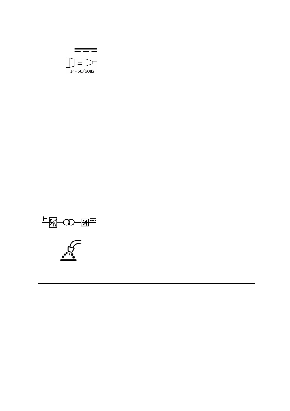
Before installing the unit, check electrical network to which the device is connected meets the requirements placed on
the nameplate and that it meets all local and national standards. Keep in mind that different models of welding
machines may have different requirements for the electricity grid.
1. Before connecting check whether the network meets the requirements of the welding machine. 1. Before connecting check whether the network meets the requirements of the welding machine.
2. Connect the PE or green / yellow ground wire to the grounding system in accordance with the 2. Connect the PE or green / yellow ground wire to the grounding system in accordance with the
national regulations.
3. Connect the welding cables to the device, then the power cord to a single-phase network 3. Connect the welding cables to the device, then the power cord to a single-phase network
the electric voltage of 230V and frequency of 50Hz.
welding service
1. The display shows the welding current (when the arc is struck shows the actual value). 1. The display shows the welding current (when the arc is struck shows the actual value).
2. LED overheating ( OC) lights up in case of overheating. In this case2. LED overheating ( OC) lights up in case of overheating. In this case2. LED overheating ( OC) lights up in case of overheating. In this case2. LED overheating ( OC) lights up in case of overheating. In this case
Wait to cool down the unit before continuing work.
3. Mode switch MIG / MMA / TIG-LIFT. 3. Mode switch MIG / MMA / TIG-LIFT.
4. Power LED shows the power. 4. Power LED shows the power.
5. Welding current regulator mode MMA (electrode). 5. Welding current regulator mode MMA (electrode).
6. Press and hold the button to temporarily increase the speed of delivery 6. Press and hold the button to temporarily increase the speed of delivery
wire to the maximum value. When you press the welding wire feeder gives a maximum speed
7. Voltage regulation of welding current mode IMG (wire) is done using the knob 7. Voltage regulation of welding current mode IMG (wire) is done using the knob
front panel. It is usually sufficient that the value on the dial is equal to the adjustment knob is set to the
wire feed speed. Higher voltage arc is longer, which results in less depth of penetration and wider weld
bead. Too much tension increases spatter, porosity, and the risk of flooding przyklejeń. Too little tension
may cause process instability.
8. Feed speed of the welding wire is carried out by rotating 8. Feed speed of the welding wire is carried out by rotating
knob. At a given value of the arc voltage must be adjusted so that the wire feed speed the fusion was stable
waveform.
9. Displays current welding (MIG) 9. Displays current welding (MIG)
10. Connector positive polarity (+) to the polarity applied to the socket must be connected 10. Connector positive polarity (+) to the polarity applied to the socket must be connected
polarizing the wire connector (see 13).
11. Connector negative polarity (-) to apply the polarity must be connected to the socket 11. Connector negative polarity (-) to apply the polarity must be connected to the socket
polarizing the wire connector (see 13).
12. MIG welding gun connector (must be connected when MIG welding 12. MIG welding gun connector (must be connected when MIG welding
13. WARNING polarized connector 13. WARNING polarized connector 13. WARNING polarized connector
and. in the case of gas welding (MIG) connect the polarizing slot and. in the case of gas welding (MIG) connect the polarizing slot
pole (+) while the chuck mass for the (-).
b. In the case of the welding wire itself casing (MIG) connect the polarized b. In the case of the welding wire itself casing (MIG) connect the polarized
to the socket pole (-) mass while the chuck to the (+)

10
Fig. 1 of the connection device deterministic (for welding shield Connect a gas cylinder in accordance with the drawing of gas into
the socket so the device)
Attaching the welding wire
1. Before the spool of wire, make sure that the roller drive unit 1. Before the spool of wire, make sure that the roller drive unit
They correspond to the type and diameter of the welding wire fed. Rollers with a groove of V-shaped
correspond drutom steel, while the U-shaped drutom aluminum.
2. Apply a spool of wire on a spool holder, remembering that the direction of development 2. Apply a spool of wire on a spool holder, remembering that the direction of development
reel was in line with the direction of wire feed.
3. Tighten the nut on the body of the reel. 3. Tighten the nut on the body of the reel.
4. Unroll the end of the wire located on the reel, you need to file off the end, so that was not sharp 4. Unroll the end of the wire located on the reel, you need to file off the end, so that was not sharp
and does not damage the internal parts of the machine.
5. Release the pressure feed rollers 5. Release the pressure feed rollers
6. The end of the guide wire inserted in the back of the tray and carry it over the roll 6. The end of the guide wire inserted in the back of the tray and carry it over the roll
and a drive slide to a port leading to the welding torch.
7. Push wire in the groove of the drive roller by tightening a guiding function. 7. Push wire in the groove of the drive roller by tightening a guiding function.
8. Remove gas nozzle and contact tip, unscrew. 8. Remove gas nozzle and contact tip, unscrew.
9. Turn on, then set the wire feed knob to position 9. Turn on, then set the wire feed knob to position
central.
10. Open welding line, then press the button on the handle until 10. Open welding line, then press the button on the handle until
the emergence of a wire in the outlet at about 20mm, then release the button.
11. Screw the contact tip, replace the gas nozzle. 11. Screw the contact tip, replace the gas nozzle.
12. Turn the knob to adjust the downforce roll, turning clockwise increases the downforce 12. Turn the knob to adjust the downforce roll, turning clockwise increases the downforce
left turn reduces the strength of pressure. Too small a clamping force causes sliding of the drive roller.
Excessive force causing increase in the resistance of a wire, which can cause deformation and
machining.

11
Connection of protective gas
1. The bottle of carefully selected protective gas must be set on the shelf and semi-automatic 1. The bottle of carefully selected protective gas must be set on the shelf and semi-automatic
secured by a chain.
2. Remove the protective cap and unscrew the cylinder valve briefly to remove 2. Remove the protective cap and unscrew the cylinder valve briefly to remove
possible contaminants.
3. Install the regulator so that the gauge was in a vertical position. 3. Install the regulator so that the gauge was in a vertical position.
4. Connect the welder with cylinder using a hose. 4. Connect the welder with cylinder using a hose.
5. Reducer valve should loosen just before welding. After5. Reducer valve should loosen just before welding. After
welding immediately turn off the valve.
Welding MMA MMA- welding technique that uses the same backing electrode. Welding MMA MMA- welding technique that uses the same backing electrode.
1. Make sure that the welding machine is disconnected from the power source. 1. Make sure that the welding machine is disconnected from the power source.
2. Electrode holder hook up to the (+). 2. Electrode holder hook up to the (+).
3. Mass grip hook up to the (-) terminal. 3. Mass grip hook up to the (-) terminal.
4. Turn on the power. 4. Turn on the power.
5. Set the welding mode position MMA. 5. Set the welding mode position MMA.
6. Set the parameters for the welding work. 6. Set the parameters for the welding work.
7. Start the welding process. 7. Start the welding process.
Material thickness SIZE ELECTRODE WELDING CURRENT (A)
<1 mm / .040 " 1.5mm / 1/16 " 20-40
2 mm / .080 " 2mm / 3/32 " 40-90
3 mm / 8.1 " 3.2mm / 1/8 " 90-110
4-5 mm / 3/16 " 3.2-4mm / 1/8 "-3/16" 90-130
6-12 mm / 1/4 "-1/2" 4-5mm / 3/16 " 130-200
MAG welding MAG - welding method, which uses chemically active shielding gas, eg. CO 2.MAG welding MAG - welding method, which uses chemically active shielding gas, eg. CO 2.MAG welding MAG - welding method, which uses chemically active shielding gas, eg. CO 2.
8. Make sure that the welding machine is disconnected from the power source. 8. Make sure that the welding machine is disconnected from the power source.
9. Connect the shielding gas cylinder. 9. Connect the shielding gas cylinder.
10. Conductor terminal of mass put on welded material. 10. Conductor terminal of mass put on welded material.
11. Handle massive place in the socket (-) welding. 11. Handle massive place in the socket (-) welding.
12. Plug welding torch in the slot to give the EURO. 12. Plug welding torch in the slot to give the EURO.
13. Polarized connector insert in the socket welding (+). 13. Polarized connector insert in the socket welding (+).
14. Turn on the power. 14. Turn on the power.
15. Set the mode switch position MIG welding. 15. Set the mode switch position MIG welding.
16. A suitable set operating parameters for welding. 16. A suitable set operating parameters for welding.
17. Start the welding process. 17. Start the welding process.

12
MIG MIG - welding process, wherein the shielding gas used is chemical inert gas, for example. Argon, helium. MIG MIG - welding process, wherein the shielding gas used is chemical inert gas, for example. Argon, helium.
1. Make sure that the welder is odłączna power. 1. Make sure that the welder is odłączna power.
2. Replace the torch to one in which the resilient conduit is formed of a Teflon 2. Replace the torch to one in which the resilient conduit is formed of a Teflon
3. Connect the shielding gas cylinder. 3. Connect the shielding gas cylinder.
4. Place the ground cable terminal on the welded material. 4. Place the ground cable terminal on the welded material.
5. Handle massive place in the welding socket (-). 5. Handle massive place in the welding socket (-).
6. Plug welding torch in the slot to give the EURO. 6. Plug welding torch in the slot to give the EURO.
7. Polarized connector insert in the socket welding (+). 7. Polarized connector insert in the socket welding (+).
8. Turn on the power. 8. Turn on the power.
9. Set the switch to the IMG. 9. Set the switch to the IMG.
10. A suitable set operating parameters for welding. 10. A suitable set operating parameters for welding.
11. Start the welding process. 11. Start the welding process.
WARNING! Before welding aluminum wire should be changed wire feed roller (groove in the shape of a "U"
WARNING. Do not change the settings of the welding current during welding.
TIG-LIFT
TIG-LIFT - welding process is tungsten inert gas which is used for welding metal alloy (not suitable for aluminum) TIG-LIFT - welding process is tungsten inert gas which is used for welding metal alloy (not suitable for aluminum)
1. Make sure that the welder is odłączna power. 1. Make sure that the welder is odłączna power.
2. Attach the TIG torch to control the flow of gas into the socket 2. Attach the TIG torch to control the flow of gas into the socket
polarizing negative (-).
3. Mass handle into the socket of the positive polarity (+). 3. Mass handle into the socket of the positive polarity (+).
4. Turn on the power. 4. Turn on the power.
5. Turn the switch TIG-LIFT. 5. Turn the switch TIG-LIFT.
6. Set the welding parameters. 6. Set the welding parameters.
7. Start the welding process. 7. Start the welding process.
Remember to stick with the filler material placed directly in the nucleolus. The welding process is TIG welding method
in which the arc is maintained by the tungsten electrode (usually tungsten). Welding area (electrode, arc and weld
pool) is protected against contamination by an inert gas (eg. Argon), which constantly flows through the welding torch.

13
MIG
During welding, the torch moves the welding wire, which is constantly melting in an electric arc. The fluid material of
the welding wire connected to a combination of material to form a liquid weld pool. When moving the welding torch,
lake follow, to solidify at the edges and creating a durable combination of materials. Shielding gas is supplied through
the gas nozzle located on the torch. Gas protects the molten metal from the atmosphere, pollution and cooled welding
torch.
Fig. 2
Scheme MIG / MAG
Fig. 2
Scheme MIG / MAG
Material should be completely cleaned of contaminants such as rust or paint. Any dirt have an impact on changing the
direction of welding and weld weakness. The area under the ground terminal must also be properly cleaned. To clean
is best to use an angle grinder with a sanding disc or a brush, or a steel brush.
The best results are obtained by holding the torch with both hands (you should then use a welding helmet), it affects
the use to control the position of the burner. Be aware of the welding position to have a good view on the weld and do
not breathe too gases produced during welding.
After the burner tip deviation from the vertical is achieved better visibility of the welding process. Contact tip should be
approximately 6 to 10 mm over a weld material. A good idea of how high the torch to keep the material will allow us to
trim the wire in the burner length 10mm
Among the many possible methods of carrying the torch frequently used zig-zag movements pushed, which are
aimed at keeping the bow in the direction of welded components. Method Front, which is pushing the burner is better
than the method from the rear (pulling burner) due to increased shielding gas coverage, and introduces joint on each
edge of the materials to be joined, resulting in a flat and neat seam. Exceptions are thin materials during welding,
which are two possible methods. Shall also conduct a simple burner without zigzag treats in this method required a lot
of experience. The easiest way to practice the arrangement of the weld in a single element. After a few seconds, weld
should decompose. If the puddle becomes too large welding is too slow or too high setting welding voltage; maybe
this

14
lead to burnout material welded. If the weld does not break down this welding dispenses too quickly and the seam is not
melted through the material.
Increasing the voltage increases the weld penetration (penetration depth) and elongation of the arc.
It is possible to weld with poor fitting the amperage, penetration may be too large or too small, but the welds remain
valid. By contrast, the mismatched wire feed speed, welding can not be obtained. The method for selecting a wire
feed speed experimentation. Wire feed speed adjustment is possible during welding, so the welding must be set in
the vicinity. Set the value of the current and the welding time to adjust the wire feed speed to achieve an optimal
effect.
Warning! Chamfering (grinding the edge of the materials to be welded in a V-shape) significantly reduces the
power required for welding of the material thickness. Grafting
The heat acting on the welded material interferes with its structure. When welding two pieces fitted together perfectly
after a few centimeters welds the gap between them starts to increase and further aesthetic weld location will be
impossible. The solution becomes spot welding. Between points vaccination in places unconnected continuous welds
should be placed. This will allow for good penetration, thereby solid connection.
Table gases osłono Outgoing Table gases osłono Outgoing
shielding gas chemical
action
welded metals
Argon Inert Basically, all metals except for carbon steels
Helium Inert Al, Cu, Cu alloys, Mg alloys, ensured high energy linear
welding
20-80% Ar + He Inert Al, Cu alloys, Cu, Mg, provides a large heat input welding,
low thermal conductivity gas
25-20% Ar + N 225-20% Ar + N 2 reducing Copper welding with high heat input arc glow better than the
arc shield 100% N 2arc shield 100% N 2
Ar + 12% O 2Ar + 12% O 2 weakly oxidising Recommended mainly for welding stainless steels and alloy
steels
Ar + 3-5% O 2 Ar + 3-5% O 2 oxidising Recommended for welding of carbon steels and
low-alloy steel
WHAT 2WHAT 2 oxidising recommended only down welding steel
low carbon
Ar + 20 - 50% CO2 oxidising Recommended only for welding carbon steel and low-alloy
steel
Ar + 10% CO 2 + 5% O2 Ar + 10% CO 2 + 5% O2 Ar + 10% CO 2 + 5% O2 Ar + 10% CO 2 + 5% O2 oxidising Recommended only for welding carbon steel and low-alloy
steel
CO2 + 20% O2 oxidising recommended only down welding steel
low-carbon and low-alloy

15
90% He + 7.5% Ar + 2.5% CO 290% He + 7.5% Ar + 2.5% CO 2 weakly oxidising Corrosion resistant, short-arc welding
60% He + 35% Ar + 5% CO 260% He + 35% Ar + 5% CO 2 oxidising Low alloyed steels, high-impact, short-arc welding
Welding method FCAW (Flux Cored) - only for devices with alternating polarity.
Warning! When welding wire shielding itself must change the polarity of the device.
1. Make sure that the welding machine is disconnected from the power source. 1. Make sure that the welding machine is disconnected from the power source.
2. Put the spool of wire shielding itself. 2. Put the spool of wire shielding itself.
3. Conductor terminal of mass put on welded material. 3. Conductor terminal of mass put on welded material.
4. Welding cable plug socket in place the EURO. 4. Welding cable plug socket in place the EURO.
5. Replace wiring polarity. 5. Replace wiring polarity.
6. Turn on the seeding machine. 6. Turn on the seeding machine.
7. Switch welding method set the position of the IMG 7. Switch welding method set the position of the IMG
8. Set the parameters for the welding work. 8. Set the parameters for the welding work.
9. Start welding. 9. Start welding.
Description of the method
FCAW - a method similar to MIG / MAG welding with the difference that instead of solid wire cored wire is used. The
wire is filled with welding powder producing protective gases is not, so the need to provide the shielding gas from the
cylinder.
A welding wire guard itself is the same as the MIG / MAG difference is the use of a wire which has a core is filled with
powder. Under heat generated during the welding of the core is molten and powder produced a gas atmosphere
surrounding the liquid pond. In the application of the wire itself casing can be dispensed with the gas supply from a
cylinder, which greatly influences the welding process.
Warning! When welding wire shielding itself must change the polarity of the device. Welding
MMA
1. Connect to the power welder, dial located at the rear of the unit. 1. Connect to the power welder, dial located at the rear of the unit.
2. Connect the ground wire to the quick and the workpiece. 2. Connect the ground wire to the quick and the workpiece.
3. Mount the electrode in the torch, and then connect the wire from the quick coupling. 3. Mount the electrode in the torch, and then connect the wire from the quick coupling.
4. Switch to the ON position and make sure the power LED indicator lights up. 4. Switch to the ON position and make sure the power LED indicator lights up.
5. You can start the process of welding. 5. You can start the process of welding.
6. After welding is complete, move the electrode from the work piece and set 6. After welding is complete, move the electrode from the work piece and set
OFF switch in the OFF position.
WARNING! The arc starts at the moment when the welding electrode to the welding point touch and then
will be moved to a distance the length of the arc.

16
Figure 3
Figure 3. One specific example of welding by means of electrodes. Figure 3. One specific example of welding by means of electrodes.
Warning! At the time of exceeding the cycle provided for the amperage thermal circuit breaker lock the device Warning! At the time of exceeding the cycle provided for the amperage thermal circuit breaker lock the device
(indicated by yellow LED Overload) until cool welding.
If your machine or its accessories will begin to work properly you should refrain from further work and contact a
qualified service center.
BASIC INFORMATION FOR MMA WELDING
Otulinowymi welding electrodes (MMA) is a process in which metal is melted, and then combined, by heating it by
means of electric arc with consumable electrode coated metal wrapper flux. The electric current generates an electric
arc between the electrode and the material combined. During the welding electrode coating decomposes under heat
to form the gaseous substances which shield gas during the welding and slag.
If the electrode moves along a weld spot at the right speed deposited metal forms a layer called the seam.
Welding is powered by an AC source and can generate alternating current and constant. The best characteristics of the weld
obtained using a constant current.
In the circuit welding measured voltage and current. Voltage (V) is controlled by the arc length between the electrode
and welded surface and depends on the diameter of the electrode. It is a measure of the current in the welding circuit,
and is measured in amperes (A), is controlled by the dial. Setting the welding current is dependent on the diameter of
the electrode size and thickness of the welded material and the welding position. When welding materials with the
same thickness, materials with a small area is used lower electrode and a lower welding current than for larger
surfaces. Thin metal requires less power, and smaller electrode requires less power.

17
It is recommended that during welding work in the horizontal and vertical positions. However, while we are forced to
weld in vertical or overhead should set the current lower than the level during operation. The best welds are obtained
while maintaining a short arc, smooth movement of the electrode and the electrode leading down at a constant speed
during melting. More detailed welding procedures are presented in the following pages Supported.
WELDING ELECTRODES IN PRACTICE
No one can learn to weld by reading the instruction manual or other literature on the subject. The ability to correct
welding can be purchased only through practice. The information contained in the attached manual to help you
understand those rules inexperienced welding with coated electrodes and make it easier to start learning. For more
information about welding can reach for a comprehensive literature deeply about.
Knowledge welding operator must go beyond information about the arc. User welders must know how to control the
arc, which requires knowledge of the circuit and the welding device that provides current during welding. The welding
cable starts in the torch, wherein the electrode is mounted, and the end on the connector, wherein the cable is
attached to the welding machine. Current flows through the wire to the welding electrode holder and then by the
electric arc. On the other side of the working arc current flows through the wire to the base metal mass, then back to
the device. The system must be closed. Mass holder to be stably mounted on the metal base cleared. Metal must be
cleaned of paint, rust, etc. It is necessary to obtain a good current flow. Connect the ground cable as close as
possible to the welding point. Avoid closing the circuit through the welding hinges, bearings, electrical systems and
other such items that may impede the flow of current in the system. The electric arc is formed in a space between the
work piece and the welding electrode tip mounted on the torch. The molten metal moves along the arc for the
combination of materials, forming a weld bond.
Electrode Welding requires a strong grip and a welding tip, stable hands, good vision and good mental health. The
operator controls the welding arc welding and thus, the quality of the weld created.

18
Electric arc welding
Fig. 4
Figure 4. Presents phenomena occurring during arc welding, which is greatly enlarged what is seen by the welder. Figure 4. Presents phenomena occurring during arc welding, which is greatly enlarged what is seen by the welder.
Curved space is shown in a central position in the picture. Arc formed at a location between the electrode tip and the
base material. The arc welding reaches 3315 about C, which is sufficient to melt the base metal. Since the arc is very base material. The arc welding reaches 3315 about C, which is sufficient to melt the base metal. Since the arc is very base material. The arc welding reaches 3315 about C, which is sufficient to melt the base metal. Since the arc is very
bright you can not look at him bare eyes, it can cause very painful burns of the retina or permanent eye damage.
They are designed for welding specialist welding masks and helmets protect the eyes during welding.
When working with an electric arc welder begins to "pull" handle, which is comparable to a stream of water from a
garden hose for use at the ground. The molten metal forms a lake or crater (small area of the molten metal surface) garden hose for use at the ground. The molten metal forms a lake or crater (small area of the molten metal surface)
which follow for the electric arc. During the movement of the electrode puddle is cooled and solidifies. Slag emitted
during welding protects the weld during welding.
Selection of a respective electrode
The function of the covered electrodes is not only the transfer of power to the electric arc. The electrode is
constructed of a metal core and a cover. The metal core is melted in an electric arc to fill the gap between the two
pieces of combined metal. Lagging also melts or burns in an electric arc playing the same important functions in the
welding process. During the melting of the electrode decompose chemical compounds contained in the electrode
coating to form gaseous products, which stabilizes the electric arc cloud protects the molten metal from oxidation and
pollution in the atmosphere. Other chemicals get together with the molten metal from the core of the electrode to the
weld pool to form a slag that forms on the weld layer protecting from further oxidation during cooling.
The differences for the different types of electrodes refer mainly to the type of the buffer zone. Changing the outer
coating significantly affects the characteristics of welding. by understanding

19
differences in the types of buffer zones to gain knowledge select the right electrode for the job.
When choosing the electrodes need to consider:
1. Implementation example. Steel, mild steel and stainless steel. 1. Implementation example. Steel, mild steel and stainless steel.
2. The thickness of the welded material. 2. The thickness of the welded material.
3. Position in which the weld is made. 3. Position in which the weld is made.
4. Technical state of the base metal. 4. Technical state of the base metal.
5. Own skills on using a welder. 5. Own skills on using a welder.
The first four points are necessary for the proper use of the welder without mastering their work will be hard and
tedious.
Correct welding position
The welding position presented is described for right-handed, in the case of left-handers will look exactly the opposite.
1. Catch the welding gun with his right hand. 1. Catch the welding gun with his right hand.
2. Put your left hand under your right hand. 2. Put your left hand under your right hand.
3. Put your left elbow to the left side of the body. If3. Put your left elbow to the left side of the body. If
you can weld with both hands. This will better control electrode.
Try to weld from left to right (if you're right-handed). You will see more precisely the welding area.
Fig. 5
Figure 5. Keep the electrode at a slight angle as shown in the figure. Figure 5. Keep the electrode at a slight angle as shown in the figure.
Tips arc ignition
Make out that handle mass has good contact with the weld workspace.
Lower welding helmet and rub against metal electrode welding in place until you see sparks. While rubbing lift the
electrode at about 3mm to stabilize the arc.
Warning! If you stop electrode while rubbing stick electrode. Warning! If you stop electrode while rubbing stick electrode.
Warning! Most beginners trying to foment arc welders by tapping the electrode plate. As a result, the electrode or Warning! Most beginners trying to foment arc welders by tapping the electrode plate. As a result, the electrode or
sticks or the traffic is too fast and the arc is interrupted.
Table of contents
Other Powermat Welding System manuals
Popular Welding System manuals by other brands

Thermal Dynamics
Thermal Dynamics Cutmaster 82 Service manual

Air Liquide
Air Liquide ALW-M170500180 owner's manual

Fujikura
Fujikura FSR-02 Basic operation manual

Lincoln Electric
Lincoln Electric COMMANDER 500 Operator's manual

Migatronic
Migatronic PI 500 ROBO user guide

Scheppach
Scheppach PLC40 Translation of the original instruction manual