1- ENGLISH
IMPORTANT INFORMATION
WARNING
TO AVOID SERIOUS PERSONAL INJURY, ALL USERS AND
EMPLOYERS/OWNERS MUST READ AND UNDERSTAND
ALL INSTRUCTIONS IN THIS MANUAL BEFORE
OPERATING OR MAINTAINING THIS TOOL.
Keep this manual for the safety warnings and precautions,
operating, inspection, maintenance. Keep this manual and
the receipt in a safe and dry place for future reference.
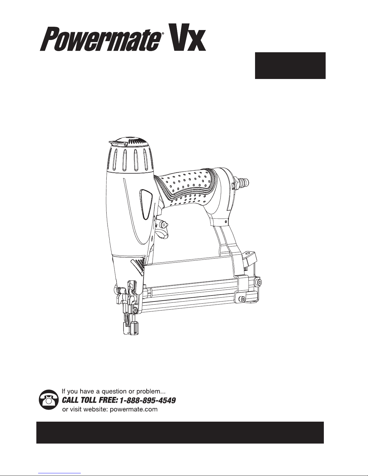
EXPLANATION OF THE NAILING
ACTION
•SINGLE ACTUATION MECHANISM:
First, press the safety against the wood; next, pull
the trigger to drive the fastener. After fastening once,
fastening will not be possible again until the trigger is
released and pressed again.
• CONTACT ACTUATION MECHANISM:
First, press the safety against the wood; next, pull the
trigger to drive the fastener. First. Pull the trigger; next,
press the safety against the wood to drive the fastener.
If the trigger is held back, a fastener will be driven each
time when the safety is pressed against the wood.
• FULL SEQUENTIAL ACTUATION MECHANISM:
First, press the safety against the wood; next, pull the
trigger to drive the fastener. Follow the same sequence
to continue driving fasteners.
GENERAL SAFETY RULES
WORK AREA
• KEEP THE WORK AREA CLEAN AND WELL LIGHTED.
Cluttered benches and dark areas increase the risks of
accidents.
•DO NOT OPERATE THE TOOL IN EXPLOSIVE
ATMOSPHERES, such as in the presence of flammable
liquids, gases, or dust. The tool creates a spark which
may ignite flammable liquids, gases or dust.
• KEEP VISITORS AWAY. Do not let visitors handle the
tool. All visitors should be kept safety away from work
area.
• NEVER ENGAGE IN HORSEPLAY WITH THE TOOL.
Respect the tool as a working implement.
PERSONAL SAFETY
• OPERATORS AND OTHERS IN WORK AREA MUST
WEAR SAFETY GLASSES WITH SIDE SHIELDS. When
operating the tool, always wear safety glasses with
side shields, and make sure others in work area wear
safety glasses, too. Safety glasses must conform to the
requirements of American National Standards Institute,
ANSI Z87.1 and provide protection against flying
particles both from the front and side.
The employer must enforce the use of safety glasses by
the tool operator and others in work area.
• ALWAYS WEAR EAR AND HEAD PROTECTION. Always
wear ear protection to protect your ears from loud noise,
Always wear head protection to protect your head from
flying objects.
• USE SAFETY EQUIPMENT. A dust mask, non-skid safety
shoes and a hard hat must be used for the applicable
conditions. Wear a full face shield if you are producing
metal filings or wood chips.
• DRESS PROPERLY. Do not wear loose clothing or
jewelry. Contain long hair. Keep your hair, clothing, and
gloves away from moving parts. Loose clothes, jewelry,
or long hair can be caught in moving parts and increases
the risk of injury.
• STAY ALERT, WATCH WHAT YOU ARE DOING AND USE
COMMON SENSE WHEN OPERATING A POWER TOOL.
Do not use tool while tired or under the influence of
drugs, alcohol, or medication. A moment of inattention
while operating the tool may cause serious injury.
• AVOID UNINTENTIONAL FIRING. Keep fingers away
from trigger when not driving fasteners, especially when
connecting the tool to the air supply.
• DO NOT OVERREACH. Keep proper footing and balance
at all times. Proper footing and balance enables better
control of the tool in unexpected situations.
• MAKE SURE AIR HOSE IS FREE OF SNAGS AND
OBSTRUCTIONS. DO NOT ATTACH AN AIR HOSE OR
TOOL TO YOUR BODY. Entangled or snarled hoses
can cause a loss of balance or footing in addition to
unintentional tool operation. Attach the hose to the
structure to reduce the risk of loss of balance of the hose
shifts.
TOOL USE AND CARE
•NEVER POINT TOOL AT YOURSELF OR OTHERS
IN WORK AREA. Always assume the tool contains
fasteners. Never point the tool at yourself or others,
whether it contains fasteners or not. If fasteners are
mistakenly driven, it can lead to severe injuries. Never
engage in horseplay with the tool. Respect the tool as a
working implement.
•KEEP FINGERS AWAY FROM TRIGGER WHEN NOT
DRIVING FASTENERS TO AVOID ACCIDENTAL FIRING.
Never carry the tool with finger on trigger since you
could drive a fastener unintentionally and injure yourself
or someone else. Always carry the tool by the handle
only.
• NEVER MODIFY OR ALTER A TOOL. Doing so may
cause it to malfunction and personal injuries may result.
• KNOW THIS TOOL. Read manual carefully, learn its
applications and limitations, as well as the specific
potential hazards related to this tool.