Bossong Boss G90W User manual

GAS POWERED BOSS G90W
NAILER OWNER’S MANUAL
To reduce the risk of possible injury. User must read this manual
before operate, handle, maintain this tool.
Please keep this manual in safe place for future reference.
Bossong S.p.A. - via Enrico Fermi nr .49/51 - 24050 Grassobbio - Bg - ITALY
Tel. 035 3846 011 - Fax 035 3846 012 - www.bossong.com - info@bossong.com

1. General warning
General safety warning
Tool safety warning
Fuel safety warning
Battery safety warning
Charger safety warning
2. Operation instruction
Load and unload the fuel cell
Load and unload the fastener
Depth of drive adjustment
Jam clearing for tool
Charge the battery and LED on tool and charger
3. Maintenance instruction
General maintenance
Lubrication and cleaning
Cold weather
4. Trouble shooting
5. Declaration of conformity
Table of content
3
3
3-4
5
5
5-6
6
6
6-7
7
7
8
9
9
9
9
9
10-11
12

1. General warning
operating, and servicing the tool. It is employer’s responsibility
to enforce user and all other nearby personnel at worksite to
wear eye protection when operating the tool.
It is recommended to wear ear protection near or at the job site
to prevent hearing damage.
Beware of the danger of entangled clothe and hair. Do not
dress loose clothing and jewelry at work. Keep you hair,
clothing, and gloves away from moving part of the tool.
This tool is not designed to be used in explosive atmosphere. The design of
this tool will generate spark and the exhaust will also cause possible
kind of environment. Please also not smoke while using or handling the
tool and fuel cell.
bottle. Follow the recycle instruction on the bottle.
Do not store the tool in temperature above 120°F(50°C). High temperature
in use, keep the tool from high temperature source or direct sun light.
The tool needs to be used in well ventilated area. Do not inhale the exhaust
or fume or the gas because they are potentially dangerous to human body.
Keep body balance when operating the tool, do not over reach.
Keep the tool, fuel, charger and battery out of the reach of children. The
tool is dangerous in the hand of untrained person.
Tool safety warning
Do not modify or repair the tool in any method other than the original
cause dangerous.
Never point the nozzle of the tool to anyone includes yourself. This tool is
self-contained with power source and will be dangerous if not use with
care. Always assume the tool is loaded with nail and fuel.
General safety warning

Do not drive this tool over materials that is too hard or too soft. Hard
material can ricochet nail and hurt people, soft material may be penetrate
lubrication. Use other lubrication may cause damage to the tool and the
risk of malfunction that will injure the operator.
Please keep the tool in clean condition, wipe off grease or oil after work. Do
not use any solvent based cleaner to clean the tool. It is possible the
solvent will deteriorate the rubber or plastic components on the tool.
Greasy handle and body will cause accidental drop of the tool and injury to
nearby person.
that is not compatible to the tool will cause jamming of the tool and injury
to operator or nearby person.
Do not use the tool to perform other job than designate function. Especially
not use the tool as a hammer, impact on the tool will increase the risk of
cracked body and accidental discharge of fastener.
Remove the fuel cell and battery before performing maintenance, repair,
cleaning and jam clearing.
Load the fastener at last to prevent unexpected danger of loading fuel cell
and battery.
Never use the tool if the trigger and safety or springs are damaged in any
way.
Hold the tool only by insulated gripping surfaces. Use only fasteners
designed for electrical cable installations. Inspect that the fastener has not
damaged the insulation of the electrical cables. A fastener that damages
Fuel safety warning
Use only the fuel cell recommended by the manufacturer. Read the Safety
Data Sheet to understand more of your fuel cell contents.
Recycle the empty fuel cell according to the local law. Do not attempt to
recharge the fuel cell or incinerate the empty fuel cell.
Do not expose the fuel cell or tools loaded with fuel cell under direct sun
light exposure. Prevent to put above items at temperature higher than
Do not puncture or attempt to open the fuel cell. The fuel cell contains
source of ignition.

Battery safety warning
Use only batteries that are supplied by the manufacturer.
Recycle the battery according to local law. Do not incinerate the battery of
attempt to puncture and crush the battery.
battery to rain or snow.
Do not expose the battery or tools loaded with battery under direct sun
light exposure. Prevent to put above items at temperature higher than
Do not allow direct contact of the battery nodes with metal or conductive
material.
Charge the batteries every 3 months even the tool is not used to prevent
battery over-discharged over time.
Charger safety warning
Do not use the charger in explosive atmosphere. The electrical device is not
designed to use in such environment.
Do not charge battery outdoors or in temperatures below 40°F (5°C).
Do not puncture or attempt to open battery case or cells.
charger under rain or snow.
Do not use the charger if the cord is damaged or the charger is defect.
Unplug the charger by pulling the adaptor unit, not by pulling the cord.
Do not cover the charger with anything.
Do not use a step up transformer or engine generator as the power source
of the charger.
the new battery.

Load and unload the fuel cell
Open the fuel cell door by pulling the
door and rotate.
Insert the fuel cell into the chamber.
Align the fuel cell nozzle to the fuel stem
on the tool.
Close the fuel cell door.
Load and unload the fastener
Connect to battery and fuel cell before
you load the fasteners. The tool had the
chance to cycle once when connected to
the battery. If you load the fastener
before the battery connected, the
fastener may be shoot out accidentally.
Point the nozzle away from any
trigger when loading the fastener.
To load the nail, slide in the nail strip
into the magazine until the nail strip passed the nail stopper.
Pull the pusher until it is beyond the stopper.
Release the pusher to engage the nail strip and feed it into the nozzle.
To unload the fastener from the magazine, press the release lever on the
pusher and tilt the tool to slide the nail strip to the rear end of the
magazine.
Unload the nail strip by press the nail stopper and slide out the nail strip.
For 3 steps magazine design, follow the same safety precaution
and continue with following steps
To load nail, pull the pusher to the rear until it is locked to the magazine at
rear position.
Slide nail strip into the magazine.
Release the pusher to push the nail into the nozzle.
To unload the fastener from the tool, pull the
pusher to the rear locking position. Slide the
nail out of the magazine.
2. Operation instruction

Depth of drive adjustment
This tool is equipped with tool free depth of
drive adjustment. Test the depth of drive on
scrap piece before you start your work.
Turn the knob to adjust the depth of drive.
desired depth of drive setting.
This tool is equipped with single sequential trigger system only.
To actuate the tool, depress the safety against the work piece, and then pull
the trigger.
To actuate the tool again, you will need to release the safety fully and
release the trigger before you repeat above procedure.
Make sure you are driving against work piece before you pull the trigger.
Jam clearing for tool
In the case of nail jam, disconnect the power source (fuel cell and battery)
before you perform any action.
If you tool is equipped with jam clear door, open the quick jam clear door
on the side to expose the jammed nail.
If your tool is equipped with removable nozzle, press the release button and
pull off the nozzle.
Remove the jammed nail with needle nose pliers or similar type of tool. Do
not use your hand to remove the nail.
Close the jam clear door or assemble back the nozzle after you clear the
jam.

Charge the battery and LED on tool and charger
There is battery comes along with the tool. It will
take 2 hours before the new battery can be fully
charged.
There will be no LED light when the charger is
connected to electric and no battery is on the
charger.
The LED on the charger will turn red when it is
charging a battery.
The other LED will turn green when the battery is
fully charged.
In the case of battery failure, the red and green LED will blink in sequence.
tool will turn green.
the LED indicator turns red, stop using the tool and replace the battery.

General maintenance
clean cloth to prevent accidental tool drop. Avoid to use solvent base cleaner
to clean the tool, certain solvent will damage or weaken the composite parts
of the tool.
Lubrication and cleaning
This tool should not need extra lubrication since the fuel already contains
some lubrication oil.
The combustion chamber and cylinder can be cleaned by applying
handle and 4 screws on the top cap to expose the internal component of
cylinder.
Cold weather
This tool is not suggested to be used in cold winter. The cold weather will
tool only at temperature above : -7°C(19°F).
Warning: disconnect the power source (fuel cell and battery) before
performing any maintenance
3. Maintenance instruction

4.Trouble shooting
symptom Counter measures
Red LED indicator light is on and
the tool did not operate.
Tool operates normally but did
pest.
before activate the trigger. If the tool did
the combustion chamber. Send to service
center near you.
Fan does not run and the indicator
light is red. with a
fully charged one.
the battery node with clean cloth.
center near you.
Battery does not accept charge
or the charger get hot when
charging.
the problem, the battery is damaged or
exhausted.
charger..
Charger get hot, make noise or
start to smoke be used any more. Unplug the charger
immediately and replace it with a new
charger.
fully depressed and the tool can
not be used.
track of the safety mechanism is sticky to
the dirt
build up. Clean the safety track. Repair or
replace the work contact element.
more nails.

symptom Counter measures
Tool will not cycle, the indicator
LED is green and the fan runs.
by removing the cap.
center near you.
Tool operate normally, but no
nail is driven change to correct nail spec.
before use.
with the nail strip. Adjust to fully engage-
ment.
Combustion chamber is not
returning to start position. dirty.
Check the work contact element and repair
orreplace it. Clean the safety track.
Driver did not return to initial position, miss
Tool appears to be loosing
power.
For failure other than above situation, please stop using the tool and contact your local
dealer for service.

VIII Page 1 of 1
Gas nailer
1. Fastener type and size
zNailshank :2.9~3.3mm
zNaillength :50~90mm
zCollation type : paper collation
zNail strip angle : 34°
zMagazine capacity : 2nail strips, or 60 nails
2. Tool spec
zModel number : BOSS G-90W
zType of tool : Gas Nailer for wood
zDimension(LxWxH) : 374 ×108 ×378mm
zWeight of tool : 3.42 Kg(7.5lb) with battery
zShot limit : 1000 shots/hour
zDriverate :2-3shots/sec
zRated input : 220-240 Vac, 50 Hz,1A
zCharge time of battery : 120mins
zBattery voltage : 6 Volt
zShots per Charge : 4500shots
zShots per fuel : 1200shots
zUsable temperature : -7C°~50C°
zApplications & suitability : Structure building. Framing.
zActuating system ( safety joke installed) : full sequential only
zTrigger device : Finger activated trigger.
3. Noise and vibration data
zNoise characteristic values in accordance with EN 12549+A1
zA-weighted sound pressure level at workstation : 94.5 dB
zA-weighted sound power level : 96.4 dB
zPeak C-weighted instantaneous sound pressure level at workstation: < 130 dB
zVibration value according to ISO 8662-11+A1 : 3.36 m/s2
zMeasurement uncertainty (Standard) : 1.68 m/s2
Declaration of Conformity
We Bossong S.p.A.
Via Enrico Fermi 49/51
24050 Grassobbio (Bergamo) ITALY
Tel. +39 035 3846 011
declare under our sole Gas Nailer for wood BOSS G-90W
responsibility that the
conforms with the directive 2006/42/EC (MSD),2006/95/EC (LVD),2004/108/EC (EMC)
and the standards 2011/65/EU (RoHS)
EN ISO 12100,EN 792-13+A1,
EN 12549+A1,ISO8662-11+A1
EN 60745-1,EN 60745-2-16,EN 55014-1,EN 55014-2+ A2
EN 61000-3-2,EN 61000-3-3,EN 50581
EN 60335-1,EN 60335-2-29,EN 62233
EN 61558-1,EN 61558-2-1
Numero di serie: Firmato:
Andrea Taddei – Direttore generale

Repère Code Français English Deutsch Español Romana
101 12B02577 déflecteur deflector Leitblech Deflector Deflector
102 12B02539 Filtre Filter Filter Filtro Filtreaza
103 12B00780 Boulon Bolt Kopfschraube Perno Bolt
104 12B00834
j
ointplat O‐ring O‐ring Junta Garnitura
105 12B02540 Bague Collar Ring Manguito Inel
106 12B02541 tête Cap Deckel Tapa Capac
107 12B02542 Crochet Bracket Haken Gancho Carlig
108 12B02543 Anti‐parasite Highvoltagecableset Hochspannungs‐Kabel‐Set altovoltajejuegocables cabludeînaltătensset
109 12B02544 Bougieallumage Spaklerunit WunderkerzeEinheit unidaddebengala sparklerunitate
110 12B02545 Moteur Motor Motor Motor Motor
111 12B02546
j
oint O‐ring O‐ring Junta Garnitura
112 12B02547 Vis screwSchraube Tornillo Surub
113 12B02548 socle rearplate sockel Zocalò Bazà
114 12B02549 Crochet Bracket Haken Gancho Carlig
115 12B02550 Manchonmoteur Sleevemotor Muffe Manguito Manchon
116 12B02551 rondelle Ring Scheibe Arandela Saiba
117 12B02552 Tige Stem Stängel Varilla Regleta
118 12B02553 Culasse Endcapcomb,chamberZylinderkop
f
recámara pelviană
119 12B02554
j
oint O‐ring O‐ring Junta Garnitura
120 12B02555
j
oint O‐ring O‐ring Junta Garnitura
121 12B02556
j
oint O‐ring O‐ring Junta Garnitura
122 12B02557
j
oint O‐ring O‐ring Junta Garnitura
123 12B02558 Vis screwSchraube Tornillo Surub
124 12B02559 Ventilateur Coolingfanassembly Lüfter Ventilador Ventilator
125 12B02560 Vis screwSchraube Tornillo Surub
126 12B02561 guide Driverunit Führer Guia Ghidaj
127 12B02562 Vis screwSchraube Tornillo Surub
128 12B02563 Chambredecombsup Uppercomb.chamber SuperiorBrennkammer cámaradecomb.supsuperiorcamereiardere
129 12B02564 PACKING
130 12B01822 Vis screwSchraube Tornillo Surub
131 12B02565 rondelle Ring Scheibe Arandela Saiba
132 12B02566 Chambredecomb Combustionchamber Brennkammer Camaradecombustion Camereideardere
133 12B02567 Goupille Pin Stift Clavija Zavor
134 12B02568
j
oint O‐ring O‐ring Junta Garnitura
135 12B02569
j
oint O‐ring O‐ring Junta Garnitura
136 12B02570
j
ointdepiston PistonO‐ring KolbenO‐ring Juntadelpiston Garnitura
137 12B02571 guide Driverunit Führer Guia Ghidaj
138 12B02572 amortisseur Bumper Puffer amortiguador Amortizor
139 12B02573 cylindre cylinder Zylinder cilindro Cilindru
140 12B02574 amortisseur Bumper Puffer amortiguador Amortizor
141 12B02575 Ressortdesécurité Safetyspring sicherungsFeder Muelledeseguridad Arcdesiguranta
142 12B02576 socle rearplate sockel Zocalò Bazà
143 12B02578 EXHAUST BAFFLE
144 12B02579 Vis screwSchraube Tornillo Surub
145 12B02580 Valve Valve Ventil Valvula Valva
146 12B02581 CLEANER
147 12B02582 déflecteur deflector Leitblech Deflector Deflector
148 12B02663 Vis screwSchraube Tornillo Surub
149 12B02583 Vis screwSchraube Tornillo Surub
150 12B02584 nez Nose Nase Morro Nas
151 12B02585 sécuritéBSafetyBSicherheitBSeguridadBSigurante

152 12B02586 écrou Screwnut Mutter Tuerca Piulita
153 12B02587 axed'ajustement Adjustaxie Achseanpassung EjedeAjuste Axadeajustaje
154 12B02588 sécuritéASafetyA Sicherungeinheit Unidaddeseguridad Sigurante
155 12B02589
j
oint O‐ring O‐ring Junta Garnitura
156 12B02590 poussoir trigger Ausloser pulsador secundor
157 12B02591 SécuritéCgauche SafetyCgauche SicherungClinks SeguridadCalaizquierda SigurantaCstanga
158 12B02592 amortisseur Bumper Puffer amortiguador Amortizor
159 12B02593 Manche Shaft Grif
f
Mango Manipula
160 12B02594
j
oint O‐ring O‐ring Junta Garnitura
161 12B02595 SécuritéCdroite SafetyCright SicherungCrechts SeguridadCaladerecha Sigurantadreapta
162 12B02596 Tigedesécurité Safetyrod Sicherheitstange Barradeseguridad Tijadesiguranta
163 12B02597 Ressortdesécurité Safetyspring sicherungsFeder Muelledeseguridad Arcdesiguranta
164 12B02598 amortisseur Bumper Puffer amortiguador Amortizor
165 12B02599 Embout Protectivecasing Endabdeckung Contera Sfat
166 12B02600 anneau Ring Scheibe Arandela Saiba
167 12B02601 Entretoise Spacer Abstandshalter Tirante Spacer
201 12B02602 ressort Spring Feder Muelle Arc
202 12B02603 gâchette Trigger Drücker Gatillo Opritor
203 12B02604 Sécurité Safety Sicherung Seguridad Siguranta
301 12B02605 corps Body Gehause Cuerpo Corp
302 12B02606 tête Cap Deckel Tapa Capac
303 12B02607 Insert Capnut Einsatz Inserto Insera
304 12B02608 Crochet Bracket Haken Gancho Carlig
305 12B02609 Boulon Bolt Kopfschraube Perno Bolt
306 12B02610 Couvresécurité Safetycover Sicherungsdeckel Tapaderadeseguridad Capacdesigurante
307 12B02611 Couvercle Cover Deckel tapadera Capac
308 12B01138 Vis screwSchraube Tornillo Surub
309 12B02612 Goupille Pin Stift Clavija Zavor
310 12B02613 Actionneurdecarburant Fuelactuator AntriebKraftstof
f
Actuadordecombustible Actionaredecomb.
311 12B02614 Douille Bush Buchse Enchufe Priza
312 12B00048 Boulon Bolt Kopfschraube Perno Bolt
313 12B02615 PoignéeA HandleAGriffAPicaporteA MânuiA
314 12B02616 Boulonpoignée HandleBolt Griffkopfschraube Pernoparapicaporte Boltdimânui
315 12B02617 Entretoise Spacer Abstandshalter Tirante Spacer
316 12B02618 Crochet Bracket Haken Gancho Carlig
317 12B02619 Boulon Bolt Kopfschraube Perno Bolt
318 12B02620 Boulon Bolt Kopfschraube Perno Bolt
319 12B02621 guide Driverunit Führer Guia Ghidaj
320 12B02622 Unitécentrage PCBASSEMPLY Zentriereinheit Unidaddecentrado centrare unitate
321 12B02623 Boulon Bolt Kopfschraube Perno Bolt
322 12B02624 levier Lever Hebel Palanca Impagatot
323 12B01595 rondelle Ring Scheibe Arandela Saiba
324 12B02626 Crochet Bracket Haken Gancho Carlig
325 12B02627 BATTERY NODE
326 12B00046 Boulon Bolt Kopfschraube Perno Bolt
327 12B02628 Voyant Ledcover Anzeige Piloto văzând
328 12B01054 Vis screwSchraube Tornillo Surub
329 12B02629 PoignéeB HandleBGriffBPicaporteB MânuiB
330 12B00787 rondelle Ring Scheibe Arandela Saiba
331 12B02630 Vis screwSchraube Tornillo Surub
333 12B02631 ressortASpringA FederA MuelleAArcA
334 12B02632 Piècedeliaison Linkrod Stutzen piezadeconexión piesădeconectare
335 12B02633 Stoppeur Stopper Vorstopper Zurcidor Opritor
336 12B02634 ressort Spring Feder Muelle Arc
340 12B02635 Vis screwSchraube Tornillo Surub
341 12B02636 ressort Spring Feder Muelle Arc
342 12B00015 ressort Spring Feder Muelle Arc
401 12B02637 tête Cap Deckel Tapa Capac
402 12B02638 Crochet Bracket Haken Gancho Carlig
403 12B00567 tête Cap Deckel Tapa Capac
404 12B02639 Rondelleplate Flatwasher Scheibe Arandela Saiba
405 12B01129 Vis screwSchraube Tornillo Surub
406 12B02640 Axe Axie Achse Eje Axa
407 12B02641 ressort Spring Feder Muelle Arc
408 12B02642 Vis screwSchraube Tornillo Surub
409 12B02643 Crochet Bracket Haken Gancho Carlig
410 12B02644 ressort Spring Feder Muelle Arc
411 12B02645 STEEL CHANNEL
412 12B02646 Boulon Bolt Kopfschraube Perno Bolt
413 12B02647 Vis screwSchraube Tornillo Surub
414 12B02648 magasinA MagazineA MagazinA AlmacenAMagazieA
415 12B02649 Couvercle Cover Deckel tapadera Capac
416 12B00108 Vis screwSchraube Tornillo Surub
417 12B02651 plaqueavant Driveguidecover schaltlatt placa placa
418 12B02652 Joint Gasket O‐ring Junta Garnitura
419 12B02653 Vis screwSchraube Tornillo Surub
420 12B02650 ressort Spring Feder Muelle Arc
421 12B00707 Elementroulant Rollingpiece Rollendesmaterial Piezarodando materialrulant
422 12B02654 Couvercle Cover Deckel tapadera Capac
423 12B02655 Goupille Pin Stift Clavija Zavor
424 12B02656 protection Protection Sicherheit Proteccion Sigurante
425 12B02657 ressort Spring Feder Muelle Arc
426 12B00676 Vis screwSchraube Tornillo Surub
427 12B00368 PU RETAINER
428 12B00096 URETHANE RETAINER
429 12B02658 poussoir trigger Ausloser pulsador secundor
430 12B02659 SQUARE UNTS
431 12B00161 pivot Pivot Drehachse Pivote Pivot
Table of contents
Other Bossong Nail Gun manuals
Popular Nail Gun manuals by other brands
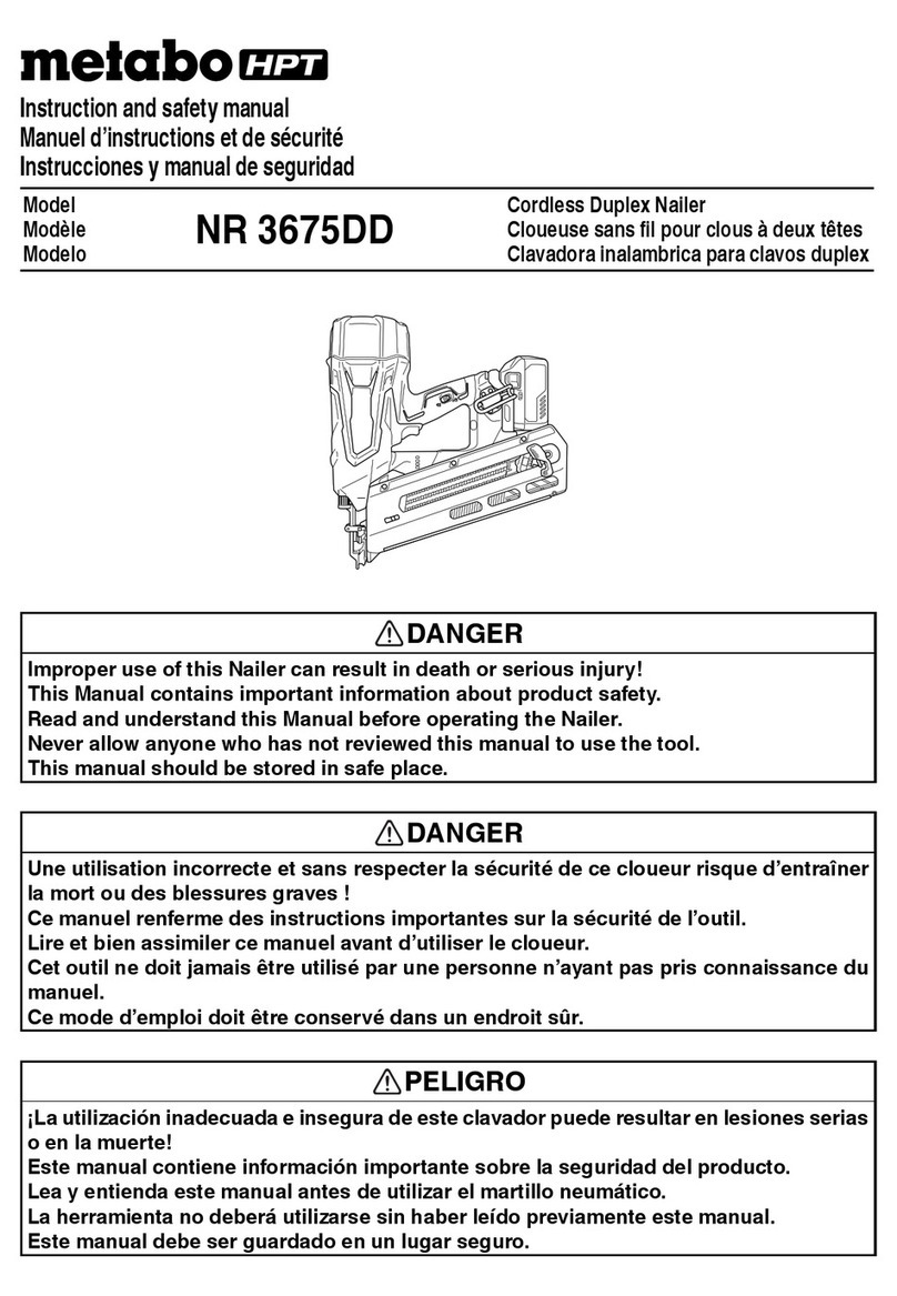
Metabo HPT
Metabo HPT NR 3675DD Instruction and safety manual
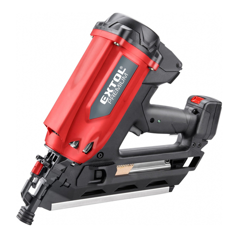
EXTOL PREMIUM
EXTOL PREMIUM 8894580 Translation of the original user manual
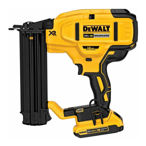
DeWalt
DeWalt XR Li-Ion DCN680D2 Original instructions
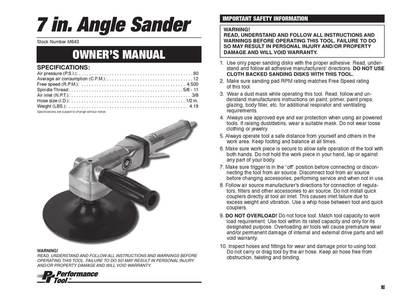
Performance Tool
Performance Tool M643 owner's manual
Hitachi
Hitachi VH650 - Fencing Nailer, Full Head instruction manual

Parkside
Parkside PET 25 B1 Operation and safety notes

