PowerQuick PQ 500-1 User manual

1. WARRANTY..........................................................................................................................................1
2. PERSONAL SAFETY ...........................................................................................................................1
3. SPECIFICATIONS ................................................................................................................................2
4. BATTERY PACK AND CHARGER ......................................................................................................4
4.1. USE INSTRUCTIONS ..............................................................................................................................5
4.2. BATTERY WARRANTY...........................................................................................................................5
4.3. BATTERY DISPOSAL .............................................................................................................................5
5. CERTIFICATION/MAINTENANCE REQUIREMENTS.........................................................................6
6. CERTIFIED MAINTENANCE FACILITIES ...........................................................................................6
7. DEFINITIONS........................................................................................................................................6
8. USE INSTRUCTIONS...........................................................................................................................8
8.1. LOADING INSTRUCTIONS.......................................................................................................................9
8.2. CONNECTING THE POWER SUPPLY......................................................................................................10
8.3. CONNECTING TO THE ASCENDER ........................................................................................................10
8.4. ABOUT THE POWER SUPPLY...............................................................................................................10
8.5. CLIMBING WITH THE ASCENDER...........................................................................................................11
8.6. EMERGENCY POWER OFF/RESET ........................................................................................................11
8.7. REMOTE CONTROL.............................................................................................................................11
8.8. BRAKE FUNCTION...............................................................................................................................13
8.9. MANUAL BRAKE RELEASE..................................................................................................................14
8.10. ATTACHING THE LOAD AND CHECKING LIFT CAPACITY ......................................................................14
8.11. THERMAL PROTECTION ....................................................................................................................15
8.12. HORIZONTAL APPLICATIONS .............................................................................................................15
9. POWERQUICK POWERED ASCENDER SYSTEM MAINTENANCE...............................................16
9.1. GENERAL MAINTENANCE....................................................................................................................17
9.2. CLEANING..........................................................................................................................................17
SAFE DEPLOYMENT OF THE POWERQUICK ASCENDER...................................................................19
10. OPERATION REQUIREMENTS.......................................................................................................19
10.1. REQUIRED ITEMS..............................................................................................................................19
10.2. REQUIRED PRACTICES .....................................................................................................................19
11. EQUIPMENT AND APPLICATION OF POWERQUICK SYSTEMS................................................20
Contents

11.1. FALL PROTECTION BASICS AND JOB SITE SAFETY ............................................................................20
11.2. EQUIPMENT......................................................................................................................................21
12. USE REQUIREMENTS.....................................................................................................................21
12.1. STRUCTURE AND ANCHORAGE POINTS -EXISTING STRUCTURE .........................................................21
12.2. STRUCTURE AND ANCHORAGE POINTS -PURPOSE BUILT SUSPENSION RIGS .....................................22
13. OPERATIONAL REQUIREMENTS..................................................................................................22
13.1. SURFACE AREA AND WEIGHT...........................................................................................................22
13.2. ELECTRICAL HAZARDS &LOCKOUT/TAGOUT ....................................................................................22
13.3. CORROSIVE ENVIRONMENTS.............................................................................................................23
13.4. ROPES AND RIGGING........................................................................................................................23
14. EMPLOYEE SELECTION AND CAPABILITIES..............................................................................24
14.1. DUTIES OF LEVEL 1ROPE ACCESS WORKERS ..................................................................................25
14.2. DUTIES OF LEVEL 2ROPE ACCESS TECHNICIAN................................................................................25
14.3. DUTIES OF ROPE ACCESS ATTENDANT (MAY BE LEVEL 1, 2, OR 3)....................................................25
14.4. DUTIES OF LEVEL 3ROPE ACCESS SUPERVISOR...............................................................................25
15. TRAINING.........................................................................................................................................26
15.1. LEVEL 1WORKER............................................................................................................................26
15.2. LEVEL 2TECHNICIAN .......................................................................................................................26
15.3. LEVEL 3SUPERVISOR ......................................................................................................................26
16. 3.0 INDUSTRIAL ROPE ACCESS SITE CHECKLIST ....................................................................27
17. DETAILED INSPECTION REQUIREMENTS FOR EQUIPMENT....................................................28
18. REFERENCED PUBLICATIONS .....................................................................................................34
SERVICE CONTRACT & MAINTENANCE OPTIONS ..............................................................................36
NOTES..........................................................................................................................................................2

EU DECLARATION OF CONFORMITY (for Annex IV Machinery)
In accordance with Council Directive 98/37/EC
Conforming Machinery:
PowerQuick Model 500-1 Powered Personal Ascender for technical rope access work
positioning and rescue operations
Manufactured at:
PowerQuick Concepts, Inc. 6267 Millett Ave, Sterling Heights MI 48312
We hereby declare, that all major safety requirements concerning CE Mark Directive 93/68/ ECC, 98/37 EC
Machinery Safety, 89/366 Electromagnetic CoTRL Compliance Compatibility y, and 73/23 ECC Low Voltage
Equipment published by the member states of the ECC Commission –insofar as they apply to this product –have
been fulfilled.
Harmonized Standards
referenced;
EN 292-1: 1991, EN 292-2:1992, EN 418:1002, EN 953:1997, EN 1050:1996, EN ISO
14982:1998, EN 50260-1:2002, ED 418:1992, prEN1005-1: 1996, prEN1005-2: 1996, prEN
1808:1998, prEN12927-7:1998, prEN 12937:1997,
Specifications with
which Conformity is
Declared:
BS 7985: 2002 British Standard Code of Practice The use of rope access methods for
industrial purposes.
Guidelines on the use of rope access for industrial purposes; Industrial Rope Access
Trade Association (IRATA) 2000
AS/NZS 4488.1,2 Australian/New Zealand Standard & AS/NZS 1891
US Federal Spec RR-S-001301 Safety Equipment, Climbing: 22 June 1967
CAN.CSA-C22.2 # 157-92 Intrinsically Safe and Non-Incendive Equipment for use in
Hazardous Environment Locations for Class I, Division 2
CAN/CSA Z259.2.3-99 Descent Control Devices
MIL–STD- 1474 Noise Limits
MIL–STD- 1212 Safety Equipment
MIL–STD- 1433b Climber Sets
US 29 CFR Non-Mandatory Guidelines for Complying with 1926.502(d) –126, Subpart M
APP C
US 29 CFR 1910.268 Special Industries
B.C. Reg. 585/77 8.100 Canada Health & Safety Code
Notified Body holding
the technical file:
TRL Compliance
Moss View, Nipe Lane, Up Holland, West Lancashier, WN8 9PY, UK
Tel: +44 (0) 1695 556666
Authorized
Representative:
PowerQuick UK
The Bull Pen
Castle Square
Bletchingley
RH1 4LD, United Kingdom
Tel: +44 020 8879 3541
Date of Issue:
August 10, 2007
M. Cathryn Jacobson, CEO, PowerQuick Concepts, Inc.

P
PQ
Q
5
50
00
0-
-1
1
W
Wi
it
th
h
W
Wi
ir
re
el
le
es
ss
s
R
Re
em
mo
ot
te
e
C
Co
on
nt
tr
ro
ol
l
P
PQ
Q
5
50
00
0-
-
T
TR
R
W
Wi
it
th
h
W
Wi
ir
re
el
le
es
ss
s
a
an
nd
d
W
Wi
ir
re
ed
d
R
Re
em
mo
ot
te
e
C
Co
on
nt
tr
ro
ol
l

PowerQuick Powered Ascender (1) PQ500-1 1-Sep-15
PowerQuick Powered Personnel Ascender
Operations Manual & System Information for
Work Positioning Use and Safety
READ THIS ENTIRE MANUAL BEFORE OPERATING THE POWERQUICK ASCENDER.
There are no user serviceable parts in the PowerQuick. The unit should be sent to
PowerQuick Concepts, Inc.Products or an authorized service facility for maintenance and
repairs.
When using this device, basic safety precautions should always be followed to reduce the
risk of fire, electric shock, and injury to persons and/or property, including the following:
The PowerQuick is designed for work positioning. It is not a fall arrest device and is
required to always be used with a secondary fall arrest system consisting of a safety line
and lanyard connected to the operator’s approved harness for fall arrest protection.
Read Section 18 on Referenced Publications. Operators are required to review and adhere
to these and other requirements that may pertain to your particular industry or operations.
This list is not inclusive. It is the user’s responsibility to be aware of these additional
requirements.
1. Warranty
THERE ARE NO WARRANTIES OF MERCHANTABILITY OR OF FITNESS FOR A PARTICULAR PURPOSE, or otherwise
which extend beyond the description enclosed in this document and those expressly stated in these conditions.
PowerQuick Concepts, Inc. warrants to the Purchaser that the products being sold hereunder have the capacities and rating
set forth in the product specifications and are free from defects in material and workmanship for a period of one year or 3.8
miles/6K (20,000 rotations measured by the odometer on the unit) of use, whichever comes first. The Ascender must then
undergo inspection and certification by a PowerQuick Concepts, Inc. qualified maintenance facility as discussed in Section 5.
Once recertified, the warranty is extended to the next certification period.
The seller does not warrant equipment or accessories manufactured by others, but will submit to buyer upon request the
manufacturer’s warranty, if any, and will assist buyer in securing the benefit of such warranty if inspection proves such parts
defective. In no event, whether as a result of breach of warranty or otherwise, shall the seller be liable for special or
consequential damages. No warranty is included against any consequential damages arising from any defect. Considering
the widely varying conditions under which our products are used we cannot be and are not bound, and no person is
authorized to bind us, by any further warranty whatsoever, express or implied.
2. Personal Safety
Do not operate if under the age of 18. Do not operate unless YOU HAVE BEEN TRAINED by a certified
trainer. Dangerous in the hands of untrained users.
For information on PowerQuick Concepts, Inc. approved trainers contact your distributor.
Stay alert, watch what you are doing and use common sense when operating the Power Quick Ascender.
Do not use while tired or under the influence of drugs, alcohol, or medications. A moment of inattention while
operating may result in serious personal injury.
Dress properly. Do not wear loose clothing or jewelry. Contain long hair. Keep your hair, clothing, and
gloves away from moving parts. Loose clothes, jewelry, or long hair can be caught in moving parts.
Use only accessories that are recommended by the manufacturer for your model. Accessories that may be
suitable for one model may become hazardous when used on another. See the approved Accessories List
located at the back of this manual.

PowerQuick Powered Ascender (2) PQ500-1 1-Sep-15
Carefully read the maintenance and certification instructions. Check for misalignment, loosening or
binding of moving parts, breakage of parts, and any other condition that may effect the operation. If
damaged, have the ascender serviced before using. Many accidents are caused by poorly maintained
equipment.
Do not immerse this product in water, for example, a lake, swimming pool or water puddle. May result in
serious personal injury.
Do not connect or disconnect battery cable from either the PQ 500 or battery in a potentially explosive
environment.
Limit climb or descend to 200 foot intervals. Allow 15 to 30 seconds for unit to cool during long climbs or
descents.
Operation with excessive loads and low battery voltage may cause clutches to overheat and smoke. It is
the operator’s responsibility to insure that the PQ 500 is not overloaded.
Keep ascender clean of debris. Inspect and clean rope prior to each use and periodically during use. This is
particularly important when the ascender is used in dirty environments.
3. Specifications
The PQ500-I and the PQ500-TR (Tower Version) are the same except that the TR unit is equipped with a wired as
well as a wired remote control. This allows the unit to be used in areas where radar, EMF or other elements may
interfere with standard wireless operations. The TR unit can also be equipped with an optional bite switch for
hands free operation. The following specifications apply to both versions of the PowerQuick Ascender.
PQ 500-1 Powered Ascender
Operational Features
Compatible with standard climbing gear (Must be used in accordance with manufacturers
instructions meet applicable requirements and regulations)
Use with 1/2-in (12.7mm) static (low stretch) kernmantle rope (recommend New England, Blue
Water, PMI brand ropes) (Note: Care and maintenance of rope required per manufacturer’s
instructions.)
Weight: 28 pounds (13 kg)
Dimensions: 14 x 14 x 18 (35 x 35 x 45 centimeters)
Lifting capacity: 500 pounds/227 kg; gross load 550 lbs (250kg) includes PQ 500 and battery pack.
Designed for use by one person, for work positioning and/or moving tools and materials
Easily carries 2 people for rescue applications
Lifting speed: 0.7 ft/second (.22m/sec)
Powered descent speed: up to 1 ft (.9meter)/sec (varies with weight)
Can be operated using wireless remote or manual control
Remote range up to 200 ft (61 meters) The range may be affected by local interference from cell
towers or other electrical signals.
TR unit equipped with separate wired remote for use in areas with electrical interference. May
include optional bite switch.
May be used with a spreader bar and work seat or bosun’s chair.
May be used with extra batteries to increase climbing time.
Can be operated with gloves and protective clothing
Safety Features
Tested to a safety factor of 5 for structural and a factor of 2 operationally
Temperature sensor shuts unit down in event of hot motor.
Interlock switch on cover ensures that unit will not operate if rope handler cover is not properly
closed.
Remote control overrides local control
Rope cannot be removed from ascender when it is under a load.
Auto-braking in hands-off position provides for both locked-off and emergency or panic lockoff. No
force need be applied for panic lockoff.
Emergency Stop Button: cuts power to unit

PowerQuick Powered Ascender (3) PQ500-1 1-Sep-15
Load limiter: Prevents lifting of load in excess of 900 lbs (409 kg).
Auto-braking in hands-off position provides for emergency stop.
Static Load/Stationary holding capacity: 1,100 lbs (500kg)
Dynamic load capacity: 2,500 lbs (1,136 kg)
Forward reverse power control
Palm Interlock must be engaged to start unit
Low voltage sensor detects low battery voltage and shuts unit down. PQ 500 level is 26 VDC,
No pinch points
No sharp edges, points, etc., capable of puncturing or cutting the skin
Accessible surface temperature do not exceed 65° C
Rotating parts protection
No shock hazard
Use restrictions
Not to be used after shock load of in excess of 1,200 lbs (544kg).
Not to be used after drop greater than 4 ft (1.2meters) onto hard surface
(Must undergo inspection and recertification after these events)
Environmental conditions
Moisture: May be used in wet weather. However; do not immerse this product in water, for example, a
lake, swimming pool or water puddle. May result in serious personal injury and damage to the machine.
No negative affect from corrosive environments, e.g. salt water or spray. Should be cleaned after use in
these environments
Dust, sand, dirt, mud etc: .The ascender can be used in oily, or dirty conditions without affecting the
performance. However; for rope safety, keep ascender clean of heavy debris. Inspect and clean rope
prior to each use and periodically during use.
Power Supply
NiMH Rechargeable Battery: 36vdc, 30 amp, 360 amp-minutes discharge to 25 vdc.
Climbing Time: 500 to 600 feet (152-182m) per charge.
Battery Pack Weight: 14 lbs.
Operating Temperature Range: 32˚ F to 113˚F (0˚ C to +45˚ C). When working in extreme cold keep
the batteries warm (store in the cab of your truck) when not in use. Once in use internal heat is
generated. An insulated battery sleeve is also available.
Designed to withstand 4-ft (1.2meters) drop on hard surface.
Battery life: approximately 800 charge/discharge cycles (temperatures extremes can affect battery life)
Battery is protected with an internal fuse that will disable the battery in event of a short circuit. The
standard battery uses a blade type 40 amp fuse.
The battery cable is 6 foot long with a threaded connector on either end. The cable connectors are such
that it is impossible to connect the cable backwards.
Charger
Use to charge PowerQuick NiMH battery packs only
Input: 115/230VAC 60/50 Hz 1.8/1.0A
Output 36VDC/2.6A Continuous
1. Personal Safety
Do not operate if under the age of 18. Do not operate unless YOU HAVE BEEN TRAINED by a certified
trainer. Dangerous in the hands of untrained users.
For information on PowerQuick, Inc. approved trainers contact your distributor.
Stay alert, watch what you are doing and use common sense when operating the Power Quick
Ascender. Do not use while tired or under the influence of drugs, alcohol, or medications. A moment of
inattention while operating may result in serious personal injury.
Figure 1
Battery
Charger

PowerQuick Powered Ascender (4) PQ500-1 1-Sep-15
Dress properly. Do not wear loose clothing or jewelry. Contain long hair. Keep your hair, clothing,
and gloves away from moving parts. Loose clothes, jewelry, or long hair can be caught in moving parts.
Use only accessories that are recommended by the manufacturer for your model. Accessories that may
be suitable for one model may become hazardous when used on another. See your distributor for the
approved Accessories List
Carefully read the maintenance and certification instructions. Check for misalignment, loosening or
binding of moving parts, breakage of parts, and any other condition that may effect the operation. If
damaged, have the ascender serviced before using. Many accidents are caused by poorly maintained
equipment.
Do not immerse this product in water, for example, a lake, swimming pool or water puddle. May result
in serious personal injury.
Do not connect or disconnect battery cable from either the PQ 500 or battery in a potentially explosive
environment.
Limit climb or descend to 200 foot intervals. Allow 15 to 30 seconds for unit to cool during long climbs
or descents.
Operation with excessive loads and low battery voltage may cause clutches to overheat and smoke. It is
the operator’s responsibility to insure that the PQ 500 is not overloaded.
Keep ascender clean of debris. Inspect and clean rope prior to each use and periodically during use. This
is particularly important when the ascender is used in dirty environments.
4. Battery Pack and Charger
WARNING: Before using battery charger read all instructions
and cautionary markings on (1) battery charger, and (2)
battery pack.
The PowerQuick Ascender battery pack features Nickel-Metal
Hydride (NiMH) rechargeable batteries. They offer up to 40% more
capacity (per volume) than Nicad. They are also more environmentally
friendly. The biggest advantage of NiMH over Nicad is their ability to
accept a charge at any time without suffering from the "memory effect".
The best way to charge NiMH batteries is with regular charging. Do
not allow NiMH batteries to discharge below 25 VDC.
Sustained high-current overcharge and cell polarity reversal (during
charge) are destructive to NiMH batteries. It is essential to terminate
charge when the cell is full. If this is not done, the temperature and
pressure within the cell will rise quickly as the charging current is
dissipated as heat. NiMH cells have internal vents, which will open to
allow gas to escape and prevent explosion of the cell.
Cautions-
Use only the charger that accompanies your product or a
direct replacement. Do not substitute any other charger. May
result in battery damage and/or serious injury.
Do not disassemble the battery or the charger or operate the
charger if it has received a sharp blow, been dropped or
otherwise damaged in any way. Replace damaged cords or
plugs immediately. Incorrect reassembly or damage may
result in electric shock or fire.
Do not recharge battery in damp or wet environment. Do not
expose charger to rain or snow. If battery case is cracked or
otherwise damaged, do not recharge. Battery short or fire
may result.
External Appearance-The cell/battery shall be free from
cracks, scars, breakage, rust, discoloration, leakage and
deformation.
NI-MH BATTERY CHARGER SPECIFICATIONS
MODEL
8208N3
InputVoltage
115VAC-230VAC
OutputVoltage
44VDC (30cellsx1.2V)
Efficiency
Min.81%
OutputCurrent
2.6A±0.1A
TrickleChargeCurrent
500-600mA-adjustable
-?V
6mV±2mV/cell, 120mV–240mV
?T/?t
1.0ºC ±0.3ºC/min
Maximumstartchargetemperature
45ºC±5%
Minimumstartchargetemperature
0ºC ±5%
Tmax
48±5%-adjustable
Maxchargetime
6hours-adjustable
Vmax
>52.5V
Noloadvoltage
59.5V±0.5V
Undervoltagetricklecurrent
0.5A±0.1A(?26V)
OperatingTemperature
0ºC-40ºC
StoreAmbientTemperature
-10ºC -70ºC
Measurement
140mm(L)×90mm(W)×50mm(H)
Weight
0.8kg
Approval
CE,TUV, UL,PSE,EMI,CB, CSA
Output Detection:
1. Short Circuit Detection
2. Output Voltage/ Current Limit
3. Reverse Power Protected
4. Overheat Detection
5. Charging Time Limit

PowerQuick Powered Ascender (5) PQ500-1 1-Sep-15
Reverse charging is not acceptable. PowerQuick Battery Charger is equipped with a circuit to prevent reverse
charging.
Charge before use.
Do not charge/discharge with more than the specified current.
Do not short circuit the cell/battery.
Do not incinerate or mutilate the cell/battery.
The life expectancy may be reduced if the cell/battery is subjected to adverse conditions, like extreme temperature,
deep cycling, and excessive overcharge/over-discharge.
Store the cell/battery in a cool dry place.
Keep away from children. If swallowed, contact a physician at once.
Avoid using this product during an electrical storm. There may be remote risk of electric shock from lightning.
Use with PowerQuick Ascender only. DO NOT use to power other devices
4.1.Use Instructions
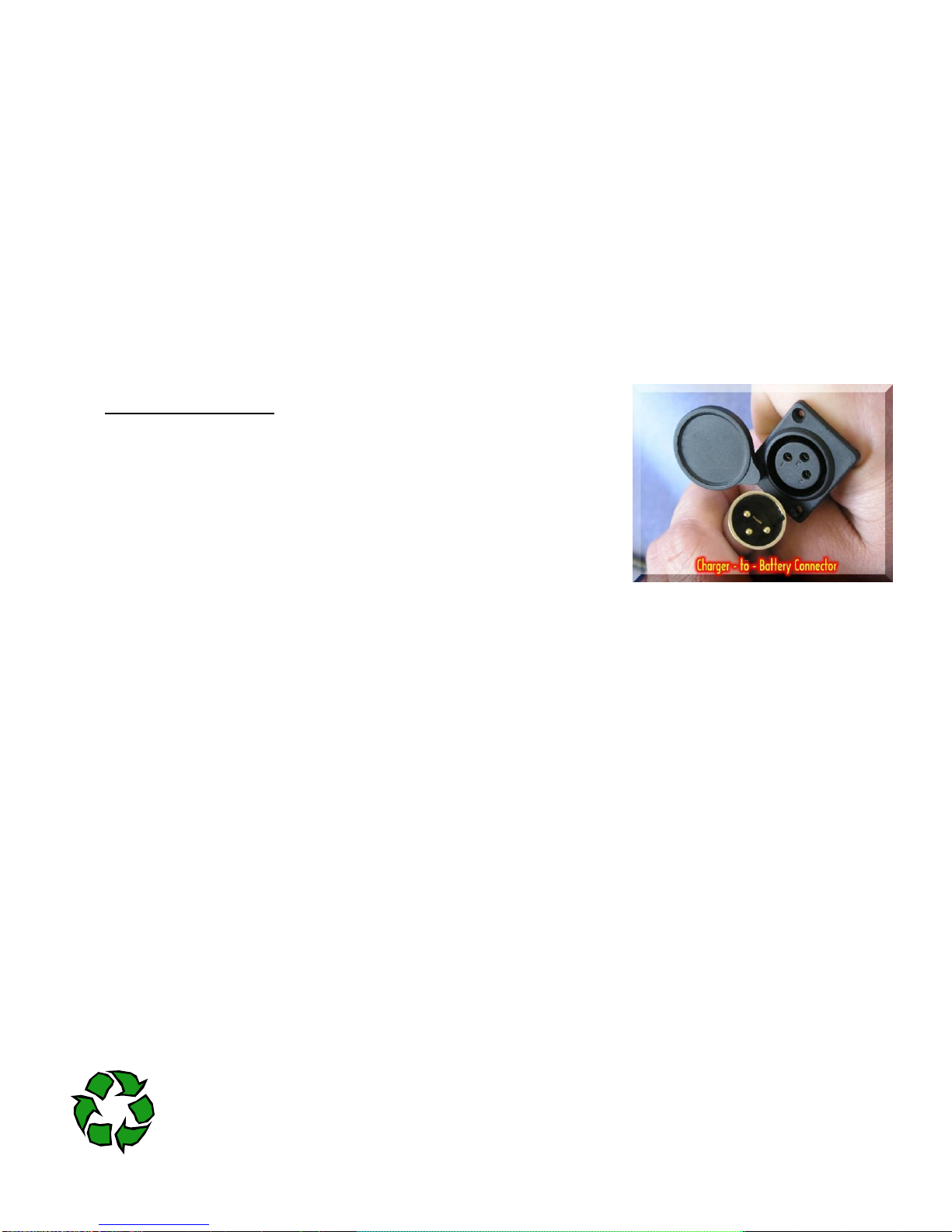
Charging the Battery
Charge the battery using the battery pack provided by PowerQuick
Concepts, Inc with your PowerQuick Ascender. (Figure 1)
Insert the 3-pin plug on the battery charger into the matching receptacle
on the top of the battery. (Figure 2)
Plug the charger into the electrical outlet. The charger is compatible with
110 and 230VAC. Locate the switch on the end of the charger and, using
a ball point pin, move it to the correct setting.
An LED on the end of the charger indicated red for power on, yellow for
charging and green for full charge. When the indicator turns green,
disconnect the battery, and then remove the battery from the charger.
4.2.Battery Warranty
PowerQuick Concepts, Inc. Battery Packs are warranted against defects in workmanship, material and construction for a
period of one (1) year from date of shipment. The warranty period is void if the purchaser does not adhere to storage
instructions specifying both storage time and temperature (a charged battery may be stored up to 1 year at room temperature
68° F), are modified, subjected to abuse, physically damaged when allowed to discharge below 25 VDC, or charged with a
charging device not approved by PowerQuick Concepts, Inc.
If the battery pack is found to be defective it will be replaced at no charge. If, however, it is defective due to misuse as
outlined in this warranty the customer will be so advised and replacement will NOT be issued. The liability of PowerQuick
Concepts, Inc. under the warranty is limited to a replacement of the defective battery pack subject to the conditions as
outlined in this paragraph. The warranty is the exclusive remedy.
THERE ARE NO OTHER WARRANTIES EITHER EXPRESSED OR IMPLIED INCLUDING THOSE OF
MERCHANTABILITY AND FITNESS FOR A PARTICULAR PURPOSE AND SUCH WARRANTY IS LIMITED TO THE
EXPRESS WARRANTY PERIOD. LIABILITY FOR CONSEQUENTIAL OR INCIDENTAL DAMAGES UNDER ANY AND ALL
WARRANTIES ARE EXCLUDED TO THE EXTENT EXCLUSION IS PERMITTED BY LAW. THE SOLE REMEDIES FOR
BREACH OF ANY AND ALL GUARANTEES OR WARRANTIES AND THE SOLE REMEDIES FOR POWERQUICK
CONCEPTS, INC.PRODUCT’S LIABILITY OF ANY KIND WITH RESPECT TO THE PRODUCTS FURNISHED UNDER
THIS AGREEMENT, OR PURSUANT TO THIS AGREEMEN T, SHALL BE LIMITED TO THE REMEDIES PROVIDED IN
THE PRECEDING APPLICABLE PARAGRAPHS HEREOF. IN NO EVENT SHALL POWERQUICK CONCEPTS,
INC.PRODUCT’S LIABILITY FOR DAMAGES WITH RESPECT TO ANY OF THE PRODUCTS FURNISHED EXCEED THE
CHARGES PREVIOUSLY PAID BY CUSTOMER FOR SUCH PRODUCTS.
CUSTOMER AGREES THAT POWERQUICK CONCEPTS, INC.PRODUCT’S SHALL NOT BE LIABLE FOR ANY SPECIAL,
INCIDENTAL, INDIRECT OR CONSEQUENTIAL DAMAGES OR LOSS OF USE, REVENUE OR PROFIT, EVEN IF
POWERQUICK CONCEPTS, INC.PRODUCT’S SHALL HAVE BEEN ADVISED OF THE POSSIBILITY OF SUCH
POTENTIAL LOSS OR DAMAGE.
4.3.Battery Disposal
In accordance with the Environmental Protection Agency Rechargeable Battery Management Act, 42 U.S.C 14301-
14336 (“Battery Act”) rechargeable batteries must be disposed of by recycling. To locate a recycling facility in your
Figure 2

PowerQuick Powered Ascender (6) PQ500-1 1-Sep-15
area go to http://www.rbrc.org/consumer/uslocate.html or call the Rechargeable Battery Recycling Corporation, a nonprofit
organization which manages the Charge up to Recycle! Program at 1-800-8-BATTERY.
5. Certification/Maintenance Requirements
This Ascender must undergo maintenance, inspection and certification following every 3.4 miles/6K (20,000
rotations as measured by the odometer located on the side of the Ascender) of use, whichever comes first. The
certification requirements of each ascender are printed on the Maintenance Inspection Log located inside the back
cover of this Manual.
The ascender must also be recertified any time it is subjected to a drop from a distance of more than 5 feet. Or if it is
subjected to an on-line drop of more than 1 foot.
Maintain diligent maintenance inspection logs in the space provided on the inside back cover of this booklet. Your
sales person has recorded the beginning odometer reading in the inspection log and indicated the reading when the
next maintenance inspection is due. This reading will be tracked and updated each time your unit is serviced.
Additionally, a permanent record of all service for your unit will be maintained in the PowerQuick Concepts, Inc.
maintenance database.
Service must be performed only by a PowerQuick Concepts, Inc. Certified Maintenance Facility. Service or
maintenance performed by unqualified repair personnel could result in injury or death and will void the warranty.
Failure to follow maintenance and certification requirements voids all warranties, written or implied.
PowerQuick Concepts, Inc. our partners and subsidiaries are not responsible for damage or injuries that result from
failure to maintain the ascender in accordance with these instructions.
6. Certified Maintenance Facilities or Principle Points of Contact
USA
PowerQuick Concepts, Inc
3000-B Conestoga Drive,
Carson City, NV 89706
(775)882-8100
http://wwwpowerquickinc.com/
email CustomerService@powerquickinc.com
United Kingdom (Point of Contact)
PowerQuick UK
Park House
158-160 Arthur Road
London SW19 8AQ United Kingdom
+44 20 8879 3541
e-mail: richard.brooke@uko2.co.uk
Australia and Pacific Region of Southeast Asia
Vertical Innovations International Pty Ltd
Fact 4, 4-6 Tengah Crescent,
Mona Vale NSW, 2103 Australia,
PO Box 135 Mono Vale NSW 1660
1300 788 844
Office (02) 9979 2582
Mobile 0427 800 028
(02) 9979 6505
www.vertical.com.au
e-mail: info@vertical.com.au
The Netherlands
Heightinfra Ltd.
PO Box 125
5490 AC Sint-Oedenrode
The Netherlands
+31-(0)6 - 22 52 01
Email: r.stumpf@heightinfra.com
7. Definitions
Building maintenance means operations such as window cleaning, caulking, metal polishing, reglazing, and general maintenance on building
surfaces.
Control means a mechanism used to regulate or guide the operation of the equipment.
Davit means a device, used singly or in pairs, for suspending a powered platform from work, storage and rigging locations on the building being
serviced. Unlike outriggers, a davit reacts its operating load into a single roof socket or carriage attachment.
Confined or enclosed space means any space having a limited means of egress, which is subject to the accumulation of toxic or flammable
contaminants or has an oxygen deficient atmosphere. Confined or enclosed spaces include, but are not limited to, storage tanks, process vessels,
bins, boilers, ventilation or exhaust ducts, sewers, underground utility vaults, tunnels, pipelines, and open top spaces more than 4 feet in depth
such as pits, tubs, vaults, and vessels.
Lifeline means a component consisting of a flexible line for connection to an anchorage at one end to hang vertically (vertical lifeline), or for
connection to anchorages at both ends to stretch horizontally (horizontal lifeline), and which serves as a means for connecting other components
of a personal fall arrest system to the anchorage.
Live load means the total static weight of workers, tools, parts. and supplies that the equipment is designed to support.

PowerQuick Powered Ascender (7) PQ500-1 1-Sep-15
Minimal risk is defined as “the probability and magnitude of harm or discomfort anticipated in the research are not greater in and of themselves
than those ordinarily encountered in daily life or during the performance of routine physical and psychological examinations or tests” in 32 CFR
219.102(i). The overall risk level is “Less Than Minimal Risk.” This is based in accordance with this definition and regulation on the results of
component testing as discussed in Section 3, inherent safety redundancies in the design, as well the fact that the ascender will not be used in
testing, demonstration or actual use without the use of a secondary fall arrest system.
Rated working load means the combined static weight of men, materials, and suspended or supported equipment.
Registered professional engineer means a person who has been duly and currently registered and licensed by an authority within the United
States or its territories to practice the profession of engineering.
Prime mover means the source of mechanical power for a machine.
Rated load means the manufacturer's recommended maximum load.
Rated strength means the strength of wire rope, as designated by its manufacturer or vendor, based on standard testing procedures or
acceptable engineering design practices.
Rated working load means the combined static weight of men, materials, and suspended or supported equipment.
Roof powered platform means a working platform where the hoist(s) used to raise or lower the platform is located on the roof.
Roof rigged davit means a davit used to raise the suspended working platform above the building face being serviced. This type of davit can also
be used to raise a suspended working platform, which has been ground-rigged.
Rope means the equipment used to suspend a component of an equipment installation.
Secondary brake means a brake designed to arrest the descent of the suspended or supported equipment in the event of an overspeed
condition.
Tie-in guides mean the portion of a building that provides continuous positive engagement between the building and a suspended or supported
unit during its vertical travel on the face of the building.

PowerQuick Powered Ascender (8) PQ500-1 1-Sep-15
Figure 4
8. Use Instructions
The PowerQuick Personal Ascender is easy to use and operate. The photos below show the major components of the PQ
500.
Note: This configuration is slightly changed in that the tension arm uses an improved rope locking mechanism and lower
rope guide. The loading of the rope is unchanged. Also, the location of the emergency OFF button has been changed to the
top of the handle.
Figure 3

PowerQuick Powered Ascender (9) PQ500-1 1-Sep-15
8.1. Loading Instructions
1. Make sure the unit is free of debris or dirt –particularly around the
capstan (10), tension arm (6) and up-rope guide (13).
2. Open the capstan cover by turning the latch on the outside of the
cover (Figure 4).
3. Place your thumb on the up-rope guide latch (12). Push in and up to
open the guide (13). (Illustrated in figure 5)
4. Place the rope in the up-rope guide. Close the latch and push down
making sure it is firmly secure.
5. Load the rope as shown in figure 6. Make sure the first wrap of the
rope is between the capstan (10) and the capstan and the tension
arm (6). Wrap the rope around the inside V notch of the capstan and
around the outside of the capstan idler (11).
6. Pull the rope into position for a second wrap.
7. Make a second wrap around the outside capstan V grove,
8. Guide the rope through the down-rope guide (9).
9. Tug on the rope to make sure it is seated in the capstan.
10. Close and latch the cover. THE ASCENDER WILL NOT OPERATE
UNLESS THE COVER IS CLOSED AND SECURELY LATCHED. If
the cover is not closed the Red power light will blink. Recheck the
cover.
11. When the rope is properly loaded and the cover closed, turn the unit on. When the power up light is green, conduct a quick
operational check on the PQ 500. With no load, place forward/reverse lever in UP direction and pull trigger. The PQ 500 should
start to climb the rope. If it does not, pull snuggly on the down rope to seat the rope on the capstan. Once the rope is seated, it
will remain seated. Place the forward/reverse lever in the DOWN direction and pull the trigger, PQ 500 will descend. You are now
ready to climb.
12. Tying a weight of 5
to 10 pounds to the
bottom of the
climbing rope will
provide adequate
downrope tension
to prevent bunching
of the rope while in
use.
Figure 6
Figure 5

PowerQuick Powered Ascender (10) PQ500-1 1-Sep-15
8.2. Connecting the Power Supply
BATTERY CABLE CONNECTION CAN RESULT IN
ARCING. DO NOT CONNECT OR DISCONNECT
BATTERY IN A POTENTIALLY EXPLOSIVE
ENVIRONNENT. MOVE TO A SAFE AREA CHANGE
BATTERIES.
1. Make sure the battery is properly charged.
2. Attach the cord to the battery. Make sure the male and
female pins are aligned by lining up the notches on the plug
ends. Push firmly and screw in the connector until it is snug.
3. Repeat connections for the PQ 500 using the same process.
4. (EP) Version -- Using an allen wrench, tighten the set
screws on the connector at both ends of the cable. SCREWS
MUST BE TIGHTENED BEFORE USE IN A POTENTIALLY
EXPLOSIVE ENVIRONMENT. Ensure use of a battery
marked EP. Attach battery outside of the hazardous
atmosphere.
5. Repeat the procedure when attaching the other end of the
cord to the ascender.
6. Using a carabineer, attach the battery to a D-ring on the side
of your climbing harness or the load attachment point at the
bottom of the ascender. DO NOT LET THE BATTERY HANG
FROM THE ASCENDER UNSUPPORTED.
7. NOTE: For the conventional version, the battery can be
connected at the work site. The process is the same as that listed above, except that there is no set screw on the
battery cable.
8.3. Connecting to the Ascender
1. Make sure the climbing rope and fall arrest system is properly anchored. (See
Section 12) We recommend the MIO Trailing Rope Grab.
2. When Using the rope grab place a small weight at the bottom of the belay rope.
This allows the fall arrest to rise as you climb without kinking on the rope.
3. Attach the ascender to
the D-ring at the waist of
the climbing harness
using a carabineer
attached to the
attachment point at the
bottom of the ascender. PowerQuick Concepts, Inc.
recommends use of a full body harness.
4. Attach the fall arrest device to the D-ring on the back of
your climbing harness.
5. Let your weight down on the ascender firmly.
8.4. About the Power Control
1. Press and release the Power-On Button. This begins the
initialization cycle for the electronics.
2. The red indicator above the Power-On Button will light.
3. Rope cover ajar—red indicator blinks twice. Closing cover will restart power up.
4. In rare conditions associated with extremely long climbs the motor may potentially overheat. If this occurs the red
indicator on the on button blinks once. The unit will automatically shut off. Wait 15 minutes for unit to cool then turn
the power back on by pressing the Power-On Button.
5. In the event of a low battery voltage, the unit will shut down automatically. It will also start the power up sequence
by itself. If this happens, there will not be adequate charge in the battery to allow the ascender to climb, but it will be
able to descend.
Figure 8 :Rope Grab
Figure
7
Figure 9: Power Controls

PowerQuick Powered Ascender (11) PQ500-1 1-Sep-15
8.5. Climbing with the ascender
The PowerQuick 500-1Ascender features a trigger release, a two-position trigger and an up/down lever.
1. Move the up/down lever to the correct position by pulling the release pin and moving the lever. (Figure 10)
2. Place your hand inside the handle with you palm against the trigger release. The default position with the trigger
release open is the brake. Any time the trigger is released the brake is engaged.
3. Press firmly on the trigger release with the palm of your hand.
4. Squeeze firmly on the trigger. You will go up or down depending on the position of the up/down lever.
5. To stop simply release the trigger and the ascender will hold on the rope for working.
6. If the battery begins to loose power during ascent, simply switch to descend. The unit uses so little power on
descent that it is virtually impossible to be “stranded on the rope from loss of battery charge.
The unit can be stopped at any location on the rope and the direction changed
.
8.6. Remote Control
The PowerQuick ascender is equipped with a wireless
remote control. The Transmitter and receive is certified for
FCC Part 15 and Industry Canada RSP-100 compliance.
The 433.92MHz version has also been tested for CE
compliance for use in the European Union.
1. Depending on the configuration, some units
may have an external antenna while others
may have an internal antenna. If your unit
has an external antenna fixture attach the
antenna as shown in Figure 14.
2. The Remote Control transmitter is keyed to a
specific ascender. They are
numbered as pairs. Make sure
the number printed on the
Remote Control matches the
Serial number on the ascender.
Only the appropriate ascender
can be used with the Remote. If a
remote control receiver is
damaged or lost We can provide
a replacement and instructions to
set the remote. This requires
removing the electronics package
so should be conducted by an
authorized service center unless
the user is experienced in
working with electronics.
3. The transmitter has five buttons—
ON/OFF, UP/ DOWN and CMD
(Command). ON turns on the
remote control allowing it to
communicate with the ascender.
Figure 10: Up/Down Lever
Figure 11: Trigger
Figure12: Attaching the antenna
Figure 13: Remote
Control off/on
Figure 14: Remote transmitter
Figure 15: Battery
location

PowerQuick Powered Ascender (12) PQ500-1 1-Sep-15
Figure 16: UP/DN Lever
OFF suspends communication. To go UP or DOWN, first Press the CMD button and the desired direction button
within 5 seconds. This is a safety action that prevents accidental powering of the ascender if the action buttons on
the remote transmitter are accidently engaged such as can happen if someone puts the remote in their pocket
4. The remote will override local, manual commands. That is, when the Remote Control is commanded, the Local
Control is disabled.
5. The effective range of the Remote is approximately 750 feet; however, the range may be reduced for some
conditions such as metal shielding.
8.7. Battery
The transmitter utilizes a standard CR2032 lithium button cell. In normal use, it will provide 1 to 2 years of operation. Access for
replacement is accomplished by gently prying apart the two halves of the Keyfob at the seam (fingernails or a coin will do). Once
the unit is open, remove the battery by sliding it out from beneath the retainer. There may be the risk of explosion if the battery is
replaced by the wrong type. Replace it with the same type of battery while observing the polarity shown in the adjacent figure.
1. WHEN USING THE REMOTE TO CONTROL THE ASCENDER, ALWAYS MAINTAIN VISIBLE
CONTRACT WITH THE POWER QUICK.
2. Turn off cell phones as interference may occur with some brands of phones.
8.8.Pendant Remote (Tower Version) and Bite switch and bite Switch (optional)
The PQ 500-TR is equipped with a hard-wired pendant remote. There
may also be an optional bite switch to allow for complete hands-free
operation. The pendant provides all of the machine controls in a
separate, hardwired remote control unit. It allows the operator to be
suspended below the ascender as in a Boson’s chair. This is
particularly handy when using in overhead configurations and in some
communications towers or large steel buildings where excessive
microwave or other electrical signals interfere with the operation of
the wireless remote.
Operations:
1. Prepare the PowerQuick 500 for pendant operation by
setting the UP/DN lever to the UP position.
INSTRUCTION TO THE USER
This device complies with Part 15 of the FCC Rules.
Operation of this device is subject to the following two conditions:
(1) This device may not cause harmful interference, and
(2) this device must accept any interference received, including interference that may cause undesired operation.
This equipment has been tested and found to comply with the limits for a Class B digital device, pursuant to Part 15 of the FCC Rules. These limits are
designed to provide reasonable protection against harmful interference in a residential installation. This equipment generates, uses and can radiate
radio frequency energy and, if not installed and used in accordance with the instructions, may cause harmful interference to radio communications.
However, there is no guarantee that interference will not occur in a particular installation. If this equipment does cause harmful interference to radio or
television reception, which can be determined by turning the equipment off and on, the user is encouraged to try to correct the interference by one or
more of the following measures:
Reorient or relocate the receiving antenna.
Increase the separation between the equipment and receiver.
Connect the equipment into an outlet on a circuit different from that to which the receiver is connected.
Consult the dealer or an experienced radio/TV technician for help.
This equipment has been certified to comply with the limits for a Class B computing device, pursuant to FCC Rules. In order to maintain compliance with
FCC regulations, shielded cables must be used with this equipment. Operation with non-approved equipment or unshielded cables is likely to result in
interference to radio and TV reception. The user is cautioned that changes and modifications made to the equipment without the approval of
manufacturer could void the user’s authority to operate this equipment.

PowerQuick Powered Ascender (13) PQ500-1 1-Sep-15
Figure 17: Pendant with Bite Switch
Emergency Off
UP LED
DN LED
Selector
Switch
ON
OFF
Trigger
Bite Switch
Bite Switch
Connector
2. Attach the pendant remote using the connector on the PQ 500 gear box.
3. Pendant Control Functions:
a. ON—red button on the left side of pendant.
b. OFF—black button on the right side of pendant.
c. E-OFF—red button on top of front face of pendant.
d. Red LED—Power ON light on right.
e. Green LED—Machine READY light on left.
f. UP—causes machine to ascend.
g. DN—cause machine to descend.
4. General operating with Pendant:
a. DO NOT put excessive force on the pendant during
use. It is tested to 70 pounds of pull force, but it is not
a handle.
b. Always check out the machine function while still in a
safe location to insure proper function.
c. Power the PQ 500 up by pressing the ON button.
This will result in the Red LED lighting for 10 seconds,
followed by the Red LED going out with the Green
LED lighting. You can now run the machine with the
UP and DN buttons as appropriate.
d. Ensure that the E-OFF function is operable by powering PQ 500 up, then pressing the E-OFF button. All LEDs
should go out within one second.
e. Restart the machine by pressing the OFF button followed by the ON button.
f. The Pendant remote can now be used while suspended below the PQ 500.
5. Optional Bite Switch Function with a Pendant:
a. Ensure manual switch on the ascender is in the “UP” position.
b. Connect pendant to ascender, making sure the connector is tight.
c. With the ascender turned “OFF”, plug in the bite switch to the back of the pendant (see Figure 17).
d. Ensure the selector switch is in the proper position, as this will determine the direction of travel.
e. Press the “ON” button on the pendant.
f. Use the bite switch to approximate the trigger on the pendant. Use approximately 10 lbs of force to activate the
bite switch.
6. When operated in this configuration a lanyard must be attached to the manual brake release lever. (The Manual Brake
Release Function is described in detail in section 8.8.)
This allows operation of the manual brake by simply reaching above your head and tugging on the lanyard.
To rig the configuration:
a. Attach a strong cord (4 mm prussic cord) or lanyard to the ring on the manual brake lever.
b. Route the cord through the carabineer at the base of the machine so that it hangs down approximately 1 foot,
within easy reach of the operator. In this way, pulling down on the cord will pull the brake lever towards the
base plate of the PQ 500 releasing the manual brake.
For more information on rigging see section
8.9.Brake function
1. Automatic brake—the automatic brake allows for either local or remote control. That is, the control is only to tell the
motor to go forward or reverse. No command results in stop.
2. The brake on the PQ-500 is automatically applied as the motor function. That is, if the motor is commanded to “up” it
first releases the brake, then powers the unit up.
3. The brake is a multi-plate device with three rotors and four stators. The rotors are stainless steel while the stators are
oilite bronze.
4. A pressure plate is spring-loaded and presses on the stack of rotors and stators.
5. A throw out device is actuated by torque from the motor.

PowerQuick Powered Ascender (14) PQ500-1 1-Sep-15
8.10. Manual Brake Release
The PowerQuick 500 incorporates a Manual Brake release, which can be used for finite
positioning or for emergency release in the case of loss of power.
1. Depress the brake release lever by pinching the lever with the thumb.
It may be helpful to use the underside of the metal housing press
against. CAUTION THE HOUSING MAY BECOME HOT DURING
USE.
2. Do not allow the load to build up considerable speed. It is best to start and stop the
load often -- for example, every foot or so of drop. The operator may opt to lower
lighter loads, say 200 pounds, somewhat faster.
3. To begin descent, press the lever on the end of the ascender as shown in the photo
at right. Use only brief depressions. When your thumb is removed from the lever
the PowerQuick automatically stops on the rope
4. Use caution when becoming accustomed to this feature as the rate of descent is
more rapid than a normal powered descent.
5. The brake will heat up during a long descent. It should be allowed to cool
periodically, particularly if the load is near the maximum rated load. We
recommend a 1 to 2 second rest every 10 feet and a 15 to 30 second rest every
200 feet regardless of load.
8.11. Attaching the Load and Checking Lift Capacity
The unique PowerQuick load limiter feature prevents accidental overloading of the unit, increasing user safety. It will disengage
the rope handler if the load is excessive. As shown in figure 3, it is integral to the load attachment point. The load limiter function
is to clamp the rope to the capstan, until the limit load is reached. While the PQ 500 is rated for use with 500 lbs, the limit load is
set at about 900 pounds as a safety factor. The load limiter will release the tension on the rope in dynamic loading conditions.
For example if there is slack in the rope above the load that releases when the load is lifted, the load limiter will keep the shock
loads to less than 2,500 pounds in the event the load is subject to a .6 meter drop.
1. The load is always attached to the load limiter loop. Note: Do not attach the load to any other part of the ascender.
2. For proper function of the ascender, DO NOT USE AT MORE THAN THE RATED LOAD. Estimate the load prior to
attaching to the ascender. The following test should be conducted; however, it does not relieve the operator of
responsibility of ensuring proper loading of this equipment. (Note: the PQ-500 is rated for 500 pounds. In order to
insure proper performance with the rated load, the unit will actually lift more than that weight. Therefore, it is imperative
that you keep the load within the recommended range.)
3. The ascender has overload protection. Check the load before lifting greater than 3 feet above floor level.
4. Clutch—A centrifugal friction clutch limits the torque from the motor. (Normal clutch operation is based on a proper
loading of the ascender and charge of the battery.) If the load is excessive and the battery voltage is low, the clutches
may slip. If this slippage continues for 2-3 seconds, they will overheat and cause the lubrication to smoke.
5. When the temperature is at freezing we recommend the ascender
be run up and down the rope a short distance five or six times to
warm the parts before using with a load.
8.11.1. Load test—(Note: this test
is performed with a fully charged battery. A
low charge on the battery will result in
stalling of the ascender clutch.)
1. The loaded ascender should be lifted approximately 2 feet off the
floor or ground level as appropriate. If the ascender does not lift
the load cleanly, it is either too heavy of the battery charge is low.
2. Bounce the load on the line. For example, release the manual
brake and let the load descend for about 1 foot, then engage the
brake. This action should induce a slight oscillation or bouncing of
the loaded ascender. (Note: This bouncing on the rope will
introduce dynamic loads that will cause the load limiter to trip if the
load is greater than 700 pounds.) If the brake fails to stop the
load, the ascender may be faulty and should be returned to the
manufacture’s qualified service center.
Figure 19: Attaching to the load limiter
Figure 18: Manual Brake
Release

PowerQuick Powered Ascender (15) PQ500-1 1-Sep-15
3. Command the ascender to climb. If there is a hesitation or inability to
climb, the load is too heavy and should be reduced by about 200
pounds.
4. The ascender is now ready to transport the load to the desired position.
5. Tying a weight of 5 to 10 pounds to the bottom of the climbing rope will
provide adequate downrope tension to prevent bunching of the rope
while in use.
8.12. Thermal Protection
1. The PQ 500 has a thermally protected motor. Thermal switch—A
thermal switch rated at 85°C is located near the motor.
2. Operation—The PQ 500 will lift the rated load 200 feet or about 60
meters of continuous climb without extensive heating if the initial
temperature is 70°F or 20°C. Colder ambient temperatures will result in
longer climbs, while higher ambient temperatures reduce the climb
distance It is recommended that for long climbs, the operator rest the
PQ 500 every 200 feet to allow the unit to remain cool.
CAUTION: This is a high-power unit. External surfaces near the
motor and gearing tends to get hot during extended operation.
The temperature will not burn the skin, however can become
uncomfortable to the touch. May consider optional heat guard.
3. If the sensor detects an over temperature condition, it will open and stop
the operation of the ascender. This function will show as a blinking red
light by the power switch. Normal operation will return when the unit
cools (about 5 minutes). This will be signified by a solid green light.
8.13. Horizontal applications
The PowerQuick can be used effectively for horizontal as well as vertical access
related to work positioning and egress.
Rigging requires the use of three ropes, one of which carries the primary weight,
a second, which is attached to the ascender, and a third which is used for the fall
arrest.
The three ropes must be rigged using approved techniques (see section 12) From
one side to the other as shown in figure 20-22.
1. The weight carrying rope (shown in blue in figure 21) must be
pulled tight from point A to point B. A pulley is attached to that rope.
2. The fall arrrest rope should be attached in the same process and
pulled tightly.
3. The work rope (shown as orange in figure 23) should be attached
snugly to the upermost height and allowed to hang loose or be
attached loosely.
4. PowerQuick is loaded on the work rope in the normal manner,
5. Using a
carabiner,
attach the loop
on the pulley
to theloop on the PowerQuick.
6. Using a separate carabiner, attach the PowerQuick to the loop
on your climbing harness.
7. Attach the fall arrest to the thirdrope.
8. Pull the trigger on the ascender to move along the lenth of the
rope.
Figure 23: Attaching the PowerQuick for
horizontal operations.
Figures 20, 21, 22: Fire Department
personnel practice horizontal rigging.
In this case the lines were anchored to
the top of the training tower and back
of the emergency response vehicle.

PowerQuick Powered Ascender (16) PQ500-1 1-Sep-15
8.14. Extended work at heights and
extremely long climbs, rescues
When working in situations where considerable time is spent at
height, or when it is important that nothing impede forward reach,
the ascender can be rigged using an overhead configurations. This
entails using a spreader bar and a bosn’s chair rigged as shown in
figure 25.
For extremely long climbs or when it is inconvenient to change
batteries during the work cycle, the ascender can be used with a
special battery connector Two batteries can attached at one time
and attached to the spreader bar.
This configuration can only be used with Tower wired remote
remote version. A lanyard is attached to the manual release lever
and threaded through the spreader bar for easy access to the
climber.
The remote version can also be used to position loads as shown in
figure 26 or in tandem applications for moving larger items. Tandem
use is not allowed in some countries for the lifting of personnel.
Check with the regulatory agencies in your country.
Figure 25: Remote operations configurations
Figure 26: Material lifting
configuration
Figure 24: Dual
ascender configuration
Figure 27: Dual Rescue Configuration
Figure 28: Tower
Configuration
Figure 29: 2-man Vertical
Rescue Configuration
This manual suits for next models
1
Table of contents