Occupancy Sensor Power Pack
Cat. No. LCA2285, LCA2287
(with HVAC relay)
Load Ratings: 20A, 2400W @ 120V, 60Hz – Incandescent, 20A, 2400VA @ 120V, 60Hz – Fluorescent
20A, 5540VA @ 277V, 60Hz – Fluorescent, 1 HP @ 120VAC – Motor Load
2 HP @ 240V, 60Hz – Motor Load, 0.5A 125V, 1A 30VDC – HVAC Relay
Cat. No. LCA2290 (with HVAC relay)
Load Ratings: 15A, 5200VA @ 347V, 60Hz – Fluorescent
0.5A 125V, 1A 30VDC – HVAC Relay
INSTALLATION INSTRUCTIONS
FEATURES
• Regulated24VDC,150mAoutputcurrent(120mAforLCA2290)
• MountsinsideFluorescentBallastcavity
• MountsinsideoroutsideJunctionBox
• TeoncoatedClassIIwiresforplenumwiring
OPERATION
Close Relay: Whentheattachedoccupancysensordetectsmotion,itwillapply+24VtotheOccupancywirecausingtherelaytoclose.ThisincludestheHVACrelayonequippedmodels.
Open Relay: Whentheattachedoccupancysensordoesnotdetectmotiontherelaywillopen.ThisincludestheHVACrelayonequippedmodels.
• LightsFlickering
- Lamphasabadconnection.
- Wiresnotsecuredrmlywithwireconnectors.
• LightsdonotturnON
- Circuitbreakerorfusehastripped.
- Lampisburnedout.
- LampNeutralconnectionisnotwired.
- Low-voltagemiswired.VerifywiringconnectionsperappropriateWiringDiagarms.
- Linevoltagemiswired.VerifywiringconnectionsperappropriateWiringDiagarms.
• LightsstayON
- Constantmotion.ToTest:Adjustsensor;removemotionsource.Ifunsatisfactory,movesensor.
• LightturnsONtoolong
- Adjustsensor.
TROUBLESHOOTING
RATINGS
Part Number HVAC Relay Power Input1Power Output2
LCA2285 No 120-277VAC,60Hz 24VDC,150mA 3.6W
LCA2287 No 120-277VAC,60Hz 24VDC,150mA 3.6W
LCA2290 Yes 347VAC,60Hz 324VDC,120mA 3.0W
1 Inputvoltagetolerance10%Frequencytolerance5%.
2 Outputvoltagetolerance15%,Outputvoltagelistedatnominal.
3 VoltagerangefortheLCA2290is19-27VDCbasedonloadandtemperatureconditions.
DESCRIPTION
Thepowerpackcontainsapowersupply,aloadswitchingrelayandonsomemodels,aHVACrelay.ThepowersupplyprovidesClassIIlow-voltagepowerforPhilipsLRM2250,
LRM2255,LRM2260,LRM2265,LRM2270,LRM2275,LRM2280OccupancySensors.Therelayinthepowerpackiscontrolledbytheoccupancysensorsconnectedviathe22
GaugeBlue"occupancy"wire.Multipleoccupancysensorscanbeconnectedtoasinglepowerpackinordertofullycoveranarea.
Thepowerpacksincludezerocrossswitchingcircuitrytominimizeinrushcurrentassociatedwithincandescentandelectronicballasts.Thisreduceswearandtearontherelay
contactsmakingthepowerpacklastlonger.
Application Notes:
1. Whenalightingloadexceedsasinglepowerpack’srating,theloadcanbesplitbetweenmultiplepowerpacks.Thelowvoltageoccupancyinput(Bluewire)andDCreturn
(Blackwires)ofthepowerpacksmustbeconnectedtogetherforallpowerpackstooperatetogetherasone.ConnecttheBlue(occupancy)wiresofallpowerpacksandsensors
together.ConnecttheBlack(return)wiresofallpowerpacksandsensorstogether.ConnecttheRed(+24VDC)wiresofthesensorstotheRedwiresofonlyonepowerpack.
NeverconnecttheRed(+24VDC)wiresoftwodifferentpowerpackstogether.
2. Whenmoresensorsarerequiredthanonepowerpackcansupply,multiplepowerpackscanbeusedtosupplypowertotheoccupancysensor,butnotswitchanyload.The
primarypowerpackisthepowerpackswitchingtheload.Thesecondarypowerpacksonlyprovidelowvoltagepowertotheoccupancysensor(s).Connectasmanysensors
totheprimarypowerpackaspossible(seecurrentcapacitysectionbelow),byconnectingtheRedwiresofthesensorstotheRedwire(+24VDC)oftheprimarypowerpack.
ConnecttheRedwires(+24VDC)oftheremainingsensorstotheRedwiresofthesecondarypowerpack.ConnecttheBlack(return)wiresofallpowerpacksandallsensors
together.ConnecttheBlue(occupancy)wireofallsensorstogethertotheBluewire(occupancy)oftheprimarypowerpack.NeverconnecttheRed(+24VDC)wiresoftwo
differentpowerpackstogether.
INSTALLATION
WARNING: TOAVOIDFIRE,SHOCK,ORDEATH;TURN OFF POWERATCIRCUITBREAKERORFUSEANDTESTTHATPOWERISOFFBEFOREWIRING!
WARNING: TOBEINSTALLEDAND/ORUSEDINACCORDANCEWITHAPPROPRIATEELECTRICALCODESANDREGULATIONS.
WARNING: IFYOUARENOTSUREABOUTANYPARTOFTHESEINSTRUCTIONS,CONSULTANELECTRICIAN.
WARNING: USETHISDEVICEWITHCOPPER OR COPPER CLAD WIRE ONLY.
WARNING: DISCONNECT POWERWHENSERVICINGFIXTUREORCHANGINGLAMPS.
TO INSTALL:
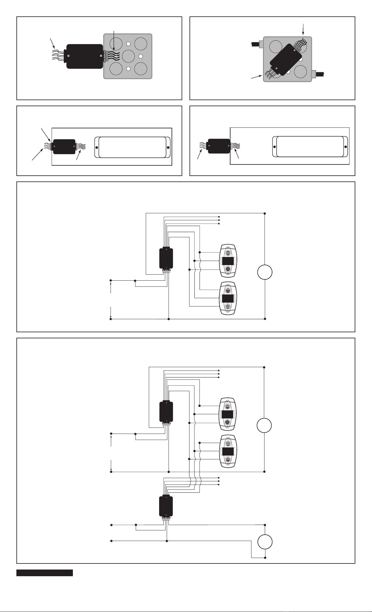
1. Mount power pack per desired application:
A. Tomountoutside4"x4"junctionboxusing2"EMTnipple,refer to Figure 1.WireperStep3Aand3B.
B. Tomountinside4"x4"junctionbox,refer Figure 2.WireperStep3Aand3B.
• Ensurethatconduit/cableentryclampislocatedincornerofjunctionbox.
• Dresswirestoprovideenoughclearancewhendeviceisinstalled.
CAUTION: Low-voltagewiresmustalsobedressedsotheyareseparatefromthehighvoltage(ClassI)conductors.Refertolocalbuildingcodesfortheappropriateinstallation
requirementsforthelow-voltagewiring.Jacketingoverthelow-voltagewiresmayberequiredtoprovideappropriateinsulationfromthehigh-voltagewiring.
C. Tomountinsideballastcavityoflightxture,refer Figure 3A.WireperStep3Aand3B.
CAUTION: Low-voltagewiresmustalsobedressedsotheyareseparatefromthehighvoltage(ClassI)conductors.Refertolocalbuildingcodesfortheappropriateinstallation
requirementsforthelow-voltagewiring.Jacketingoverthelow-voltagewiresmayberequiredtoprovideappropriateinsulationfromthehigh-voltagewiring.
D. Tomountoutsideballastcavityoflightxture,refer Figure 3.WireperStep3Aand3B.
2A. Line Voltage Wiring:Remove5/8"(1.6cm)ofinsulationfromeachcircuitconductor.Makesurethatendsofconductorsarestraight.ConnectleadwiresfromPowerPackto
LINEcircuitperappropriateWIRINGDIAGRAMasfollows:Twiststrandsofeachleadtightlyand,withcircuitconductorspushrmlyintoappropriatewireconnector.Screw
connectorsonclockwisemakingsurethatnobareconductorshowsbelowthewireconnectors.Secureeachconnectorwithelectricaltape.
2B. Class II and HVAC Wiring:ConnectLow-VoltagewiresfromPowerPacktoSensorperappropriateWIRINGDIAGRAMasfollows:Twiststrandsofeachleadtightlyand,with
circuitconductors,pushrmlyintoappropriatewireconnector.Screwconnectorsonclockwisemakingsurethatnobareconductorshowsbelowthewireconnectors.Secure
eachconnectorwithelectricaltape.
3. RefertosensorInstallationInstructionsforfurtherdetails.
4. Restorepoweratcircuitbreakerorfuse.INSTALLATION IS COMPLETE.
FCC COMPLIANCE STATEMENT (LCA2285 Only)
ThisequipmenthasbeentestedandfoundtocomplywiththelimitsforaClassAdigitaldevice,
pursuanttopart15oftheFCCRules.Theselimitsaredesignedtoprovidereasonableprotection
againstharmfulinterferencewhentheequipmentisoperatedinacommercialenvironment.
Thisequipmentgenerates,uses,andcanradiateradiofrequencyenergyand,ifnotinstalled
andusedinaccordancewiththeinstructionmanual,maycauseharmfulinterferencetoradio
communications.Operationofthisequipmentinaresidentialareaislikelytocauseharmful
interferenceinwhichcasetheuserwillberequiredtocorrecttheinterferenceathisownexpense.
LOW-VOLTAGE CURRENT CAPACITY
Total Number of
Sensor ≤150mA
Total Number of
Sensor ≤120mA
For LCA2287
For LCA2290
WIRE DESIGNATIONS
Signal Name Color Gauge
Line Voltage Wires
Line120/277V Black 18AWG
Line347V
Neutral White 18AWG
Load Blue 14AWG
Load Blue 14AWG
Class II Wires
Power(24VDC) Red 22AWG
Return Black 22AWG
Occupancy Blue 22AWG
HVAC Wires
HVACCommon Green 22AWG
HVACNO(NormallyOpen) Brown/White 22AWG
HVACNC(NormallyClosed) Brown 22AWG
Allwiresratedat105°C,600Vinsulation.
ClassIIwiresareTeoncoated,forplenumapplications.
HVACwiringisClassIandClassIIrated.