2
Troubleshooting and Repair for Series 440 Mixing Valves n
What to look for if:
• The maximum temperature cannot be obtained...
a. Lime deposits may have accumulated in the hot water pipes,
restricting the hot water supply.
b. The hot water supply temperature may be too low.
c. The knob rotation setting may be too low. Remove knobs and
stainless box assembly, then readjust the high temperature
limit stop. (Refer to maximum temperature setting section).
• Flow of water is less than desired…
a. The upstream supply valves may not be fully open.
b. The inlet supply pressure(s) may be low.
c. Lime deposits may have accumulated in cartridge, restricting
water flow. Replace cartridge kit.
d. The fixture head may be clogged. Remove and clean.
e. The checkstops may be clogged. Clean checkstops.
• The valve opens with hot water ow rather than cold water
ow...
a. The inlet water supplies are connected to the wrong ports.
Remove the valve and reinstall.
• The tempered water is too cold, although motor has been
replaced, 0R the hot water temperature is below 115°F.
a. Raise the temperature of the hot water supply.
• Flow of water is completely shut off...
a. The upstream supply valves may be completely closed.
b. The hot or cold water supply pressure may have failed. The
Hydroguard 420 valve is designed to close down upon cold
water failure.
c. The checkstops may be closed. Access the checkstops and
open by turning the adjustment screw fully counterclockwise.
Temperature Setting for Series 440 Mixing Valves n
Test the System
1. Verify that the valve is in the OFF position (fully clock-wise posi-
tion).
2. Turn on water supply and then rotate the valve knob (warmer,
cooler) counterclockwise. Water should come through the fixture
head.
Any repair or modification of the valve may affect the high temper-
ature setting. The maximum temperature setting must be checked
by the installer before use.
3. Remove the knobs, stainless steel box assembly and both
splined stops.
4. Re-insert the knob back on the (warmer, cooler) valve stem and
adjust the valve to the desired maximum outlet temperature.
Install the splined limit stop with its tab against the bottom of the
bonnet stop.
5. Re-assemble the stainless steel box assembly and the knobs.
WARNING
!
SERIES 440
FOTOPANEL
440-1000
Maximum Temperature Setting/Knob Rotation Stop
The knob rotation setting must be adjusted to limit the
distance the user can rotate the handle towards the full hot
water position.
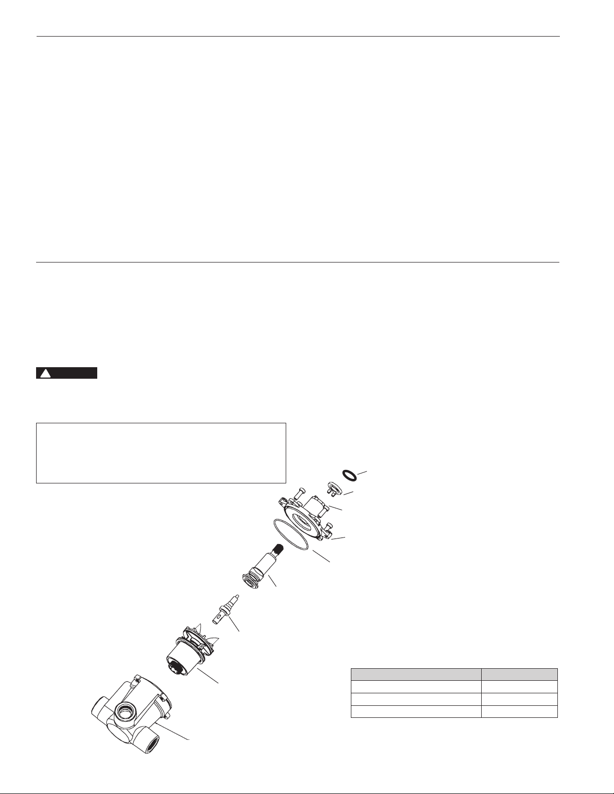
Replacement Parts Kit n
Description Repair Kit
Bonnet and Stem Assembly 420 454
Wax Element 420 453
Cartridge Assembly 420 452C
CARTRIDGE
ASSEMBLY
EXISTING VALVE
BODY
WAX
ELEMENT
STEM
"O" RING
BONNET
ASSEMBLY
BONNET SCREWS (4)
SPLINEDTEMPERATURE
LIMIT STOP ASSEMBLY
"O" RING


