manuals.online logo
Brands
  1. Home
  2. •
  3. Brands
  4. •
  5. Powers
  6. •
  7. Plumbing Product
  8. •
  9. Powers HydroGuard T/P e700 Series Owner's manual

Powers HydroGuard T/P e700 Series Owner's manual

The Series e700 HydroGuard T/P automatically mixes
hot and cold water to deliver blended water within a
specified range. Using an advanced thermal actuator,
the Series e700 quickly compensates for temperature
fluctuations induced by water temperature and pres-
sure changes. In the event of cold water failure, the
thermostatic motor virtually shuts off the flow of hot
water. HydroGuard T/P meets the most stringest per-
formance criteria for temperature and pressure
changes, defined by ASSE 1016 (Type T/P).
Featuring heavy, cast-brass construction and an
adjustable brass to brass high limit temperature stop,
self-contained cartridge, corrosion resistant internal
component, integral checks, and back to back shal-
low wall installation capability. All parts of the e700
Series valve are accessible from the front of the valve.
All Series e700 valves open in the cold water position
to ensure maximum bather safety and comfort.
The accuracy, reliability and water economy of the
Series e700 HydroGuard T/P make it preferable for
TECHNICAL INSTRUCTIONS
DESCRIPTION
SPECIFICATIONS
Valve Construction: Combination mixing valve, with heavy cast bronze body and brass stem. Concealed adjustable
high temperature limit stop. Available with ADA-compliant ABS or metal lever handle.
Connections . . . . . . . . . . . . . . . . . . . . . . . . . . . . . . . . . . . . . . . . . . . . . . . . . . . . . . . . . . . . . . . . . . 1/2” Sweat Inlet/Outlet
Capacity . . . . . . . . . . . . . . . . . . . . . . . . . . . . . . . . . . . . . . . . . . . . . . . . . . . . . . . . . . . . . . . 4 gpm @ 45 psi
ΔP 50/50
mix
Maximum Hot Water Supply Temperature . . . . . . . . . . . . . . . . . . . . . . . . . . . . . . . . . . . . . . . . . . . . . . 190°F(88°C)
Minimum Hot Water Supply Temperature (Approach Temperature) . . . . . . . . . . . 10°F (5.5°C) above set point
Maximum Operating Pressure . . . . . . . . . . . . . . . . . . . . . . . . . . . . . . . . . . . . . . . . . . . . . . . . . . . . . . 125 psig (862 kPa)
Temperature Ranges (for +/- 3°F performance). . . . . . . . . . . . . . . . . . . ASSE 1016 Type T/P: 90 - 110°F (32 - 43°C)
. . . . . . . . . . . . . . . . . . . . . . . . . . . . . . . . . . . . . . . . . . . . . . . . . . . . . . . . . . . . . ASSE 1016 Type T: 80 - 120°F (27 - 49°C)
High Temperature Limit Stop. . . . . . . . . . . . . . . . . . . . . . . . . . . . . . . . . . . . . . Adjustable (factory set at 110°F [43°C])
Maximum Static Pressure . . . . . . . . . . . . . . . . . . . . . . . . . . . . . . . . . . . . . . . . . . . . . . . . . . . . . . . . . . 125 psig (862kPa)
Minimum Flow . . . . . . . . . . . . . . . . . . . . . . . . . . . . . . . . . . . . . . . . . . . . . . . . . . . . . . . . . . . . . . . . . . 0.5 gpm (1.89 L/min)
Certified . . . . . . . . . . . . . . . . . . . . . . . . . . . . . . . . . . . . . . . . . . . . . . . . . . . . . . . . . . . . . . . . . . . . . . . . . . . . . . . . CSA B125
Listing . . . . . . . . . . . . . . . . . . . . . . . . . . . . . . . . . . . . . . . . . . . . . . . . . . . . . . . . . . . . . . . . . . . . . . . . . . . . . . . . . ASSE 1016
Shipping Weight . . . . . . . . . . . . . . . . . . . . . . . . . . . . . . . . . . . . . . . . . . . . . . . . . . . . . . . . . . . . . . . . . . . . . 3.5 lbs. (1.6 kg)
All HydroGuard T/P Series e700 combination mixing valves meet above performance specifications based on typical
operating conditions as stated in ASSE 1016 (45 psi pressure differential, hot water supply between 140°-180°F (60°-
82°C), cold water supply less than 70°F (21°C).
If your operating conditions vary from those stated in the standard, performance may vary as well. Consult your local
sales representative or a Powers factory engineer to discuss your specific application. All Powers thermostatic mixing
valves perform to the requirements of standards ASSE 1016 and CSA B125.
applications that require precise, consistent water
control: showers, baths, hospital hydrotherapy and
residential areas. All e700 valves meet the Americans
with Disabilities Act (ADA).
e710
e705 e707
Series e700
TI-e700
TI-e700 Page 2
OPERATION
Maximum Temperature Setting/Handle Rotation
Stop
The handle rotation setting must be adjusted to limit
the distance the user can rotate the handle towards
the full hot water position.
CAUTION: Any repair or modification of the valve may
affect the high temperature setting. The maximum
temperature setting must be checked by the installer
before use.
1. Remove the valve handle and sleeve.
2. Adjust the valve to the desired maximum outlet
temperature [110°F (43°C) max]. Screw on the
high temp. limit stop until it touches the stem
shoulder.
3. Turn the stem clockwise until the water stops.
Open valve to full hot position and verify maxi
mum outlet temperature setting.
4. Place sleeve "O" Ring on the bonnet shoulder.
Slide sleeve over the "O" Ring until it stops.
5. Replace handle.
Reversed Inlets
Valve is factory-set for standard inlets If reversed inlets
are required due to back-to-back installation (Cold water
supply on the left and Hot water supply on the right), follow
instructions athrough dbelow:
a. Connect cold inlet to hot port (“H”) and hot inlet to
cold port (“C”). Note: Do not turn valve upside down. If
valve is upside down, water will not flow properly
through tub spout or showerhead.
b. Turn water off with checkstops, remove bonnet and
cartridge.
c. Reinstall cartridge. “H” on the cold side of the valve
body and “C” should be on the hot side of the valve
body.
d. Reinstall bonnet with high temperature limit stop on it.
Note: Be certain that valve opens in full cold!
e. Hot and Cold inlets should be re-identified for reversed
inlets to avoid confusion during future maintenance.
Hot and cold water enter respective ports in the valve
and mix in a chamber containing an advanced thermal
actuator (refer to cutaway view). This actuator controls
the position of the plunger and temperature.
Rotating the adjustment handle repositions the plunger
in the cartridge assembly to produce the desired tem-
perature. The mixed water passes over the shut-off disc
to the outlet. If the hot or cold supply water temperature
or pressure changes, the thermal actuator will contract
or expand. This movement repositions the plunger to
maintain the desired temperature. With the adjustment
handle in full clockwise (OFF) position, the shut-off disc
closes the mixing chamber from the outlet.
A high temperature limit stop restricts the movement of
the control handle. All HydroGuard T/P e700 valves are
factory set to deliver tempered water up to 110°F [43°C]
with equal supply pressures, with hot water tempera-
ture 140°F [60°C], cold water temperature 60°F [15.6°C].
Note: The handle rotation stop must be adjusted
by the installer.
PREVENTIVE MAINTENANCE
EVERY 12 MONTHS:
Open up the checkstops and check for free movement
of the poppet. To access the checkstops, remove the
handle assembly and trim plate.
Before servicing the valve, turn off the water supply
upstream OR close the checkstops. To close the
checkstops, turn the adjustment screw fully clockwise
on each checkstop.
Remove the valve bonnet and rinse all grit and impuri-
ties from the cartridges.
Winterize valves that are used outdoors. Remove and
store the internal components and drain all water from
the valve.
NOTE: Before servicing checkstops or piping, always
turn off the upstream water supply.
TI-e700 Page 3
SAFETY GUIDELINES - ALL MODELS
1. Combination water mixing valves are control devices
which must be cleaned and maintained on a regular
basis. Powers specifies periodic maintenance at least
once a year or immediately after any changes are
made to the plumbing system. Annual cleaning is rec-
ommended, however, frequency of cleaning depends
on quality of local water conditions. Refer to the
Preventive Maintenance section for recommended
cleaning procedure.
2. The high temperature limit stop setting must be
adjusted to limit the distance the user can rotate
the handle towards the full hot water position.
3. Position the e700 valve as close as possible to outlet
fixture to avoid waste of energy and water.
Adherence to these guidelines and recommenda-
tions promotes safe product use and ensures
proper valve performance.
TROUBLESHOOTING
What to look for if:
The maximum temperature cannot be obtained...
a. Lime deposits may have accumulated in the hot water
pipes, restricting the hot water supply.
b. The hot water supply temperature may be too low.
c. The handle rotation setting may be too low. Remove
valve handle, and readjust the high temperature limit
stop (see page 2).
Flow of water is less than desired…
a. The upstream supply valves may not be fully open.
b. The inlet supply pressure(s) may be low.
c. The showerhead may be clogged. Remove and clean
the showerhead.
d. The checkstops may be clogged. Refer to Preventive
Maintenance section.
The valve opens with hot water flow rather than cold
water flow...
a. The inlet water supplies are connected to the wrong
ports or cartridge is installed improperly. See section on
“Reverse Inlets”.
The tempered water is too cold, although cartridge
has been replaced, 0R the hot water temperature is
below 115°F...
a. Raise the temperature of the hot water supply.
Flow of water is completely shut off...
a. The upstream supply valves may be completely closed.
b. The hot or cold water supply pressure may have failed.
The e700 valve is designed to close down upon cold
water supply pressure failure.
c. The checkstops may be closed. Access the checkstops
and open by turning the adjustment screw fully coun-
terclockwise.
DIMENSIONAL DATA
"
A
Part # Dim "A"
e705 6.5" (165mm)
e707 8.5" (216mm)
e710 6.5" (165mm)
TI e700 Page 4
EXPLODED VIEW and PARTS LIST - e700
9
10
REPAIR KITS
ITEM# KIT# DESCRIPTION
1 N/A Valve Body
2 220 060 Cartridge Kit
3 900 050 Checkstop Replacement Kit
4 220 054 Sleeve Kit
5 220 051 Metal Trim Plate Kit
6 220 053 ABS Trim Plate Kit
7 220 050 Metal Handle Kit
8 220 052 ABS Handle Kit
9 220 079 Dome Handle Kit
10 220 078 Metal Flat Trim Plate Kit
Description Troubleshooting Repair Kit No.
Cartridge Kit • Water leaks at valve stem and/or bonnet. 220 060
• Water leaks at valve shutoff.
• Water temperaure changes during shower.
Checkstop • Checkstop leaks or will not shut off completely 900 050
Replacement Kit
USA: Phone: 1.800.669.5430 • Fax 1.847. 229 . 0526 • www.powerscontrols.com
Canada: Phone: 1.888.208.8927 • Fax 1. 888. 882 .1979 • www.powerscontrols.ca
TI-e700 0737 EDP# 6512256 © 2007 Powers

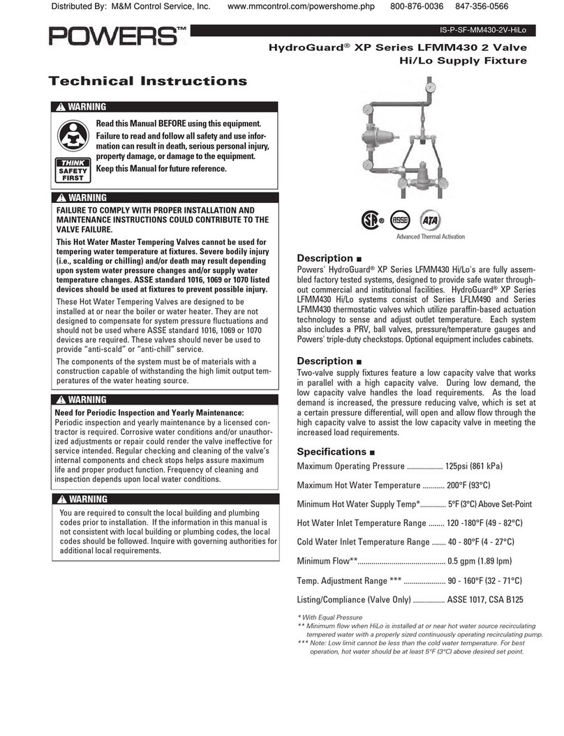
This manual suits for next models

3

Other Powers Plumbing Product manuals

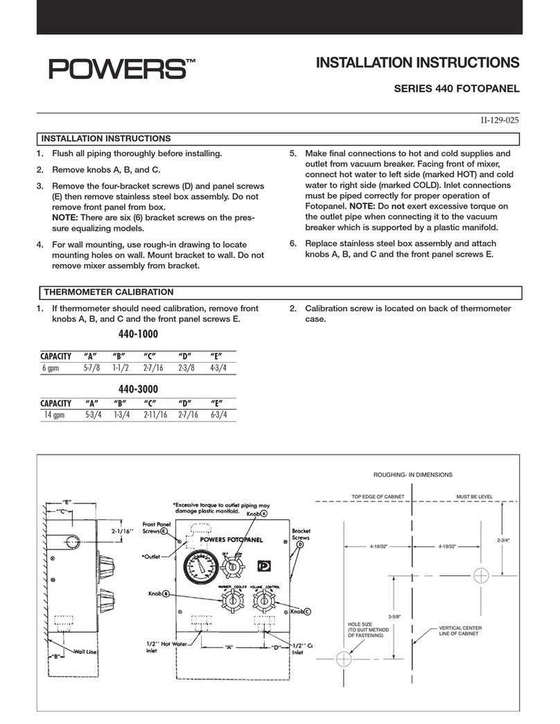
Powers 440 Series User manual

Powers

Powers 440 Series User manual

Powers HydroGuard XP LFMM430 Series Owner's manual

Powers

Powers HydroGuard XP LFMM430 Series Owner's manual

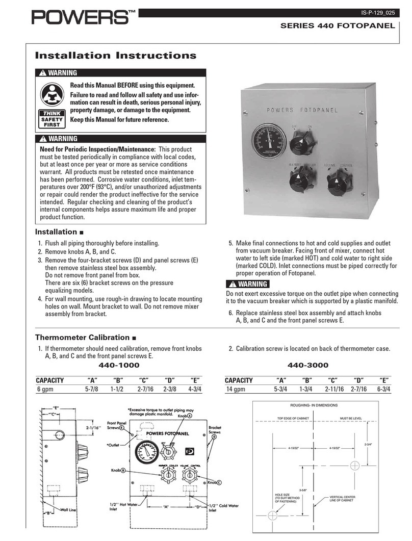
Powers 440 Series User manual

Powers

Powers 440 Series User manual

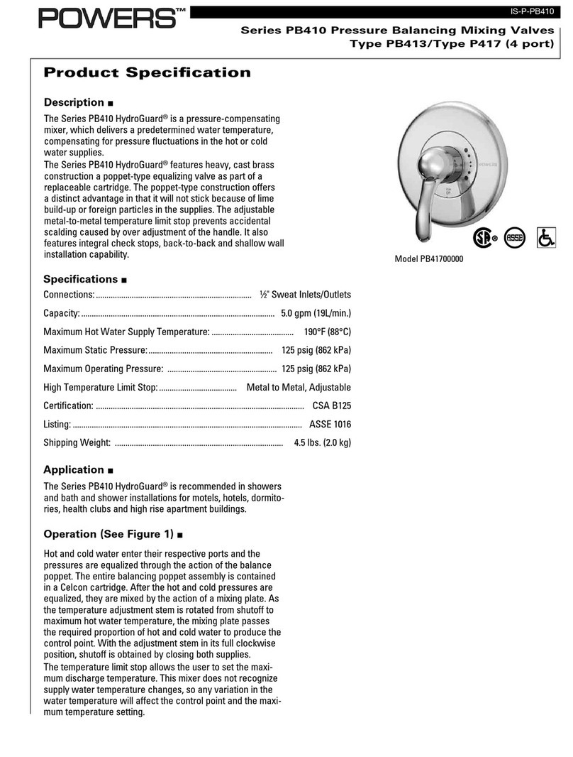
Powers Hydroguard PB410 Series User manual

Powers

Powers Hydroguard PB410 Series User manual

Popular Plumbing Product manuals by other brands

Hans Grohe Axor Citterio 39135000 Instructions for use/assembly instructions

Hans Grohe

Hans Grohe Axor Citterio 39135000 Instructions for use/assembly instructions

Spectrum Brands Pfister Jaida LF-042-JD Quick installation guide

Spectrum Brands

Spectrum Brands Pfister Jaida LF-042-JD Quick installation guide

Hans Grohe Focus 31924009 Instructions for use/assembly instructions

Hans Grohe

Hans Grohe Focus 31924009 Instructions for use/assembly instructions

American Standard 7272 installation instructions

American Standard

American Standard 7272 installation instructions

Hans Grohe Aqittura M91 240 1jet SodaSystem 76810... Instructions for use/assembly instructions

Hans Grohe

Hans Grohe Aqittura M91 240 1jet SodaSystem 76810... Instructions for use/assembly instructions

AbodeFit Zen user manual

AbodeFit

AbodeFit Zen user manual

Moen TS904 instruction sheet

Moen

Moen TS904 instruction sheet

Hansa RONDA 0342 2073 Mounting and operating instructions

Hansa

Hansa RONDA 0342 2073 Mounting and operating instructions

PEERLESS P2933LF-W Series installation instructions

PEERLESS

PEERLESS P2933LF-W Series installation instructions

Elkay LK6000 Installation & owner's manual

Elkay

Elkay LK6000 Installation & owner's manual

Sensea NEREA Assembly, Use, Maintenance Manual

Sensea

Sensea NEREA Assembly, Use, Maintenance Manual

Elkay Pacemaker PSFR3319 Specifications

Elkay

Elkay Pacemaker PSFR3319 Specifications

Sapho PS002 Instructions for use

Sapho

Sapho PS002 Instructions for use

Fortis 92211LC BRERA installation instructions

Fortis

Fortis 92211LC BRERA installation instructions

Hans Grohe AXOR Urquiola 11422 1 Series Installation instructions / warranty

Hans Grohe

Hans Grohe AXOR Urquiola 11422 1 Series Installation instructions / warranty

American Standard Copeland 7005.801 installation instructions

American Standard

American Standard Copeland 7005.801 installation instructions

IKEA ELVERDAM AA-233304-5 Assembly instructions

IKEA

IKEA ELVERDAM AA-233304-5 Assembly instructions

Swiss Madison SM-WC426 installation instructions

Swiss Madison

Swiss Madison SM-WC426 installation instructions

manuals.online logo
manuals.online logoBrands
  • About & Mission
  • Contact us
  • Privacy Policy
  • Terms and Conditions

Copyright 2025 Manuals.Online. All Rights Reserved.