manuals.online logo
Brands
  1. Home
  2. •
  3. Brands
  4. •
  5. Powers
  6. •
  7. Plumbing Product
  8. •
  9. Powers 440 Series User manual

Powers 440 Series User manual

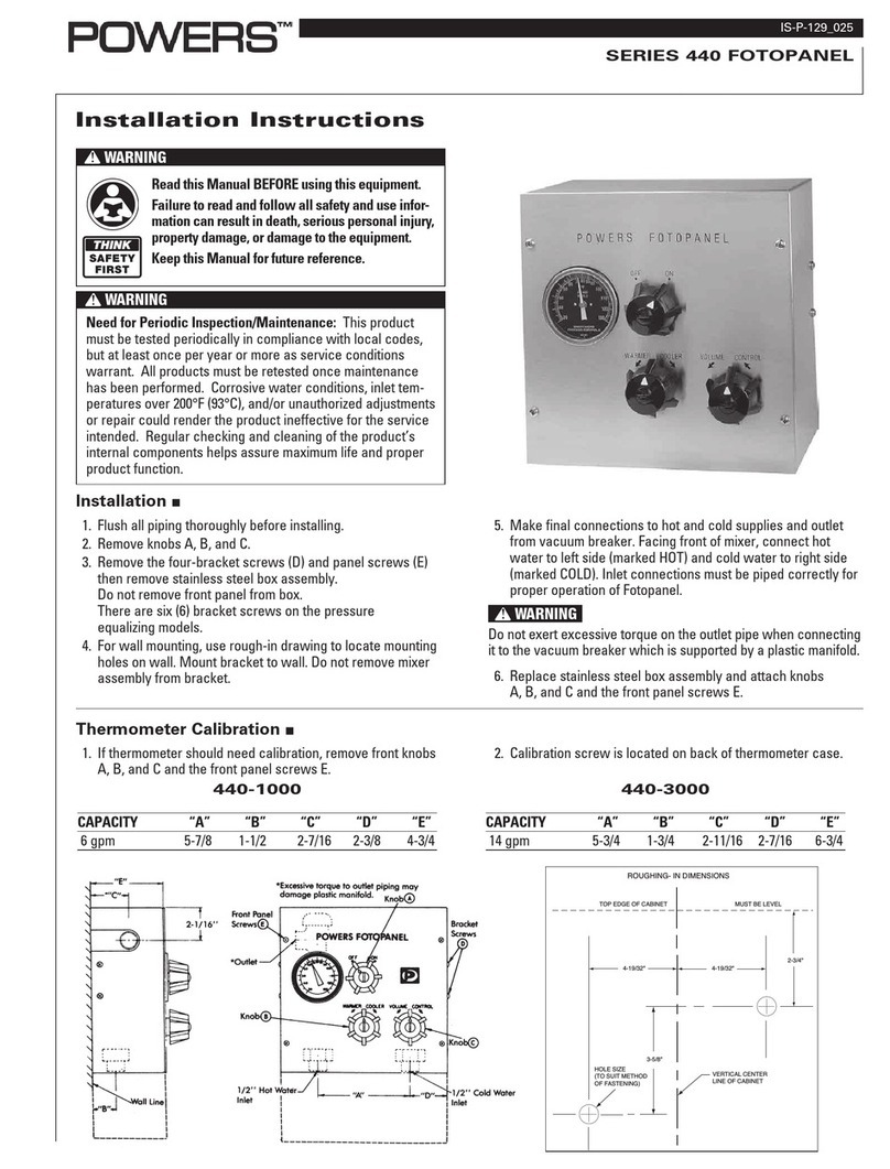
INSTALLATION INSTRUCTIONS
SERIES 440 FOTOPANEL
1. Flush all piping thoroughly before installing.
2. Remove knobs A, B, and C.
3. Remove the four-bracket screws (D) and panel screws
(E) then remove stainless steel box assembly. Do not
remove front panel from box.
NOTE: There are six (6) bracket screws on the pres-
sure equalizing models.
4. For wall mounting, use rough-in drawing to locate
mounting holes on wall. Mount bracket to wall. Do not
remove mixer assembly from bracket.
5. Make final connections to hot and cold supplies and
outlet from vacuum breaker. Facing front of mixer,
connect hot water to left side (marked HOT) and cold
water to right side (marked COLD). Inlet connections
must be piped correctly for proper operation of
Fotopanel. NOTE: Do not exert excessive torque on
the outlet pipe when connecting it to the vacuum
breaker which is supported by a plastic manifold.
6. Replace stainless steel box assembly and attach
knobs A, B, and C and the front panel screws E.
1. If thermometer should need calibration, remove front
knobs A, B, and C and the front panel screws E.
2. Calibration screw is located on back of thermometer
case.
2-3/4"
3-5/8"
4-19/32" 4-19/32"
VERTICAL CENTER
LINE OF CABINET
MUST BE LEVEL
HOLE SIZE
(TO SUIT METHOD
OF FASTENING)
TOP EDGE OF CABINET
ROUGHING- IN DIMENSIONS
440-1000
CAPACITY “A” “B” “C” “D” “E”
6 gpm 5-7/8 1-1/2 2-7/16 2-3/8 4-3/4
440-3000
CAPACITY “A” “B” “C” “D” “E”
14 gpm 5-3/4 1-3/4 2-11/16 2-7/16 6-3/4
II-129-025
INSTALLATION INSTRUCTIONS
THERMOMETER CALIBRATION
II-129-025
Page 2
SERIES 440
FOTOPANEL
440-1000
TROUBLESHOOTING AND REPAIR FOR SERIES 440 MIXING VALVES
What to look for if:
The maximum temperature cannot be obtained...
a. Lime deposits may have accumulated in the hot water
pipes, restricting the hot water supply.
b. The hot water supply temperature may be too low.
c. The knob rotation setting may be too low. Remove
knobs and stainless box assembly, then readjust the
high temperature limit stop. (Refer to maximum tem-
perature setting section).
Flow of water is less than desired…
a. The upstream supply valves may not be fully open.
b. The inlet supply pressure(s) may be low.
c. Lime deposits may have accumulated in cartridge,
restricting water flow. Replace cartridge kit.
d. The fixture head may be clogged. Remove and clean.
e. The checkstops may be clogged. Clean checkstops.
The valve opens with hot water flow rather than cold
water flow...
a. The inlet water supplies are connected to the wrong
ports. Remove the valve and reinstall.
The tempered water is too cold, although motor has been
replaced, 0R the hot water temperature is below 115°F...
a. Raise the temperature of the hot water supply.
Flow of water is completely shut off...
a. The upstream supply valves may be completely closed.
b. The hot or cold water supply pressure may have failed.
The Hydroguard 420 valve is designed to close down
upon cold water failure.
c. The checkstops may be closed. Access the checkstops
and open by turning the adjustment screw fully counter-
clockwise.
REPLACEMENT PARTS KIT
PART DESCRIPTION REPAIR KIT
BONNET AND STEM ASSEMBLY 420-454
WAX ELEMENT 420-453
CARTRIDGE ASSEMBLY 420-452C
TEMPERATURE SETTING FOR SERIES 440 MIXING VALVES
Test the System
1. Verify that the valve is in the OFF position (fully clock-
wise position).
2. Turn on water supply and then rotate the valve knob
(warmer, cooler) counter-clockwise. Water should come
through the fixture head.
Maximum Temperature Setting/Knob Rotation Stop
The knob rotation setting must be adjusted to limit the
distance the user can rotate the handle towards the full
hot water position.
CAUTION: Any repair or modification of the valve may
affect the high temperature setting. The maximum
temperature setting must be checked by the installer
before use.
3. Remove the knobs, stainless steel box assembly and
both splined stops.
4. Re-insert the knob back on the (warmer, cooler) valve
stem and adjust the valve to the desired maximum out-
let temperature. Install the splined limit stop with its tab
against the bottom of the bonnet stop.
6. Re-assemble the stainless steel box assembly and the
knobs.
II-129-025
Page 3
What to look for if:
The maximum temperature cannot be obtained...
a. Lime deposits may have accumulated in the hot water
pipes, restricting the hot water supply.
b. The hot water supply temperature may be too low.
c. The knob rotation setting may be too low. Remove
knobs and stainless box assembly, then readjust the
high temperature limit stop.
Flow of water is less than desired…
a. The upstream supply valves may not be fully open.
b. The inlet supply pressure(s) may be low.
c. Lime deposits may have accumulated in cartridge,
restricting water flow. Replace cartridge kit.
d. The fixture head may be clogged. Remove and clean.
e. The checkstops may be clogged. Clean checkstops.
The valve opens with hot water flow rather than cold
water flow...
a. The inlet water supplies are connected to the wrong
ports or cartridge is installed improperly. The tem-
pered water is too cold, although cartridge has
been replaced, 0R the hot water temperature is
below 115°F...
a. Raise the temperature of the hot water supply.
Flow of water is completely shut off...
a. The upstream supply valves may be completely closed.
b. The hot or cold water supply pressure may have failed.
The e427/e428 valve is designed to close down upon
cold water failure.
c. The checkstops may be closed. Access the check-
stops and open by turning the adjustment screw fully
counterclockwise.
TEMPERATURE SETTING FOR SERIES 440 HIGH CAPACITY VALVES
The standard e427/e428 HydroGuard is factory set to deliver
tempered water up to a maximum temperature of 110°F (43°C)
with equal supply pressures, hot water temperature 140°F
(60°C), cold water temperature 60°F (16°C). If desired, the max-
imum temperature setting can be raised or lowered as follows:
1. Maximum temperature setting adjustment must be set on
the job to in no case greater than 110°F (43°C). The high
temperature limit stop is located on the bonnet. Rotate han-
dle to the maximum desired outlet temperature. With an
open-end wrench, screw high temperature limit stop into
bonnet until it touches stem’s shoulder. Close valve and
open it to full hot to verify settings.
SERIES 440
FOTOPANEL
High Capacity
440-3000
For parts not covered above, refer to Technical Instruction Form MV440-2.
REPLACEMENT PARTS KIT
PART DESCRIPTION REPAIR KIT
MOTOR KITS 427-250 STANDARD
427-251 LOW
427-252 HIGH
BONNET ASSEMBLY KIT 427-019
CARTRIDGE ASSEMBLY KIT 427-017
TROUBLESHOOTING AND REPAIR FOR SERIES 440 HIGH CAPACITY VALVES
II 129-025
Page 4
II-129-025 0712 EDP# 6512203
©2007 Powers
USA Phone: 800.669.5430 • Fax: 847.229.0526 • www.powerscontrols.com
Canadian office: Phone: 888.208.8927 • Fax: 888.882.1979 • www.powerscontrols.ca

This manual suits for next models

2

Other Powers Plumbing Product manuals

Powers Hydroguard PB410 Series User manual

Powers

Powers Hydroguard PB410 Series User manual

Powers 440 Series User manual

Powers

Powers 440 Series User manual

Powers HydroGuard XP LFMM430 Series Owner's manual

Powers

Powers HydroGuard XP LFMM430 Series Owner's manual

Powers HydroGuard T/P e700 Series Owner's manual

Powers

Powers HydroGuard T/P e700 Series Owner's manual

Popular Plumbing Product manuals by other brands

Lacava CIGNO VPB1 Series owner's manual

Lacava

Lacava CIGNO VPB1 Series owner's manual

Glacier bay 67734-6001 Installation and care guide

Glacier bay

Glacier bay 67734-6001 Installation and care guide

DXV Equility D35109400 installation instructions

DXV

DXV Equility D35109400 installation instructions

ShowHouse Fina S9203 Specifications

ShowHouse

ShowHouse Fina S9203 Specifications

Kohler Karbon K-6227D Installation and user guide

Kohler

Kohler Karbon K-6227D Installation and user guide

Spirax Sarco DT101F Installation and maintenance instructions

Spirax Sarco

Spirax Sarco DT101F Installation and maintenance instructions

UFactory xArm 6 user manual

UFactory

UFactory xArm 6 user manual

Justime 6777-92-81CP installation instructions

Justime

Justime 6777-92-81CP installation instructions

BK RESOURCES MSHS-60F1 Assembly instructions

BK RESOURCES

BK RESOURCES MSHS-60F1 Assembly instructions

Spectrum Brands Pfister Contempra LG42-NC00 Quick installation guide

Spectrum Brands

Spectrum Brands Pfister Contempra LG42-NC00 Quick installation guide

Kohler K-13770 installation guide

Kohler

Kohler K-13770 installation guide

DURAVIT XViu XV 7046 Mounting instructions

DURAVIT

DURAVIT XViu XV 7046 Mounting instructions

American Standard SELECTRONIC 606B.111 installation instructions

American Standard

American Standard SELECTRONIC 606B.111 installation instructions

SeaLand 1 2500 Series owner's manual

SeaLand

SeaLand 1 2500 Series owner's manual

Hans Grohe Talis S 32070000 Assembly instructions

Hans Grohe

Hans Grohe Talis S 32070000 Assembly instructions

Kohler 73087T-B4 installation instructions

Kohler

Kohler 73087T-B4 installation instructions

Brizo Siderna 65080LF Series quick start guide

Brizo

Brizo Siderna 65080LF Series quick start guide

IB RUBINETTI ELIO 396 Fitting instructions

IB RUBINETTI

IB RUBINETTI ELIO 396 Fitting instructions

manuals.online logo
manuals.online logoBrands
  • About & Mission
  • Contact us
  • Privacy Policy
  • Terms and Conditions

Copyright 2025 Manuals.Online. All Rights Reserved.