PowerTech MI-5180 User manual

Pure Sine Wave DC to AC
Power Inverter
User Manual
MI-5180
Distributed By:
Electus Distribution Pty Ltd
320 Victoria Road
Rydalmere, NSW 2116 Australia
Tel : 1300 738 555
Fax: 1300 738 500
www.electusdistribution.com.au

-2-
Table of Contents
A.Introduction 3
B.Application 3
C.Features 3
D. Safety Instructions 3
E.FrontView&MainFunctions 4
F.RearView&MainFunctions 4
G. Pre-Installation Information 5
H.ElectricalRequirements 5
I. Installation Requirements 6
J. Connection and Testing 7
K.Operation 8
L.GreenPowerAdjustment 9
M.TroubleShooting 9
N.Maintenance 11
O. Specifications 12

-3-
A. Introduction
We are experts in DC to AC Power Inverter design and manufacture. Our engineers use advanced technological
design that results in an inverter that is excellent, smarter and easier to use than any other inverter with similar power
ratings. Our inverters have been engineered to provide you with years of trouble free operation. The inverters provide
a Pure Sine Wave output with very high quality power, usually with less spikes and surges than grid-supplied power.
Please read the entire User Manual carefully before commencing installation.
B. Application
The MI-5180 Pure Sine Wave Power Inverter will provide 1200 watts of Pure Sine Wave AC power from a 12VDC
source.
C. Features
Capable of driving inductive loads i.e. electric
tools and appliances Microprocessor-based design with accurate and
stable frequency
Minimal effect on equipment like TV, radio…etc Standard adjustable output 240Vac, 50Hz
Standard specially-designed AC and DC line
filters Standard input 12V
Specific chassis for harsh environments Very low harmonic distortion, THD<3%
No problem with microwave ovens (power
dependent) Very efficient stand-by circuit
Standard low battery sensing and cut-off Quick response, stand-by functions
Overload sensing Can be used anywhere
State-of-Art auto load sense Simplified system design
Pure sine wave at 50Hz Remote control unit
Lowest installation cost Green Power function
Extremely efficient Reliable
Easily mounted
No noise
D. Safety Instructions
1. General Safety Instructions
•Do not expose the Inverter to high levels of moisture, rain, snow, spray, bilge, dust, sources of heat or sunlight.
•To reduce risk of hazard, do not cover or obstruct the ventilation openings. The Inverter uses exhaust fans for
forced ventilation which will operate when the inverter reaches a certain temperature.
•Do not install the Inverter in a zero-clearance compartment. Overheating may result.
•To avoid a risk of fire and electronic shock, make sure the installed wiring and terminations are in good electrical
condition and that all cables are not undersized.
•Do not operate the Inverter with damaged or substandard wiring.
•Keep the Inverter in a secure and safe place, out of the reach of children.
•Check the ‘ON/OFF’ switch is in the ‘OFF’ position before installation.
•To prevent electric shock, do not remove the cover. Dangerous voltages exist inside the unit even after it has been
switched ‘OFF’. If a fuse blows, or protective device fails, parts of the Inverter still remain functional. There are no
user serviceable parts inside. Only qualified personnel should carry out maintenance or service the device.
WARNING!
Before installing and using your inverter, please read the General Safety
Instructions!
-4-
2. Explosive Gas Precautions
This equipment contains components that can produce electrical arcs or sparks. To prevent fire or explosion do not
install in compartments containing batteries or flammable materials, or in locations that require ignition-protected
equipment. This includes any space containing gasoline-powered machinery, fuel tanks, or joints, fittings, or other
connections between components of the fuel system.
3. Precautions When Working With Lead-Acid Batteries
If battery acid contacts skin or clothing, wash immediately with soap and water. If acid gets into eyes, immediately
flood eyes with running cold water for at least 20 minutes and get medical attention immediately.
•NEVER smoke or allow a spark or flame in vicinity of batteries or an engine. Do not drop a metal tool on the
battery. The resulting spark or short-circuit of the battery may cause an explosion.
•Remove personal metal items such as rings, bracelets, necklaces, and watches when working with a
lead-acid battery. A lead-acid battery can produce short-circuit currents high enough to weld a ring or
similar metal, causing a severe burn.
4. Installation and Operation
To get the most out of the Power Inverter, it must be installed and used properly.
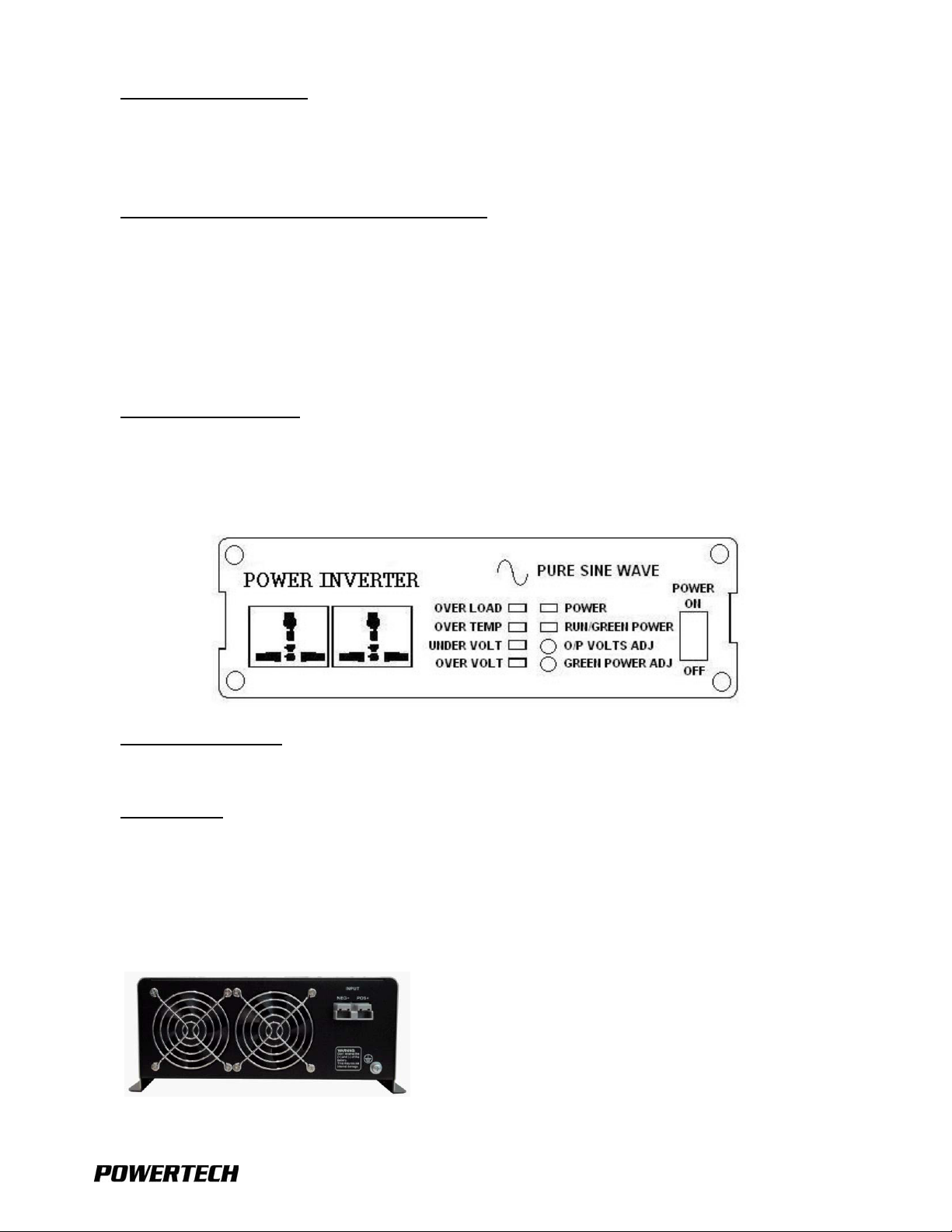
E. Front View & Main Functions
1. Power ‘ON/OFF’ Switch
Make sure the Power Switch is in the ‘OFF’ position during installation.
2. LED Indicators
Over Volt: Over Voltage Protection. Over Temp: Over Temperature Protection.
Under Volt: Under Voltage Protection. Over Load: Over Load Protection.
Power: Power ON. Run/Green Power: Indicates current operating condition of the inverter.
F. Rear View & Main Functions
1200L
-5-
1. Ventilation Openings
Do not obstruct the ventilation openings; allow at least 25mm for airflow around all openings.
2. Battery terminals
Only connect the Inverter to a 12VDC battery, battery bank or other 12VDC power source. (POS+)is Positive, (NEG-)
is Negative.
3. Remote Control (Located on the side of the inverter)
Connect remote control unit (supplied) as necessary.
G. Pre-Installation Information
Before installing your Inverter, please makesure that youhave appropriately-sized batteries with sufficient ampere-hour
capacity. A battery that is too small will not allow the Inverter to perform to its full specification.
H. Electrical Requirements
•The DC input voltage of the Inverter must be the same as the battery bank voltage.
•The DC cabling must be connected to the correct polarity terminals of the battery bank. Red (POS+) Positive,
Black (NEG-) Negative).
•DO NOT extend the DC cable length to the Inverter unless you are prepared to increase the diameter of the cable.
If this is necessary consult your supplier/ installer for advice.
•DO NOT connect AC power to the AC output of the Inverter: THIS WILL DAMAGE THE INVERTER.
•Between the Inverter and any generator / mains supply, it is essential you install a double-pole
“break-before-make” changeover switch that switches both line and neutral AC power.
•DO NOT place the AC power cable and the 12VDC cable in the same cable duct.
•To prevent electrical shock, DO NOT operate the Inverter without connecting it to ground.
•Always disconnect the inverter when not in use.
WARNING! Shock Hazard!
Before proceeding, ensure the Inverter is NOT connected to any Batteries or DC
Power Source.
Do not connect the AC output Terminals of the Inverter to an incoming AC
Power Sources such as the mains.
WARNING!
Do not reverse the polarity of the input connections.
Reverse polarity connection will blow internal fuses and may damage Inverter
permanently.
-6-
I. Installation Requirements
1. Where to install
The Power Inverter should be installed in a location that meets the following requirements:
•Dry – Do not expose the Inverter to high levels of moisture, rain, snow, spray or bilge fluids. Make sure the
Inverter is not exposed to salt water vapour.
•Temperature – Ambient air temperature should be between 0°Cand 40°C. Do not expose the Inverter to heat
sources or direct sunlight.
•Safety – Do not install in a battery compartment or other areas where flammable fumes may exist, such as fuel
storage or engine compartments.
•Ventilation – Allow at least 25mm of clearance around the inverter for airflow. Ensure the ventilation openings on
the sides and bottomof the unit are not obstructed. The installation site should not be susceptible to temperatures
in excess of 50°C.
•Dust-free – Do not install the inverter in an environment where there is dust, wood particles or other
filings/shavings present. These can pull into the unit blocking the cooling fans.
•Close to battery/batteries – Avoid excessive cable lengths (Mount the inverter between one and two meters
from the batteries) but do not install the inverter over or in the same compartment as batteries. Use the
recommended wire lengths and sizes. Do not mount the inverter where it will be exposed to the gases produced
by the battery or battery bank. These gases are very corrosive and prolonged exposure will damage the inverter.
•Wall-mount –Inspection and operation of the Inverter is easier if the unit is mounted at a convenient height and
the DC cables hang naturally out of the way.
2. Safety Grounding
To prevent electrical shock, DO NOT operate the Inverter without connecting it to an appropriate ground.
3. 230V Models
There is no connection made inside the Inverter from either of the lineconductors (line orneutral) to theearth ground.
Please read these instructions carefully before commencing installation.
Installation should be performed by competent qualified installer as dangerous voltages can be present. Complete
the following steps in the order shown:
4. Mounting
•Unpack the Inverter from the shipping container and inspect the unit for any obvious transit damage. Report any
concerns immediately to your supplier.
•Mount the Inverter to a suitable surface, paying close attention to the mounting requirements previously
mentioned in this manual.
5. AC Wiring
Important: to satisfy warranty requirements and conditions, a qualified electrician must perform all AC wiring.
WARNING!
Operation of the inverter without a proper ground connection may result in an
electrical safety hazard.

-7-
6. DC Wiring
IT IS ESSENTIAL that the battery bank voltage match the DC input voltage rating of the Inverter. Damage to the
Inverter could result from improper voltage connections.
A Battery Fuse must be installed between the batteries and the Inverter; appropriately sized Motor-Starting fuses or
similar are recommended.
Before making any connections ensure that the Inverter Power Switch is in the ‘OFF’ position.
The DC cables should be as short as possible (ideally, less than 3 metres) and large enough to handle the required DC
current in accordance with electrical codes or regulations applicable to your installation.
Cables that are not an adequate gauge ( ie too small in diameter) or are too long will cause decreased inverter
performance such as:
•poor surge capability
•frequent low input voltage warnings
•shutdowns.
J. Connection and Testing
For a quick connection and performance check, please follow these guidelines:
Note: The connection to the Negative (NEG-) terminal of the Inverter should be the last connection made. A spark
when making this final connection is normal.
Step 1: Unpack and inspect the Power Inverter for any damage.
Step 2: Make sure the power switch in the ‘OFF’ position.
Step 3: Connect the DC Positive cable to the Positive (POS+) terminal on the battery. Next, connect the DC Positive
cable to the Positive terminal on the Inverter (via the Battery Fuse). Make sure the connections are secure.
Before proceeding further, recheck the cable you have just connected to the Positive terminal of Inverter, and to the
Positive terminal of the battery or DC power source.
WARNING!
Do not operate the power inverter without connecting it to ground. Electrical
shock hazard may result.
WARNING!
Make sure all the DC connections/ terminations are tight (torque to 9-10
ft-lbs,11.7-13Nm). Loose connections will overheat and could result in a fire
hazard.

-8-
Step 4: Connect the DC Negative cable to the Negative terminal of the Inverter. Next, connect the DC Negative cable
to the Negative (NEG-) terminal on the battery or power source. Make sure the connections are secure.
Step 5: Set the Inverter power switch to the ‘ON’ position. Check the POWER and RUN/GREEN POWER LED
indicators on the front panel of the Inverter are illuminated. If the LED is not illuminated, check your power
source and the connections to Inverter. The other indicators should be off.
Step 6: Set the Inverter power switch to the ‘OFF’ position. The indicator lights may blink and the internal alarm may
sound momentarily. This is normal.
Step 7: Plug the AC test load into the AC receptacle on the front panel of the Inverter. Leave the AC test load switch
in the ‘OFF’ position.
Step 8: Set Inverter power switch to the ‘ON’position and turn the test load ‘ON’. The Inverter should supply power to
the test load. If you plan to measure the AC output voltage of the Inverter, a Digital Multi Meter with true RMS
voltage capabilities must be used.
K. Operation
To operate the Inverter, turn it ‘ON’ using the Power ‘ON/OFF’ switch on the front panel. The Inverter is now ready to
deliver AC power to your appliances/ loads. If you are operating several appliances/ loads from the Inverter, turn them
‘ON’ separately after the Inverter has been switched ‘ON’. This will ensure that the Inverter does not have to deliver the
starting currents for all loads at once and hence, minimizes the risk of a shutdown.
1. Controls and Indicators
The power ‘ON/OFF’ switch turns the control circuit in the Inverter ‘ON’ and ‘OFF’. It does not disconnect DC power
from the Inverter.
The Inverter operates from an input voltage ranging from 10VDC to 16VDC for 12V models.
2. Over Voltage Indicator
The over voltage indicator indicates that the Inverter has shut down because the protection circuits have sensed the DC
input voltage is higher than that recommended for safe operation.
WARNING!
You may observe a spark when you make this connection. Do not make this
connection in the presence of flammable fumes. Explosion or fire may result.
CAUTION!
Reversed polarity connections will blow a fuse and may permanently damage
the Inverter. Damage caused by a reverse polarity connection is Not covered by
warranty.
¡
Ï
¡Ð

-9-
3. Under Voltage Indicator
The under voltage indicator indicates that the Inverter has shut down because the protection circuits have sensed the
DC input voltage is lower than that recommended for safe operation.
4. Over Temp Indicator
The over temp indicator indicates that the Inverter has shut down because the thermal protection circuits have sensed
the Inverter has become overheated. The Inverter may overheat because it has been operated at power levels above
its rating, or because it has been installed in a location which does not allow it to dissipate heat properly.
The power inverter will restart automatically once it has cooled down. If the Inverter continues to shut down, reduce the
load, and check the ambient temperature.
5. Overload Indicator
The overload indicator indicates that the Inverter has shut down because its output circuit has been short circuited, or
drastically overloaded. Switch the ‘ON/OFF’ switch to ‘OFF’, correct the fault condition, and then switch the ‘ON/OFF’
switch back to ‘ON’.
L. Green Power Adjustment
The Inverter features automatic load-sensing, which means it will wait in Standby Mode until an AC load is switched
‘ON’. When an AC load appears, the Inverter will immediately start. This feature conserves valuable battery energy as
the Inverter uses only about 10% of normal power when in Standby Mode (Standby Mode is indicated by flashing
GREEN indicator). The amount of AC power required to start the Inverter can be adjusted on the front panel. Follow the
procedure below. Ensure the battery voltage is at the nominal 12V level.
1. Adjusting Load Sensitivity for Green Power Mode
•Turn ‘OFF’ allAC loads, keeping theAC wiring connected to the Inverter AC output. Some loads such as TVs
must be turned ‘OFF’ at the power point as they can still represent a small load to the Inverter.
•Using a small screwdriver, adjust the black plastic trim pot located to the right of the over voltage indicator and to
the left of the power switch. Turning this control fully clockwise will override the Standby circuit and keep the
Inverter ‘ON’ all the time. This could be used if you have a very small load that must stay ‘ON’ at all times.
•Adjust the trim pot until the indicator is a steady GREEN; then turn the trim pot back a little until the indicator
flashes GREEN. Allow 10 seconds between adjustments for stabilisation: clockwise decreases the sensitivity or
threshold; counter-clockwise is increases the sensitivity or threshold.
•Note: the trim pot is extremely sensitive.
•When the indicator flashes GREEN, the Inverter is in Standby Mode.
•Turn ‘ON’ the smallest AC load connected to the Inverter. The Inverter should now deliver 240VAC, and AC status
indicator should be a steady GREEN. However, if the indicator is ORANGE the sensitivity must be increased by
turning the control trim pot a little counter-clockwise.
•Now turn ‘OFF’ the AC load. The indicator should return to flashing GREEN, indicating that the Inverter is in
Standby Mode. If this does not occur, reduce sensitivity by turning the control trim pot a little clockwise and check
again.
M. Trouble Shooting:
1. AC Output Does Not Remain ‘ON’
If Green Power Mode is being used, some AC loads may not be large enough to hold the Inverter ‘ON’. This condition
is indicated by the Inverter turning ‘OFF’ after every eight to ten seconds, then back ‘ON’ again. The AC Status
indicator will also be flashing ORANGE.
There are two possible solutions:
•Increase the sensitivity of the inverter by turning the Standby control slightly counter-clockwise until the indicator
is a steady GREEN; or
•Increase the amount of AC load on the Inverter.

-10-
2. Over Temperature Shut Down
Your inverter will safely provide the output power defined in the technical data section under the conditions specified.
If the Inverter shuts down and indicates over temperature, it may be that you have exceeded one of the parameters.
Check the following:
•Ensure the Inverter has adequate ventilation. Insufficient ventilation can severely restrict the power output of your
Inverter as it does not allow proper heat dissipation.
•Ensure that the true power rating of your appliance (including power factor) is less than the output rating of your
Inverter.
3. Shut Down When Trying to Start a Load
A sudden surge in load, such as a motor starting, may cause the inverter to shut down. If this occurs:
•Ensure the battery voltage is within specifications when the device is trying to start. If the input voltage drops too
low, you may need to increase the capacity of your batteries. Also check DC cables and terminations.
•If the battery voltage is ok when measured at the Inverter, then the Inverter AC output power rating may be too.
4. Overload Shut Down
The overload indicator indicates that the Inverter has shut down. If this occurs:
•Ensure the output circuit is not short circuited, or drastically overloaded. Switch the ‘ON/OFF’ switch to ‘OFF’,
correct the fault condition, and then switch the ‘ON/OFF’ switch back to ‘ON’.
5. Under Voltage Shut Down
The under voltage indicator indicates that the Inverter has shut down because the protection circuits have sensed the
DC input voltage is lower than that recommended for safe operation. If this occurs:
•Charge the battery.
•Check the battery voltage at the terminals of the Inverter is within specification. If the input voltage drops too low,
you may need to increase the capacity of your batteries. Also check DC cables and terminations.
6. Over Voltage Shut Down
The over voltage indicator indicates that the Inverter has shut down because the protection circuits have sensed the DC
input voltage is higher than that recommended for safe operation. If this occurs:
•Check the DC power source or battery voltage at the terminals of the Inverter is within specification.
7. Television Interference
Operation of the Inverter can interfere with television reception on some channels. If this occurs, the following steps
may help alleviate the problem:
•Make sure that the chassis ground lug on the back of the Inverter is solidly connected to the ground system of
your vehicle, boat or home. Make sure there is no oxidation or corrosion on any groumd terminations.
•Try not to operate high power loads with the Inverter while watching television.
•Make sure that the antenna feeding your television provides an adequate (“Snow free”) signal and that you are
using high quality shielded cable between the antenna and the television.
•Move the television as far away from the Inverter as possible.
•Keep the cables between the battery and the Inverter as short as possible. Twist them together with about 6 to 9
twists per metre as this helps minimising radiated interference from the cables.

-11-
N. Maintenance
Very little maintenance is required to keep the Inverter operating properly. With the Inverter switched ‘OFF’, clean the
exterior of the unit periodically with a slightly damp cloth to prevent accumulation of dust and dirt. At the same time,
check and tighten all cable terminations on the DC input terminals.
WARNING!
There are no user serviceable parts inside. Only qualified personnel should
carry out maintenance or service the device. Do not open or disassemble the
Inverter. Attempting to service the unit yourself may result in a risk of
electrical shock or fire.

-12-
O. Specifications
Model No. 1200W (L)
Continuous Output
Power 1200W
Output Power
Surge 3600W
AC Output Voltage 200VAC ~ 240VAC ±1~2% Adjustable
Output Voltage Regulation ~ -1.5% to +1.0%
Output Frequency 50Hz ± 0.5%
Output Wave
Form Pure Sine Wave <2% THD
Efficiency
(Full Load) >70%
No Load Power
Consumption <4W (In Green Power Standby Mode)
Input Voltage
Range ~10VDC to 16VDC
Green Power
Recovery Time 1 Second
LED Status
Indication Power ON/ OFF, RUN/GREEN POWER Standby, Under/Over Voltage
Shutdown, Over Temperature Shutdown, and Over Load Shutdown
Protection Input Under/Over Voltage, Over Temp, Reverse Input Polarity (Fuse),
Over Load, Short Circuit Shutdown, Restarts, Soft Start
Remote Control ON/OFF Switching with 3M cable
Operation Temperature
Range 0°C ~ 40°C (32°F ~ 104°F)
Storage Temperature
Range -30°C ~ 70°C (-22°F ~ 158°F)
Dimensions
(L x W x H) 465 x 280 x 120mm
Nett Weight 11.5kg
Gross Weight 14.0kg
Table of contents
Other PowerTech Inverter manuals


Popular Inverter manuals by other brands


New Holland
New Holland Windrow Inverter Specifications

Darfon
Darfon H5001 installation manual

Ingeteam
Ingeteam Ingecon Sun Lite 2.5TL Maintenance Guide

Rowan Elettronica
Rowan Elettronica 400 Series Installation and instruction manual

Tesla Kala
Tesla Kala SY8600 Series user manual

Fosera
Fosera PSHS 3000 user manual

Shindaiwa
Shindaiwa DGA37CM Owner's and operator's manual

Thermal Arc
Thermal Arc ARCMASTER 400TS Service manual

Profi-pumpe
Profi-pumpe INVERTER PUMP CONTROL 5 operating instructions

iWeld
iWeld MIG 251 DIGITAL user manual

Mitsubishi Electric
Mitsubishi Electric FR-HEL-0.4K instruction manual

Vector
Vector VEC411 User's manual & warranty information