Darfon H5001 User manual

I N S T A L L A T I O N M A N U A L H 5 0 0 1 H Y B R I D I N V E R T E R
R e v . 2 © 2 0 1 8 D a r f o n E l e c t r o n i c s C o r p . 1 | P a g e
INSTALLATION MANUAL
H5001 HYBRID INVERTER

I N S T A L L A T I O N M A N U A L H 5 0 0 1 H Y B R I D I N V E R T E R
R e v . 2 © 2 0 1 8 D a r f o n E l e c t r o n i c s C o r p . 2 | P a g e
TABLE OF CONTENTS
IMPORTANT SAFETY WARNINGS...................................................................................3
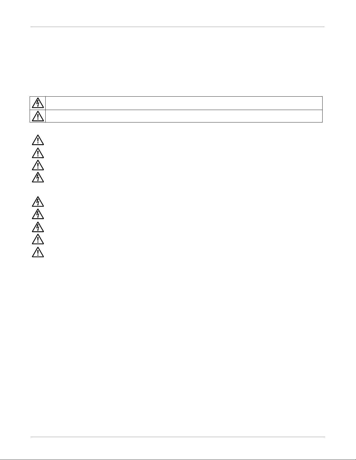
PRODUCT OVERVIEW.......................................................................................................4
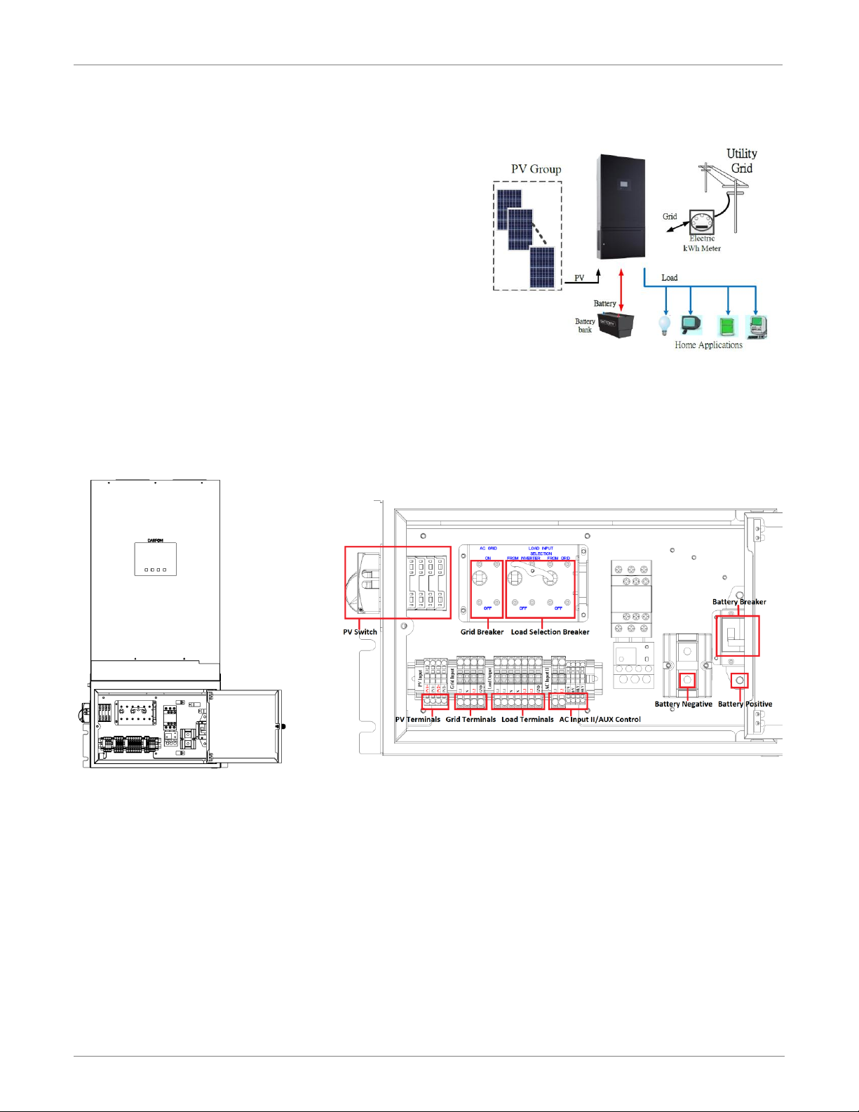
MOUNTING THE INVERTER..............................................................................................5
Installing the Inverter onto the Wall ....................................................................................... 5
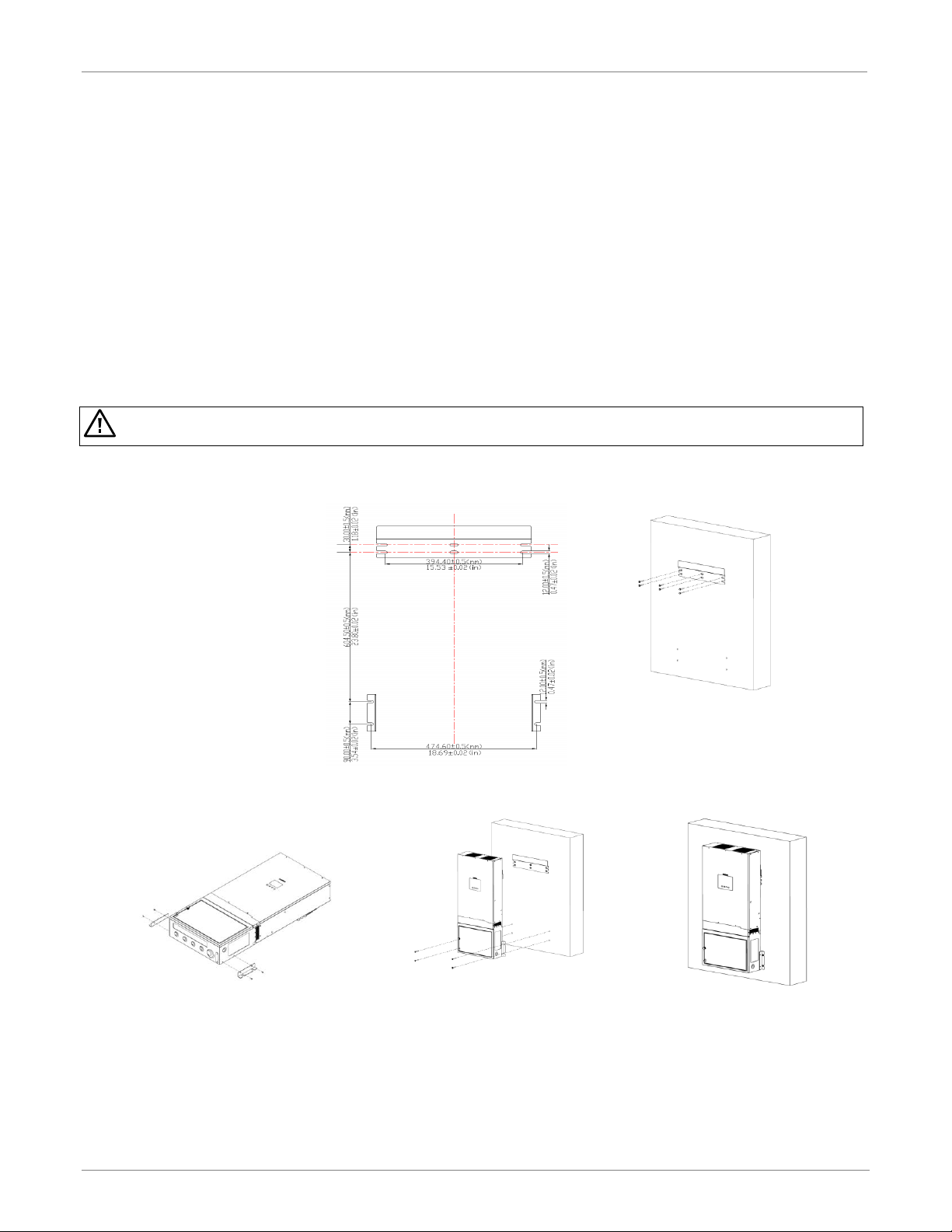
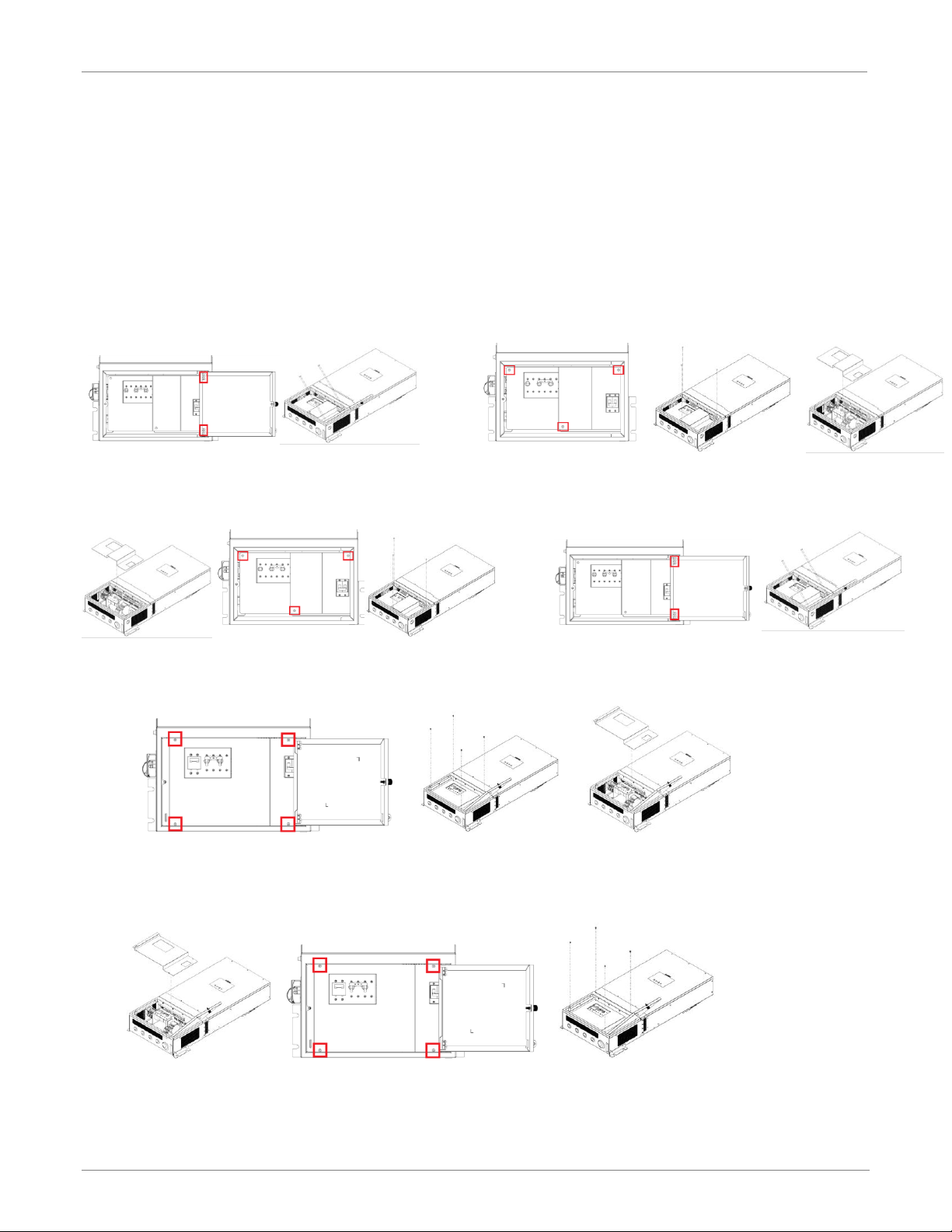
REMOVING AND INSTALLING THE DEAD-FRONT COVER...........................................6
PV MODULE (DC) CONNECTION .....................................................................................7
Connecting the PV Arrays......................................................................................................... 7
GRID (UTILITY) CONNECTION .........................................................................................8
Connecting to the Grid/Utility ..................................................................................................8
Circuit Protection......................................................................................................................8
BATTERY CONNECTION AND CHARGING REQUIREMENTS.......................................9
Connecting the Batteries .........................................................................................................9
BATTERY CHARGING REQUIREMENTS.......................................................................10
Charging Characteristics..........................................................................................................10
LOAD (AC OUTPUT) CONNECTION...............................................................................11
Connecting to the Load........................................................................................................... 11
OPERATION AND DISPLAY PANEL...............................................................................12
Display Panel Overview ...........................................................................................................12
Starting the System .................................................................................................................12
Stopping the System ...............................................................................................................12
LCD Screen –Icons and Pages ................................................................................................13
System Settings .......................................................................................................................15
Error and Warning Definition..................................................................................................17
GENERATOR [GENERATOR KIT SOLD SEPARATELY]..............................................19
Generator Sizing ......................................................................................................................19
Automatic Start Generator .....................................................................................................19
CONFIGURING THE HARDWARE ..................................................................................20
Connecting to the Hardware ................................................................................................. 20
Using the Application Software..............................................................................................21
Modifying the Parameters (Installer Login Only) ................................................................. 23
AP Parameters ........................................................................................................................ 25
MAINTENANCE & CLEANING.........................................................................................26
Wiring Diagram ....................................................................................................................... 26
SPECIFICATIONS.............................................................................................................27
GRID SUPPORT PARAMERTERS (UL1741SA).............................................................28

I N S T A L L A T I O N M A N U A L H 5 0 0 1 H Y B R I D I N V E R T E R
R e v . 2 © 2 0 1 8 D a r f o n E l e c t r o n i c s C o r p . 3 | P a g e
IMPORTANT SAFETY WARNINGS
PLEASE READ ALL INSTRUCTIONS AND CAUTIONARY MARKINGS ON THE UNIT AND THIS GUIDE BEFORE
INSTALLING THE INVERTER. AND, STORE THIS USER MANUAL WHERE IT CAN BE ACCESSED EASILY.
This manual is for qualified personnel. The tasks described in this manual should be performed by qualified personnel only.
Safety Symbols
WARNING. This indicates the risk of electric shock. The presence of high voltage levels may constitute a risk of injury or death to users
and/or installers.
CAUTION. This indicates important information where failure to comply may result in safety hazards or cause damage to this product.
General Precautions
CAUTION. Before installing and using this inverter, read all instructions and cautionary markings on the inverter and all appropriate
sections of this guide. Installing this inverter by licensed electricians only.
CAUTION. Normally grounded conductors may be ungrounded and energized when a ground fault is indicated.
CAUTION. This inverter is heavy. It should be lifted by at least two persons for the safety.
WARNING. Authorized service personnel should reduce the risk of electrical shock by disconnecting AC, DC and battery
power from the inverter before attempting any maintenance or cleaning or working on any circuits connected to the inverter.
Turning off controls will not reduce this risk. Internal capacitors can remain charged for 5 minutes after disconnecting all
sources of power.
WARNING. Do not disassemble this inverter yourself. It contains no user-serviceable parts. Attempt to service this inverter yourself
may cause a risk of electrical shock or fire and will void the warranty from the manufacturer.
WARNING. To avoid a risk of fire and electric shock, make sure that existing wiring is in good condition and that the wire is not
undersized. Do not operate the Inverter with damaged or substandard wiring.
WARNING. To reduce risk of fire hazard, do not cover or obstruct the cooling fans.
CAUTION. Do not install the Inverter if it has received a sharp blow, been dropped, or otherwise damaged in any way. If the Inverter is
damaged, call for an RMA (Return Material Authorization).
CAUTION. This inverter is not allowed to operate in parallel. Do not parallel connect more than one unit in AC output connector.
Otherwise, it will damage this inverter.
Manufactured by
Darfon Electronics Corp.
167 Shan-ying Road, Gueishan
Taoyuan 333, Taiwan, (R.O.C.)
Tel: +886 3 2508800
USA Office
Darfon America Corp.
103A Pioneer Way
Mountain View, CA 94041
Tel: +1.650.316.6300
For more information
www.darfonsolar.com
© 2018 Darfon Electronics Corp. All rights reserved. All specifications are subject to change without prior notice. Darfon and the Darfon logo are
trademarks of Darfon Electronics Corp. All other trademarks are the property of the respective owners.

I N S T A L L A T I O N M A N U A L H 5 0 0 1 H Y B R I D I N V E R T E R
R e v . 2 © 2 0 1 8 D a r f o n E l e c t r o n i c s C o r p . 4| P a g e
PRODUCT OVERVIEW
The H5001 hybrid inverter provides power to the essential load by
utilizing power from PV panels, the utility and batteries. When the PV
panels (two string input) generates enough power, the inverter
supports the essential load, feeds back to the grid and charges the
batteries, all at the same time. When the energy generated by the PV
panels is not sufficient to support the essential load, the inverter takes
power from the utility.
To accommodate various power situations, the H5001 is designed to
handle continuous power from PV panels, batteries and the utility.
When the MPPT input voltage from the PV panels is within the
acceptable range, between 250 and 430VDC, the inverter can feed the
grid and charge the batteries.
Note: When PV input voltage is lower than 250V, the power of
the inverter will de-rate.
H5001
Distribution Box
A wiring subpanel is pre-assembled at the factory. It consists of breakers,
disconnects and batteries paralleled circuits.
BASIC HYBRID PV STORAGE SYSTEM OVERVIEW

I N S T A L L A T I O N M A N U A L H 5 0 0 1 H Y B R I D I N V E R T E R
R e v . 2 © 2 0 1 8 D a r f o n E l e c t r o n i c s C o r p . 5| P a g e
MOUNTING THE INVERTER
Before installation, make sure nothing inside the package is damaged. You should have received the following items in the package:
H5001 hybrid inverter, backplate, brackets, screws and this installation manual.
The following considerations must be taken into account when selecting where to install.
The unit cannot be mounted on flammable construction materials.
The unit must be mounted to a solid surface.
The unit should be installed at eye level in order to easily read the LCD display at any time.
Allow 20cm (8in) of clearance to the sides and 50cm (20in) to the top and bottom of the unit for proper air circulation to dissipate
heat.
The ambient temperature must be between 0 and 50°C and relative humidity must be between 5 and 85% to ensure optimal
operation. Do not operate where the temperature and humidity are beyond the specified limits.
The unit has a Pollution Degree rating of PD2. The unit must be mounted in a protected area that is dry, free of excessive dust and
has adequate air flow.
The unit was designed with an IP20 protection rating and is for indoor applications only.
CAUTION. This inverter is heavy (87lb/40kg). Be carefully while lifting and mounting the unit. Installation should be handled
by two people. Do not hang or place additional weight onto the inverter.
Installing the Inverter onto the Wall
Step 1. Use the backplate as a
template, and install anchors
as needed.
Note: If installing onto
drywall, Unistrut needs to be
mounted and secured to two
studs in the wall. The
backplate and inverter’s
brackets are secured to the
Unistrut using Unistrut lugs.
Step 2. Mount the backplate onto the wall.
Note: Use at least two screws, one on
the left the other on the right.
Step 3. Install the brackets onto each
side of the inverter.
Step 4. Hang the inverter onto the
backplate.
Step 5. Secure the brackets on
inverters to the wall.
Note: Use at least two screws, one
on each side of the inverter.

INS T A L L A T I O N M A N U A L H 5 0 0 1 H Y B R I D I N V E R T E R
R e v . 2 © 2 0 1 8 D a r f o n E l e c t r o n i c s C o r p . 6| P a g e
REMOVING AND INSTALLING THE DEAD-FRONT COVER
Before making any connections (PV, Grid, Battery or Load), you will need to first remove the dead-front cover from the distribution
box. After the connections have been completed, the dead-front cover must be reinstalled back into the distribution box. There are
two versions of dead-front covers, please check which version you have. Version 1 has three screws: one top-left, one top-right and
one at the bottom. Version 2 has four screws: one top-left, one top-right, one bottom-left and one bottom-right. Use the following
steps to remove and reinstall the dead-font cover.
Removing the Dead-Front Cover (Version 1)
Step 1. Remove the distribution box’s door by removing the
four screws from the door hinge.
Step 2. Remove the three screws from the dead-front cover,
then pull the cover off.
Installing the Dead-Front Cover (Version 1)
Step 1. Place the dead-front cover back into the distribution
box and secure with three screws.
Step 2. Place the back onto the distribution box, align and
secure the pins at the door hinge with the four screws.
Removing the Dead-Front Cover (Version 2)
Step 1. Remove the four screws from the dead-front cover, then pull the cover off.
Installing the Dead-Front Cover (Version 2)
Step 1. Place the dead-front cover back into the distribution box and secure with four screws.

I N S T A L L A T I O N M A N U A L H 5 0 0 1 H Y B R I D I N V E R T E R
R e v . 2 © 2 0 1 8 D a r f o n E l e c t r o n i c s C o r p . 7| P a g e
PV MODULE (DC) CONNECTION
There is a DC (PV) circuit breaker in the distribution box. This system can connect to two strings of PV modules with MPPT control.
Configure each PV input as recommended in the table below. Vmp is a PV panel’s max power point voltage. The PV charging
efficiency is maximized when the PV system’s voltage is close to Best Vmp.
TERMINAL MARK
PV Input Power
Typical Amperage
Cable Size
Torque
BEST VMP
VMP range
PV input 1
3.25kW
13A
12 AWG
1.4 - 1.6 Nm
360V
250V - 430V
PV input 2
3.25kW
13A
12 AWG
1.4 - 1.6 Nm
360V
250V - 430V
WARNING. Because this inverter is non-isolated, only two types of PV modules are acceptable: single crystalline and poly crystalline with only
Class A-rated. To avoid any malfunction, do not connect any PV modules with possibility of leakage current to the inverter. For example,
non-grounded PV modules will cause leakage current to the inverter.
CAUTION. To reduce the risk of damage due to surge, Darfon recommends surge protection between the modules and the inverter.
CAUTION. To reduce the risk of injury, use the proper cable size for PV module connection.
CAUTION. Exceeding the maximum input voltage can destroy the unit. Check the PV string voltage before wiring the connection.
Connecting the PV Arrays
Step 1. For each PV input string, make sure the input voltage is between
250VDC and 430VDC, and the maximum current is 13A.
Note: The inverter can still be installed if you are only using
one PV input string.
Step 2. Make sure the circuit breaker is off.
Step 3. Strip 15mm(0.6in) of insulation from each PV cable (PV1+, PV1-, PV2+
and PV2-).
Step 4. Insert the PV cables into the PV quick connect terminals. Make sure
the polarity for each connection is correct; positive to positive and
negative to negative.
WARNING. Never touch the terminals of the inverter directly. It will
cause lethal electric shock.
WARNING. The final connection for DC strings should be done at the
array not at the inverter.
DC CABLE FOR PV CONNECTIONS
CONNECTING TO PV MODULE

I N S T A L L A T I O N M A N U A L H 5 0 0 1 H Y B R I D I N V E R T E R
R e v . 2 © 2 0 1 8 D a r f o n E l e c t r o n i c s C o r p . 8| P a g e
GRID (UTILITY) CONNECTION
There is an AC (Grid) circuit breaker in the distribution box. This will ensure the inverter can be safely disconnected during
maintenance and is fully protected from overcurrent of AC input.
AC GRID
UTILITY
TYPE
USA: 240V/120V 60HZ
SPLIT-PHASE SYSTEM
EURO: 230V 50HZ SINGLE
PHASE SYSTEM
GRID CONNECTION WIRING
REQUIREMENTS
GRID RATED POWER
NOMINAL VOLTAGE
WIRE SIZE
TORQUE
5KW
230/240 VAC
8 AWG
0.82 Nm
Connecting to the Grid/Utility
Step 1. Check the grid voltage and frequency with an AC voltmeter. It should
be within the operation AC voltage range of the product’s
specifications.
Step 2. Make sure the circuit breaker is off.
Step 3. For each AC wire, strip 15mm(0.6in) of isolation.
Step 4. Connect the AC wires to the inverter according to the labels indicated
on the terminal block or your grid utility type.
Note: The PE protective conductor (Ground) should be the first to be
connected.
Circuit Protection
There are three circuit breakers that protect the Grid
path. One circuit breaker is in the distribution box and is
rated at 40A. Then there are two line circuit breakers
behind the access panel that are rated at 40A. If the
Grid is properly connected and the inverter displays
warning code 55 (Grid is disconnected), check all three
circuit breakers.
WARNING. To reduce the risk of injury, use the recommended wire
size. It is very important for system safety and efficient operation to
use the appropriate wire for grid (utility) connection.
WARNING. To prevent the risk of electric shock, make sure the
ground wire is properly earthed before operating this unit whether
the grid is connected or not.
CONNECTING TO AC UTILITY TERMINAL
AC WIRE FOR GRID CONNECTION
Grid Circuit Breaker
in Distribution Box
Grid Line Circuit
Breakers behind
Access Panel

I N S T A L L A T I O N M A N U A L H 5 0 0 1 H Y B R I D I N V E R T E R
R e v . 2 © 2 0 1 8 D a r f o n E l e c t r o n i c s C o r p . 9| P a g e
BATTERY CONNECTION AND CHARGING REQUIREMENTS
There is a DC (Battery) circuit breaker in the distribution box. Before connecting the batteries, please have the battery specifications
on hand.
Notes: 1.For lead acid batteries, Flooded, Gel or AGM can be used. Please check maximum charging voltage and
current when first using this inverter.
2. If using Lithium batteries, consult with the battery manufacturer for details.
BATTERY POWER
TYPICAL AMPERAGE
BATTERY CAPACITY
CABLE LENGTH
CABLE SIZE
TORQUE VALUE
5KW
104A
200 to 600AH
< 3m (one-way)
2 AWG
2 to 3Nm (18 to 26 in-lb)
WARNING. To reduce the risk of injury, use the recommended cable size above. It is very important for system safety and efficient operation
to use the appropriate cable for battery connection.
Connecting the Batteries
Step 1. Make sure the circuit breaker is off.
Step 2. Make sure the nominal voltage for the batteries is 48VDC.
WARNING. Shock Hazard. Installation must be performed with care due to
high battery current.
Step 3. Strip 8mm(0.3in) of insulation from each battery cable and insert it
into a ring lug.
Step 4. Connect the battery ring lugs to the battery terminals. Make sure the
polarity for each connection is correct; positive to positive and
negative to negative.
RED cable to the positive terminal (+);
BLACK cable to the negative terminal (-).
CAUTION. Before making the final DC connection or closing DC breaker,
make sure the connections have the correct polarity.
CAUTION. Do not apply anti-oxidant substance on the terminals before
terminals are connected tightly.
CAUTION. Do not place anything between the flat part of the inverter terminal and the ring terminal. Otherwise, overheating may occur.
Step 5. Update AP registers as needed. See page 23 for instructions on modifying the parameters and page 25 for remote settings
of AP parameters.
CABLES FOR BATTERY CONNECTION
CONNECTING TO BATTERY TERMINAL

I N S T A L L A T I O N M A N U A L H 5 0 0 1 H Y B R I D I N V E R T E R
R e v . 2 © 2 0 1 8 D a r f o n E l e c t r o n i c s C o r p . 10 | P a g e
BATTERY CHARGING REQUIREMENTS
The default charging parameters are shown below. Use this as a reference to make sure the battery selected is compatible with
H5001 inverter. It is recommended that you use a deep cycle battery when the mode of operation is not set as one of the two
back-up modes. If you want to change battery charging parameters, refer to “Modifying the Parameters” on page 23 and “Remote
Settings” on page 25.
Charging Characteristics
PARAMETERS
LEAD-ACID BATTERY (DEFAULT VALUES)
LITHIUM BATTERIES (DEFAULT VALUES)
Max. Current
60A
60A
Float Voltage
54.4Vdc
N/A
Bulk Voltage
56.4Vdc
Darfon: 57.4Vdc, Panasonic: 52Vdc, Dragonfly: 57.6Vdc
Charging process
First - charging voltage increases to 56.4V.
Second- charging voltage will maintain at 56.4V until
charging current is down to 2A.
Third- goes to float voltage at 54.4V.
First –SOC voltage increases to bulk voltage.
Second - charging voltage will maintain until SOC is 99%.
Third- stop charging after 1 hour.

I N S T A L L A T I O N M A N U A L H 5 0 0 1 H Y B R I D I N V E R T E R
R e v . 2 © 2 0 1 8 D a r f o n E l e c t r o n i c s C o r p . 11 | P a g e
CONNECTING TO AC LOAD
LOAD (AC OUTPUT) CONNECTION
There are two AC circuit breakers inside the distribution box for the load connection; one for the load and the other for grid bypass.
These two breakers are interlocked (to ensure only one breaker will be active at a given time).
Note: If the inverter needs to be repaired, please turn on the AC breaker (from Grid), the Grid can continue to supply
the load when the inverter has been taken off.
AC LOAD
CONNECTION
TYPE
USA: 240V/120V SPLIT-PHASE SYSTEM
EURO: 230V SINGLE PHASE SYSTEM
AC OUTPUT MAX POWER
NOMINAL VOLTAGE
WIRE SIZE
TORQUE
5KW
230/240 VAC
8 AWG
0.82 Nm
WARNING. To reduce the risk of injury, use the recommended cable size above. It is very important for system safety and
efficient operation to use the appropriate cable for AC connection.
Connecting to the Load
Step 1. Make sure the circuit breaker is off.
Step 2. For each AC wire, strip 15mm(0.6in) of isolation.
Step 3. Connect the wires according to the labels indicated on the terminal
block or your grid utility type.
Step 4. Be sure to connect PE protective conductor first.
CAUTION. Make sure the AC Load and AC Grid are properly
connected. Misconnecting them will damage to this product.
AC WIRE FOR LOAD CONNECTION

I N S T A L L A T I O N M A N U A L H 5 0 0 1 H Y B R I D I N V E R T E R
R e v . 2 © 2 0 1 8 D a r f o n E l e c t r o n i c s C o r p . 12 | P a g e
OPERATION AND DISPLAY PANEL
Display Panel Overview
The display panel consists of four function keys and an LCD screen. The display panel will be used to manage and monitor the hybrid
system.
Starting the System
Step 1. Make sure all the connections have been completed and
properly installed.
Step 2. Turn/set the PV Switch, Grid Breaker and Battery Breaker to the
on position.
Step 3. Turn on the Main Switch (located on the left side of the
inverter).
Step 4. If the inverter has multiple sources of power or just a PV or grid
connection, the inverter will start automatically. If the battery is
the only power source, then wait for the display to come on,
press and hold key for 7 seconds and two beeps, then the
system will boot on the battery only.
Step 5. Check AC output voltage: L-L 240Vac / L-N 120Vac. /L-N 230Vac
Step 6. Turn on Load Breaker in the distribution box.
Stopping the System
Step 1. Turn off the Main Switch (Located on the left side of the inverter).
Step 2. Turn off all power switch and breakers.
ICON
FUNCTION
DESCRIPTION
Enter
Confirm the selection in setting mode or
enter setting mode.
ESC
Exit
Exits setting mode.
Left
Go to previous page, move or decreasing all
Number.
Right
Go to next page; move; to increase all
Number.

I N S T A L L A T I O N M A N U A L H 5 0 0 1 H Y B R I D I N V E R T E R
R e v . 2 © 2 0 1 8 D a r f o n E l e c t r o n i c s C o r p . 13 | P a g e
LCD Screen –Icons and Pages
The LCD screen will display three different pages: “Power Flows”, “Power Information” and “System Settings”. Use the ←or →
keys to toggle between the various pages. The screen will default to the “Power Flows” page.
POWER FLOWS PAGE
POWER INFORMATION PAGE
SYSTEM SETTINGS PAGE
ICON
DESCRIPTION
Represents the PV Array
Represents the Battery Pack
Represents the Utility
Represents the Load
Represents the Hybrid Inverter
Indicates the Connection to a PC
Indicates the Error and error codes
Indicates an overload has occurred
Represents the System Mode Setting
Represents the System Time Setting
Represents the System Information
Today’s Time

I N S T A L L A T I O N M A N U A L H 5 0 0 1 H Y B R I D I N V E R T E R
R e v . 2 © 2 0 1 8 D a r f o n E l e c t r o n i c s C o r p . 14 | P a g e
Mode Rule Definition
There are eight modes of operation: Back-up, Residential, Back-up w/o Feed-in, Residential w/o Feed-in, TOU w/o Batt. Feed-in, TOU
w/ Batt. Feed-in, string inverter and remote control. Each mode assumes a set of conditions and prioritizes the consumption of PV,
Grid or batteries accordingly to optimize energy flow.
Note: The default feed-in power for modes 5 and 6 is 3000W.
PRESET MODES
DESCRIPTION
1. Back-up (default)
Keep the battery full and discharge only in cases of power outages
2. Residential
Self-consume from PV and battery first before the Grid
3. Back-up w/o Feed-in
Same as Back-up mode except power will not feed back to the Grid
4. Residential w/o Feed-in
Same as Residential mode except power will not feed back to the Grid
5. TOU w/o Batt. Feed-in
Low electricity cost
Operate as Back-up mode
High electricity cost
Operate as Residential mode
6. TOU w/ Batt. Feed-in
Low electricity cost
Operate as Back-up mode
High electricity cost
Operate as Residential mode and will feed-in constant power back to the Grid
7. String Inverter
Works as string inverter. Battery is disable.
8. Remote Control
Output and input power can be controlled through communication.
PRESET MODES
PV USE PRIORITY
LOAD PRIORITY
CHARGE FROM
FEED GRID FROM
BATTERY DOD
Load
Batt.
Grid
PV
Grid
Batt.
PV
Grid
PV
Batt.
(No PV)
On-Grid
Off-Grid
1. Back-up (default)
2
1
3
1
2
3
Yes
Yes
Yes
No
40%
0%
2. Residential
1
2
3
1
3
2
Yes
No
Yes
No
40%
0%
3. Back-up w/o Feed-in
2
1
-
1
2
3
Yes
Yes
No
No
40%
0%
4. Residential w/o Feed-in
1
2
-
1
3
2
Yes
No
No
No
40%
0%
5. TOU w/o Batt.
Feed-in
Low electricity cost
2
1
3
1
2
3
Yes
Yes
Yes
No
40%
0%
High electricity cost
1
2
3
1
3
2
Yes
No
Yes
No
40%
0%
6. TOU w/ Batt.
Feed-in
Low electricity cost
2
1
3
1
2
3
Yes
Yes
Yes
No
40%
0%
High electricity cost
1
3
2
1
3
2
Yes
No
Yes
Yes
40%
0%
7. String Inverter
1
-
2
1
2
-
-
-
Yes
-
-
-
8. Remote Control
Remote controlled
Yes
Yes
Yes
Yes
0%
0%

I N S T A L L A T I O N M A N U A L H 5 0 0 1 H Y B R I D I N V E R T E R
R e v . 2 © 2 0 1 8 D a r f o n E l e c t r o n i c s C o r p . 15 | P a g e
System Settings
In the display panel, use ←or →keys to get to the System Setting Page. System settings are divided into two parts, “Mode” and
“Time Setting.” Click to enter the System Setting Page and click ESC to exit.
A. Selecting/Changing Modes
Step 1.In the System Setting Page, press twice to enter the page to
select Mode.
Step 2.Use the ←or →keys to toggle
between modes and to select it.
(See mode definitions on page 14)
Step 3.For modes “Time of Use” or “Time of Use with Battery Feed-in”,
enter the start/end times for “High Price Duration” in 24-hour
notation. Use the ←or →keys to change the number, and
then to set it. Once the value for the last time field is set,
press the key.
Step 4.Settings are being updated. Please wait
for next message.
Step 5. Press any key and manually restart with the main switch located on
the leftside of the inverter.
If you get a setting fail message, press any key.
Please re-turn on the main switch and re-setting
the mode again. If still get a setting fail message,
please contact your Darfon representative.
B. Setting System Time
Step 1.In the System Setting Page,
press →to select “Time
Setting”, and then
press .
Step 2.Enter the date in format DD/MM/YYYY, and the time in format hh:mm:ss.
Use the ←or →keys to change the number, and then to set it.
Once the value for the last time field is set, press the key.
Start Time
End Time

I N S T A L L A T I O N M A N U A L H 5 0 0 1 H Y B R I D I N V E R T E R
R e v . 2 © 2 0 1 8 D a r f o n E l e c t r o n i c s C o r p . 16 | P a g e
Step 3.Settings are being updated.
Please wait for next message.
Step 4. Press any key and manually restart
with the main switch located on
the leftside of the inverter.
If you get a setting fail message, press
any key. Please re-turn on the main
switch and re-setting the mode again. If
still get a setting fail message, please
contact your Darfon representative.
C. Setting Battery Type.
Step 1. In the System Setting Page,
press to enter the page
and select to select
Battery Type.
Step 2.Use the ←or →keys to
select Battery Type and to
select it.
Step 3.Use the ←or →keys to
toggle between battery
types and press to
select it. (See Battery Type
definitions on page 25)
Step 4.Press any key and manually
restart with the main switch
located on the leftside of the
inverter.

I N S T A L L A T I O N M A N U A L H 5 0 0 1 H Y B R I D I N V E R T E R
R e v . 2 © 2 0 1 8 D a r f o n E l e c t r o n i c s C o r p . 17 | P a g e
Error and Warning Definition
On the Power Flows Page, the icon will flash when there is an error. Below are the error codes and their solutions.
CODE
FAULT EVENT
ALARM
ICON
SOLUTION
01
DC bus voltage exceeds the upper
threshold
None
1. Turn off the inverter using the main switch.
2. Make sure PV voltage is below 500Vdc.
3. When the Grid is absent, disconnect any grid-tied inverter from to the load terminal.
4. Turn the inverter on. If the error remains, contact your installer.
02
Arc occurs on PV
None
1. Turn the inverter off and then back on using the main switch.
2. If the error remains, contact your installer.
03
DC bus voltage falls below the lower
threshold
None
1. Turn off the inverter using the main switch.
2. Measure the voltage at the battery and at the cabling above and below the battery
disconnect to make sure voltage is within 44 to 58Vdc.
3. If the voltages are in range, check if the battery went into protection mode.
4. Turn the inverter on. If the error remains, contact your installer.
04
A relay fault event is detected
None
1. Turn the inverter off and then back on using the main switch.
2. If the error remains, contact your installer.
05
Battery discharging current exceeds the
upper threshold
On: 1s
Off: 1s
1. Turn off the inverter using the main switch.
2. Make sure the Grid and Load terminals are wired properly.
3. Turn the inverter on. If the error remains, contact your installer.
06
Battery charging current exceeds the
upper threshold
On: 1s
Off: 1s
07
Short circuit on PV1 input
None
1. Turn the inverter off and then back on using the main switch.
2. If the error remains, have your installer check the PV array for short circuits.
08
Short circuit on PV2 input
None
09
Short circuit on AC output
Continuous
1. Turn off the inverter using the main switch.
2. Turn off the load breaker.
3. Make sure L1, L2 and N on the load circuit are not shorted.
4. Turn the inverter on. If the error remains, contact your installer.
10
Leakage current CT fault
None
1. Turn off the inverter using the main switch.
2. Turn the load breaker off.
3. On the essential loads, check all appliances are not leaking current. If so, unplug the
appliance safely.
4. Turn the inverter on. If the error remains, turn the Grid and PV breakers off.
On the PV side, measure and make sure the impedance of PV1+, PV1-, PV2+ and
PV2- to ground and to each other should be an open circuit.
On the Grid side, measure and make sure the impedance of L1, L2 and N relative to
ground and to each other should be an open circuit.
5. Turn the inverter off, then back on. If the error remains, contact your installer.
11
DC/DC Current Sensor fault
None
1. Turn the inverter off and then back on using the main switch.
2. If the error remains, contact your installer.
13
PV Current Sensor fault
None
14
EEPROM read failure
None
15
Communication with main & secondary
controllers are interrupted
None
16
Over temperature fault
On: 1s
Off: 1s
1. The internal temperature is too high.
2. Make sure the inverter is properly ventilated by removing any obstruction around the
vents.
3. Make sure the fans are working.
4. Turn off the inverter using the main switch and let it cool down for 10 minutes before
turning it back on.
5. If the error remains, contact your installer.
17
PV input voltage exceeds the upper
threshold
None
1. If the PV VOC is higher than 500VDC, contact your installer.
2. If the PV VOC is less than 500VDC, turn off the inverter and restart it after 5 seconds. If
the error remains, contact your installer.
18
Auxiliary power failed (Internal)
None
1. Turn the inverter off and then back on using the main switch.
2. If the error remains, contact your installer.
19
PV insulation resistance is too low
None
1. Turn off the PV breaker.
2. Check if the impedance between positive and negative poles to the ground is greater
than 1MΩ.
3. If the impedance is lower than 1MΩ, contact your installer.
20
Battery charging voltage is too high
None
1. Turn off the inverter using the main switch.
2. Make sure the connection between battery and inverter has firm and solid contact.
3. Make sure the battery voltage is within manufacturer’s specifications.
4. Turn the inverter on. If the error remains, contact your installer.
21
Fan fault
None
1. Turn the inverter off and then back on using the main switch.
2. Make sure the fans are working. If the error remains, contact your installer.

I N S T A L L A T I O N M A N U A L H 5 0 0 1 H Y B R I D I N V E R T E R
R e v . 2 © 2 0 1 8 D a r f o n E l e c t r o n i c s C o r p . 18 | P a g e
On the Power Flows Page, the icon will flash when there is a warning. Below are the warning codes and their solutions.
CODE
FAULT EVENT
ALARM
ICON
SOLUTION
22
Overload
On: 0.25s
Off: 0.75s
1. The load exceeds available output power. This error will disappear once load is in a
acceptable range.
2. If the overload occurs for more than 40 seconds, the inverter will automatically
restart. The inverter only allows 3 overload restarts within 5-minute intervals.
3. If the inverter is constantly restarting due to overload, you should decrease your
load.
23
PV input over power
None
1. Make sure your PV arrays does not exceed 6.5kW.
2. Turn the inverter off and then back on using the main switch.
3. If the error remains, contact your installer.
24
Battery type is wrong
None
1. Set the correct battery type according to the battery installed to the system.
2. Turn the inverter off and then back on using the main switch.
3. If the error remains, contact your installer.
25
RCMU test fault
None
1. Turn the inverter off and then back on using the main switch.
2. If the error remains, contact your installer.
26
Operation mode setting fault
None
1. Turn the inverter off and then back on using the main switch.
2. If the error remains, contact your installer.
CODE
WARNING
ICON
SOLUTION
54
Power island
1. Turn the inverter off and then back on using the main switch.
2. The inverter will wait for 5 minutes before attempting to connect to the Grid.
3. If the error remains, contact your installer.
55
Grid is disconnected
56
Grid voltage exceeds the upper threshold
57
Grid voltage falls below the lower threshold
58
Grid frequency exceeds the upper threshold
59
Grid frequency falls below the lower threshold
61
Battery voltage is too low
1. The battery voltage is less than 44V (lead-acid) or the SOC is lower than 10% (Lithium). Battery
backup function will be turned off and the system output can only work with the Grid.
2. Wait for the PV or Grid to charge up the battery. The error code will change to 62 once the
battery voltage is above 44V or the SOC is above 10%.
62
Low battery SOC level
1. The battery voltage is less than 47.1V (lead-acid) or the SOC is less than 40% (Lithium).
2. Wait for the PV or Grid to charge up the battery. The error code will clear and battery backup
function will be enabled once the SOC is above 60%.
63
Battery is not detected
1. Turn the inverter off using the main switch.
2. Check battery connection for any loose wiring.
3. Turn the inverter on. If error message remains, contact your installer.
64
Inverter output OCP
1. Inverter output current exceeds the upper threshold.
2. Turn the inverter off and then back on using the main switch.
3. If error remains, contact your installer.
Alarm –On: 1s, Off: 1s
65
RS485 communication error
1. Turn the inverter off using the main switch and check all communication wires.
2. Turn the inverter on. If error remains, contact your installer.
66
Output derated
1. When system temperature is too high, the output power has been derated.
2. Lower the load or lower the environmental temperature.
Notes:
System output lowered to 80% when the system temperature is higher than 80°C.
System output lowered to 60% when the system temperature is higher than 85°C.
System output restored to 100% when the system temperature is lower than 70°C.

I N S T A L L A T I O N M A N U A L H 5 0 0 1 H Y B R I D I N V E R T E R
R e v . 2 © 2 0 1 8 D a r f o n E l e c t r o n i c s C o r p . 19 | P a g e
GENERATOR [GENERATOR KIT SOLD SEPARATELY]
The inverter can only work with “split-phase”generators that delivers clean 120/240Vac at 60Hz. Single-phase and three-phase
generators are not compatible with this inverter. For instructions on connecting a generator, refer to the manual for the generator
kit.
Note: Generators installed in a building should not have a bond between the neutral and ground connections.
Installations in North America are expected to bond the neutral and ground at the main electrical panel.
Generator Sizing
Available generator power may be limited by ratings for circuit breakers and/or generator connectors. The maximum allowed AC
circuit breaker size is 40A.
The generator should be sized to provide enough power and current for all loads. The minimum recommended generator
wattage is 6.25kW because many generators may not be able to maintain AC voltage or frequency for long periods of time if
they are loaded more than 80% of rated capacity.
Automatic Start Generator
The inverter can provide a start signal to control an automatic start generator. The generator must be an electric-start model with
two-wire start capability. For other start-up methods, additional equipment may be required.
The 12V and Relay AUX terminals are used to start an automatic generator.
The 12V AUX terminals are a switched 12Vdc power supply and can supply up to 0.25A.
The Relay AUX terminals are “dry”contacts with no voltage and can conduct up to 7A and up to 250Vac.
Function Signal Description
UNIT
CONDITION
12VDC SOURCE
DRY CONTACT
Power Off
Unit is off and no output is powered
0 Vdc
Open
Power On
Grid Available
Battery voltage < Battery cut-off discharge voltage
0 Vdc
Open
Battery voltage > Battery re-discharging voltage
0 Vdc
Open
Grid Unavailable
Battery voltage < Battery cut-off discharge voltage
12Vdc
Close
Battery voltage > Battery re-discharging voltage
0Vdc
Open

I N S T A L L A T I O N M A N U A L H 5 0 0 1 H Y B R I D I N V E R T E R
R e v . 2 © 2 0 1 8 D a r f o n E l e c t r o n i c s C o r p . 20 | P a g e
CONFIGURING THE HARDWARE
Connecting to the Hardware
Step 1. Remove the two screws on the sides of the Access Panel. Under the Access Panel there are two PCB boards.
- Left PCB board: This is the communication board used for parallel function, external display,
firmware upgrades and generator remote start-up.
- Right PCB board: This is the external RS485 board used for communication with the battery,
data logger and application software.
FUNCTION DESCRIPTION
USAGE DESCRIPTION
1
Auxillary Port
For generator remote start-up
2.
External Display Port
For H200 exterior display
3.
Parallel Communication Port
For H5000/H200 parallel function
4.
Boot-load and Communication Jumpers
For updating firmware
5.
USB Port
For updating firmware and AP registry
6.
RS-485 Slave
For data logger and remote control usage
7.
RS-485 Master
For BMS usage
Step 2. Using a USB cable type A to B, plug the type B connector into the USB port on the External RS485 board and the type A
connector into your computer.
Type B
Communication Board
External RS485 Board
Type A
Other manuals for H5001
2
Table of contents
Other Darfon Inverter manuals

Darfon
Darfon MIG240UL00 User manual

Darfon
Darfon H5000 User manual

Darfon
Darfon MIG240 User manual

Darfon
Darfon H5001 User manual

Darfon
Darfon H5001 User manual

Darfon
Darfon MIG300 User manual

Darfon
Darfon PVI5000 User manual

Darfon
Darfon G320 User manual

Darfon
Darfon G640 User manual

Darfon
Darfon HB51 User manual