manuals.online logo
Brands
  1. Home
  2. •
  3. Brands
  4. •
  5. PowerTek
  6. •
  7. Test Equipment
  8. •
  9. PowerTek 9010 User manual

PowerTek 9010 User manual

Popular Test Equipment manuals by other brands

Ambit P.F. Series instruction manual

Ambit

Ambit P.F. Series instruction manual

Megger BMM500 Series user guide

Megger

Megger BMM500 Series user guide

RJG Lynx Sensor Tester operating instructions

RJG

RJG Lynx Sensor Tester operating instructions

Mark-10 TT02 Series user guide

Mark-10

Mark-10 TT02 Series user guide

Martel 3001 Operator's manual

Martel

Martel 3001 Operator's manual

ElproSys DiagProg4 instruction manual

ElproSys

ElproSys DiagProg4 instruction manual

Redtech TRAILERteck T05 user manual

Redtech

Redtech TRAILERteck T05 user manual

Venmar AVS Constructo 1.0 HRV user guide

Venmar

Venmar AVS Constructo 1.0 HRV user guide

Test Instrument Solutions SafetyPAT operating manual

Test Instrument Solutions

Test Instrument Solutions SafetyPAT operating manual

Hanna Instruments HI 38078 instruction manual

Hanna Instruments

Hanna Instruments HI 38078 instruction manual

Kistler 5495C Series instruction manual

Kistler

Kistler 5495C Series instruction manual

Waygate Technologies DM5E Basic quick start guide

Waygate Technologies

Waygate Technologies DM5E Basic quick start guide

StoneL DeviceNet CK464002A manual

StoneL

StoneL DeviceNet CK464002A manual

Seica RAPID 220 Site preparation guide

Seica

Seica RAPID 220 Site preparation guide

Kingfisher KI7400 Series Training manual

Kingfisher

Kingfisher KI7400 Series Training manual

Kurth Electronic CCTS-03 operating manual

Kurth Electronic

Kurth Electronic CCTS-03 operating manual

SMART KANAAD SBT XTREME 3G Series user manual

SMART

SMART KANAAD SBT XTREME 3G Series user manual

Agilent Technologies BERT Serial Getting started

Agilent Technologies

Agilent Technologies BERT Serial Getting started

manuals.online logo
manuals.online logoBrands
  • About & Mission
  • Contact us
  • Privacy Policy
  • Terms and Conditions

Copyright 2025 Manuals.Online. All Rights Reserved.

Powertek MC9010 User Manual
Multifunction calibrator 9010 is designed as universal calibration tool for electrical calibration
laboratories, covering most of their workload like multimeters, clamp meters, ohm meters, power meters
and power analysers, energy meters, transducers, insulation testers, process meters, scopes and many
others. High load capacity of voltage output (up to 50 mA) allows for calibration of high-consumption
analogue meters. Installed harmonic and non-harmonic shape signals allow for testing meter sensitivity
to distorted signals by a signal with various crest factor.
Advancing from previous M14x calibrator series, 9010 can now calibrate even 400 MHz scopes, 1.5 kV
insulation testers and 1 MW power meters. On the other hand we kept all the popular functions including
complete transducer and external sensor calibration (strain gauge, pressure, torsion, force, etc.) using
built-in multimeter, automatic uncertainty calculation, remote control and easy recalibration.
Main control segments of the calibrator are:
1. Output terminals
2. Display
3. Numeric and navigation keys
4. Function keys
5. Input terminals
6. Softkeys (sky blue) and menu keys (grey)
Powertek MC9010 User Manual
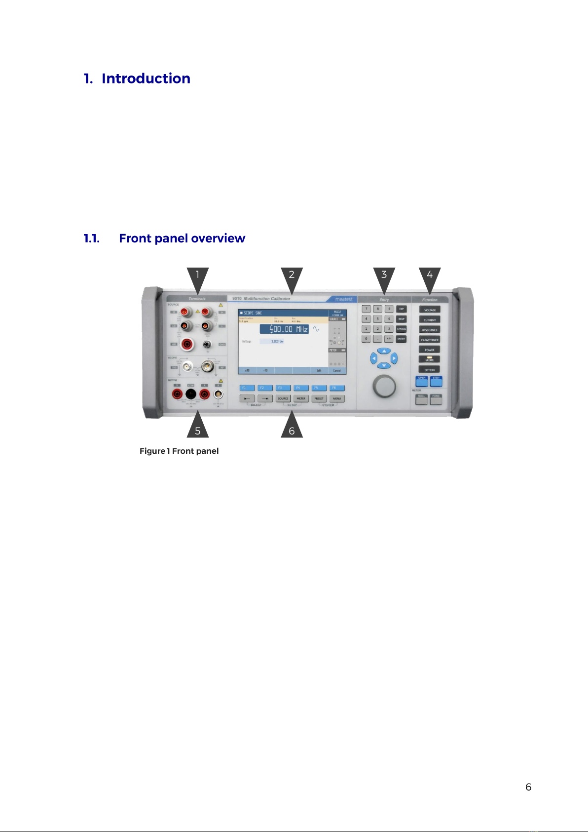
All input and output terminals are located on left side of front panel. Labels between terminals show
overall maximum voltage ratings in standby. Maximum voltage ratings during operation are usually
lower and exceeding them might cause damage to the calibrator! See Specifications for detailed ratings.
1. HI. Outputs set voltage in VOLTAGE and POWER functions, set resistance in 2W mode of
RESISTANCE and CAPACITANCE functions and force signal in 4W RESISTANCE mode.
All signals are relative to LO.
2. I+. Outputs set current in CURRENT and POWER functions and senses RESISTANCE in 4W
mode. All signals are relative to I-.
3. LO. Acts as zero potential in VOLTAGE, POWER, 2W RESISTANCE, 2W CAPACITANCE
and HVR functions. Also provides zero potential to force signal in 4W RESISTANCE mode.
4. I-. Acts as zero potential in CURRENT and POWER functions. Also provides zero potential to
sense signal in 4W RESISTANCE mode. I- terminal is floating up to 20 Vpk relative to the
Ground, SETUP menu allows you to ground this terminal with relay.
5. HIR. Outputs set resistance in HVR function (option HVR).
6. GND. Ground potential, galvanically connected with housing and mains PE wire.
7. TRG. Used as external trigger for SCOPE functions (option SCO).
8. SCO. Outputs all SCOPE function signals through N-type coaxial connector (option SCO).
9. V. Measures voltage and frequency signals in METER function, relative to COM (option MER).
10. R. Connector for 9000-60 Adapter and 91 Cold Junction Compensator only, don‘t connect any
other cables to this terminal! 9000-60 adapter is used for measurement of RTDs and 4W
resistance in METERfunction (optionMER), 91 adapter is used for cold junction compensation
of thermocouples. Adapter terminals are described on the adapters themselves.
11. COM. Acts as zero potential for all METER functions (option MER).
12. A. Measures current signals in METER function, relative to COM (option MER).
Powertek MC9010 User Manual
Display is divided into several sections with following meaning:
1. Selected function. Symbol on the left indicates system status (standby, settling in, ►
running). There may be additional Warning symbols on the right:
a. Warm-up in progress. Calibrator is fully operational but it may be outside
specifications.
b. Overheated. Output terminals cannot be switched on until temperature falls below
safe limit. Set 10V DC and wait a few minutes until the symbol disappears.
c. Other error. Some functions may not be operational and/or outside specifications.
Go to “MENU/Information/Device status” to get detailed information.
2. Tooltip. Shows additionalinformation about selected parameter or main value. Information may
include uncertainty, range, description, limits (burden current, compliance voltage), etc. Tooltip
is hidden when no parameter is selected.
3. Main value. Can be edited via numerical input, cursor keys or rotary knob. Symbol on the right
represents signal shape.
4. Auxiliary parameters. Youcan switch between parameters (and main value) using and
buttons. Every function has different set of auxiliary parameters.
5. Softkey labels. Softkeys below the display change their function dynamically based on current
workspace, these labels describe Softkey functions at any given time.
6. Remote control. Shows active interface and its main parameter.
7. Output status. Indicates output status (grey means OFF, green means ON) and shows diagram
of active output terminals.
8. Input status. Indicates meter status (grey means disconnected, green means measuring) and
shows diagram of active input terminals.
9. Meter reading. Meter function can be changed using FUNC button in METER group.
Powertek MC9010 User Manual
There are 3 button groups in total on the front panel. Softkeys and menu buttons under the display,
function buttons on the right and numeric entry buttons with rotary knob and cursor buttons in between.
1. SELECT. Selects previous/next parameter on display. Selected parameter can be edited and
relevant tooltip is shown (if enabled). Press CANCEL to deselect a parameter.
2. SETUP. Enters/exits device menu. Device menu contains additional function parameters, see
chapter 3.2 or SETUP subchapters in chapter 4 for more details.
3. SYSTEM. Enters/exits main menu. Main menu contains all device-related settings, see menu
structure in chapter 3.
4. Softkeys. Buttons with context-specific functions. Current functions are shown on display, just
above the buttons.
1. Function buttons. Directly selects a calibrator function or toggles function
mode if the function is already selected (f.e. pushing VOLTAGE button in
voltage DC mode switches to voltage AC mode).
2. OPER. Turns output on according to selected function and parameters.
3. STBY. Turns output off.
4. NULL. Sets meter readout to zero by shifting offset of active meter
function.
5. FUNC. Toggles meter function.
Numeric and navigation buttons have dual function. In menus these buttons are used to list throughitems
(and buttons, knob rotation), select an item (ENTER button, OK softkey or knob push), enter a
value or exit menu item (CANCEL button, EXIT/CLOSE softkey).
Outside menus, numeric and navigation buttons are used to edit values of selected parameters. If no
parameter is selected, pressing any numeric or navigation button will select function’s main parameter.
Values can be edited with cursor keys and rotary knob as well. Use and buttons to shift through
digits and and buttons to increment or decrement that digit. Knob rotation works as either / 
or / buttons, knob push toggles between the two modes.
Powertek MC9010 User Manual
There is located power line entry module with power line fuse, power line voltage selector 115/230V
and power line switch. On the bottom side interface connectors RS-232, MSI and optionally LAN, USB
and IEEE488 on the rear panel.
1. Power cord module with power switch, fuse holder and 115/230 V voltage selector
2. RJ-45 (Ethernet) connector for remote control
3. USB connector for remote control
4. GPIB IEEE-488 connector for remote control
5. RS-232 connector
6. External signal synchronization input
7. External signal synchronization output
8. MSI connectors (2x) for control or synchronization with other Meatest devices
9. Fan outlet cover
Every 9010 Multifunction Calibrator delivery includes following items:
- USB stick with user manual 1 pc
- Factory calibration certificate 1 pc
- Power cord (with European E-type plug, feel free to ask for other types when ordering) 1 pc
-Spare fuse (3.15A, 6.3A) 2 pcs
- RS232 cable 1 pc
- Test lead black 1 pc
- Test lead red 1 pc
Following accessory is not part of standard delivery and can be extra ordered:
- Option 91 Pt100 Cold junction compensator
- ISO17025 calibration certificate
Powertek MC9010 User Manual