7
Operating Instructions
2. Using a good grade of light oil,
lubricate the stud, the needle thrust
bearings (2), roller clutch bearing (1)
and needle bearing (1).
MOTOR REPLACEMENT
To replace the motor, refer to Figure 12
and follow the outlined procedures.
Always unplug the
wiring harness
to prevent accidental starting before
attempting to install, service, relocate or
perform any maintenance.
1. Unplug the wiring harness, remove
the two cover rods and the four cover
screws.
2. Gently hand turn the gears of the old
motor back and forth to notice the
backlash (.005). The gears of the new
motor should have the same degree
of play.
3. Loosen the screws on the motor
bands and remove the bands.
4. Disconnect the motor leads, pay
attention to the connections and
remove the motor.
5. Put the new motor in place, taking
care to see that the gears mesh
properly.
6. Fasten the motor band and
connect the new motor leads to the
appropriate lead connections.
7. Check the motor for correct backlash.
The gears should not be too tight
or too loose. Adjust the backlash
by increasing or decreasing the
thickness of the shims between the
motor and motor support rods.
8. Install the cover, two cover rods and
the four cover screws and connect the
wiring harness.
CABLE REPLACEMENT
To replace the cable, follow the outlined
procedures. Use an exact replacement
cable Powerwinch. The winch rating and
cable strength are carefully matched.
Never replace the cable with rope.
Always unplug the
wiring harness
to prevent accidental starting before
attempting to install, service, relocate or
perform any maintenance.
1. Power-out the cable using the remote
control device and unplug the wiring
harness.
2. Remove the two cover rods and the
four cover screws (See Figure 12).
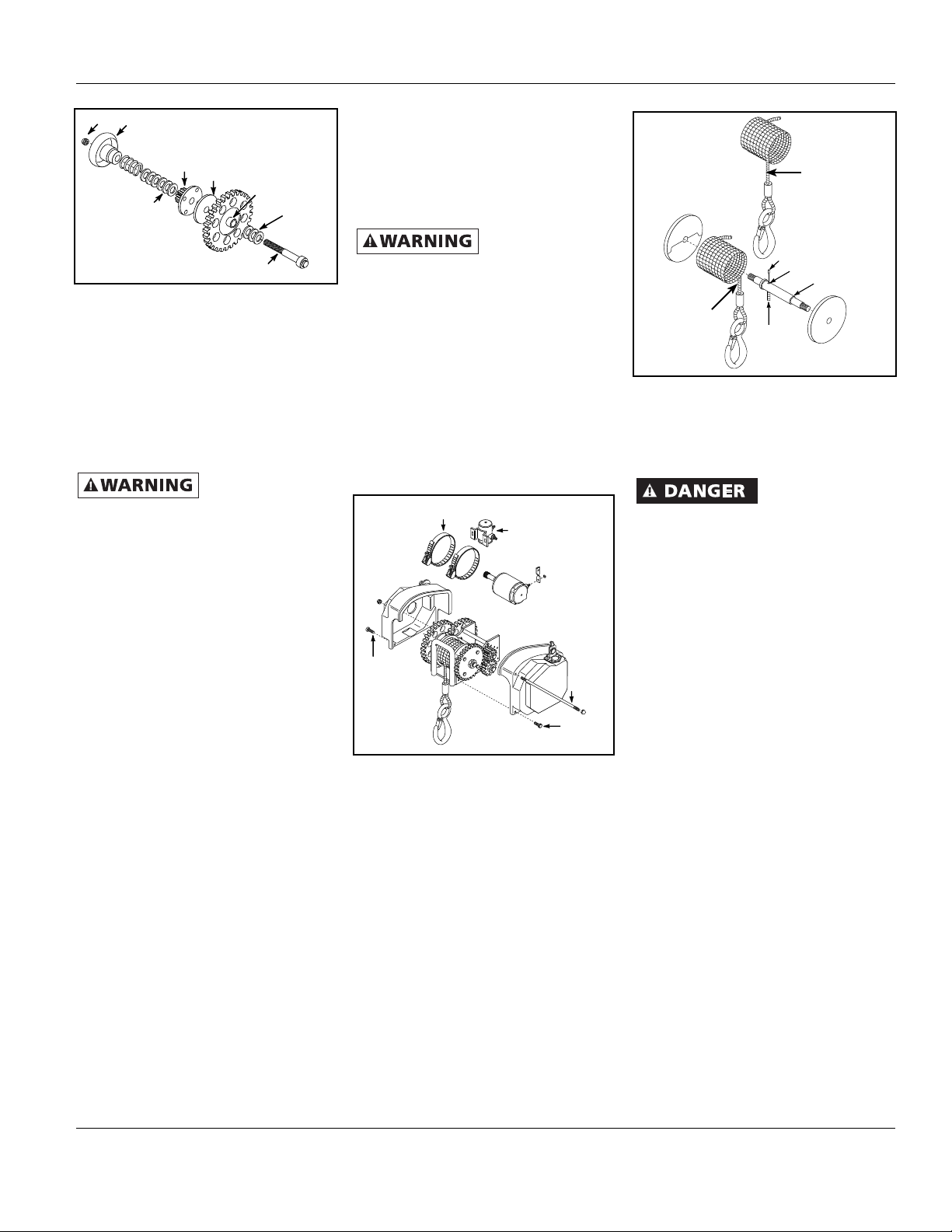
Figure 12 - Motor Replacement
3. Cut the old cable approximately 2”
from the drum and push the remaining
cable and fastener through the drum
to remove (See Figure 13).
4. Insert the new cable into the drum
shaft hole at the end opposite
the counterbored end. Draw the
cable through the hole and out the
counterbored side of the shaft.
5. Push the cable through the fastener
until the cable is flush with the end of
the fastener.
6. Crimp the fastener onto the cable and
pull the cable through the drum shaft
until the fastener seats inside the
counterbore.
Figure 13 - Cable Replacement
7. Install the cover, two cover rods and
the four cover screws and connect the
wiring harness.
8. Power-in the cable with a light load to
help wind the cable straight into the
drum.
The cable fasteners
on this or any winch
are not designed to hold rated loads.
Always leave a minimum of five wraps of
cable on the drum at the bottom layer to
achieve a rated load.
LEVELWIND PLATE
When powering-in the cable, the motor
will continue to run for a few seconds after
releasing the button on the remote control
device, especially without a load. Be sure
to allow for this. Do not let the cable hook
go into the winch and bend the level wind
plate. When winding the cable onto the
drum with no load, keep the cable taut
(tight) going into the drum.
STORAGE
The winch cable must be lubricated
before storing. Lubricate the cable with
Whitmore’s Wire Rope Spray, WD40 or a
similar product. Spray the drum and the
cable as the cable is being wound.
Technical Service
For information regarding the operation,
repair or replacement parts for this
product, please call 1-800-243-3097 for
assistance. Please provide the following
information:
• Model number
• Serial number
• Part number and description
NEEDLE
THRUST
BEARING
CLUTCH
LINING
NEEDLE
BEARING
INSIDE
NEEDLE
THRUST
BEARING
STUD
ROLLER
CLUTCH
BEARING
NUT TRI-MATIC
CONTROL
KNOB
Figure 11 - Tri-Matic Lubrication
MOTOR
BAND
SOLENOID
COVER
ROD
COVER
SCREW
COVER
SCREW
CABLE
FASTENER
COUNTERBORE
CABLE DRUM
INSERT
NEW
CABLE
Models
AP1500
QC1500
QC2500
QC4500
Cable Winds
Over The TOP
Of The Drum
Models
AP3500
QC3500
Cable
Winds
UNDER
The Drum