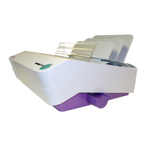
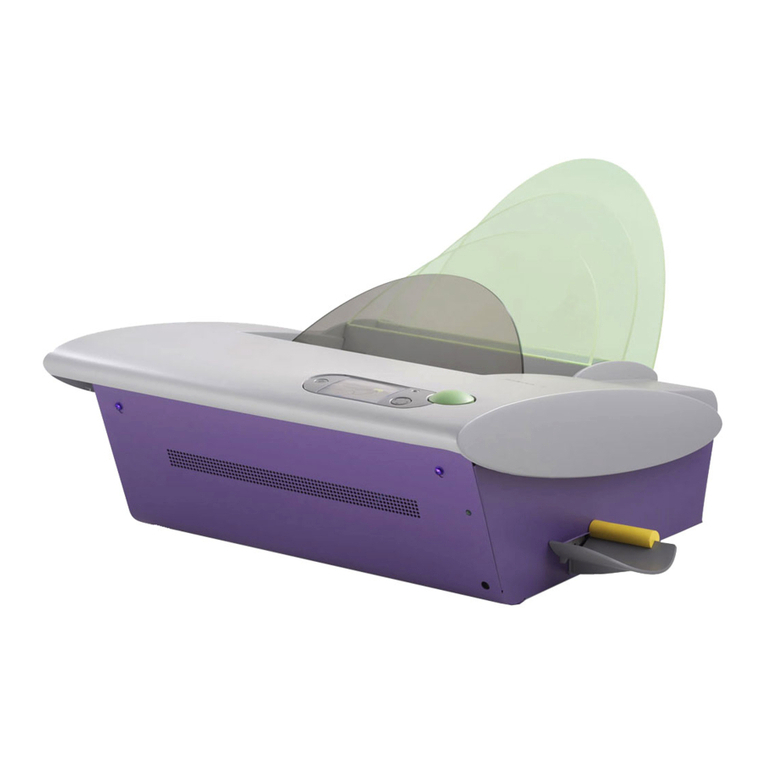
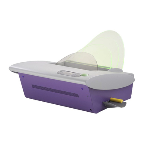
Powis Parker Fastback 8x User manual

MODEL 8x
DOCUMENT BINDER
ServiceManual

ii FB8X Service Manual Rev. C, 9/28/10
COPYRIGHT INFORMATION
Copyright Information
This document contains proprietary and confidential information of Powis Parker Incorporated (“Powis Parker”).
Copyright Powis Parker Incorporated 2004
All Rights Reserved.
No part of this document may be photocopied, reproduced in any form, or translated into another language without prior written
consent of Powis Parker, except as allowed under the copyright laws.
Warranty
The information contained in this document is subject to change without notice.
Powis Parker makes no warranty of any kind with respect to this information. Powis Parker specifically disclaims the implied warranty of
merchantability and fitness for a particular purpose.
PPI shall not be liable for any direct, indirect, incidental, consequential, or other damage alleged in connection with the furnishing or use
of this information.
Notice
Changes are periodically made to this document. Revisions, changes, any technical inaccuracies, and typographical errors will be
corrected in any subsequent editions.

FB8X Service Manual Rev. C, 9/28/10 iii
CONTENTS
1 SUMMARY
2 OVERVIEW
2.1 Main Components of the FB8x
2.2 Diagram of the User Menu
2.3 System Block Diagram
2.4 Specifications
2.5 Bind Media
2.6 Getting the Best Bind Quality
2.7 Contacting Technical Support
3 REQUIRED SERVICE TOOLS
3.1 Hand Tools
3.2 Tools to Service the Heaters
3.3 Tools for Flash Upgrade of the Microcontroller
3.4 Tools needed to inspect the Controller Assembly
3.5 Cleaning Supplies
4 TROUBLESHOOTING
4.1 Power Problems
4.2 Error Messages
4.3 Machine Errors
4.4 Display Problems
4.5 Poor Bind Quality
5 SERVICE MENU
5.1 Accessing the Service Menu
5.2 Diagram of the Service Menu
5.3 Service Menu Descriptions
5.4 Testing and Calibration
5.4.1 Measuring the Heater Temperature
5.4.2 Checking the Sensors
5.4.3 Calibrating the Sensors, the Switches, and the Carriage Assembly
5.4.4 Entering the A_HI/A_LO values
5.4.5 Checking Motor Functions
5.4.6 Checking the Resistance of the Heater Sensors
5.4.7 Checking the Resistance of the Heater Power Connectors

iv FB8X Service Manual Rev. C, 9/28/10
6 SERVICE AND CALIBRATION PROCEDURES
(This section contains detailed procedures for removing and installing the specified component on the FB8x)
6.1 Covers
6.1.1 Left Cover
6.1.2 Right Cover
6.1.3 Front Cover
6.2 Cooling Rack
6.3 Controller Assembly
6.3.1 Inspecting the Controller Assembly
6.3.2 Removing and Installing the Controller Assembly
6.3.3 Changing the Fuses
6.4 Carriage Drive
6.5 Bender Drive
6.6 Sensors
6.6.1 Strip Present PCA
6.6.2 Book Emitter PCA
6.6.3 Book Detector PCA
6.7 Switches
6.7.1 Carriage Home Switch
6.7.2 Carriage Clamp Switch
6.8 Display
6.9 Heater Assemblies
6.9.1 Bender Assembly
6.9.2 Carriage Assembly (Back Heater)
6.9.3 Spine Assembly
6.10 Fan
6.11 Jaw Assembly
6.12 Replacing Grip Tape
7 UPGRADING FIRMWARE
7.1 Tools Required
7.2 Upgrading Firmware Procedure
8 SERVICE KIT PART NUMBERS
9 SERVICE KIT PICTURES
10 PICTURES OF FB8x PARTIALLY EXPLODED
CONTENTS

FB8X Service Manual Rev. C, 9/28/10 Page 1
SUMMARY
1
The newly redesigned Fastback Model 8x makes service and repair
easier than ever. While in outward appearance it looks very similar
to its predecessor, the Model 8 binder, you will find that beneath the
covers the binder has been dramatically simplified and improved. This
manual will guide you through the various routines needed to service
this machine. It will provide you with diagrams of the User Menu,
Service Menu, and Electrical Connectivity, as well as a complete list
of Service Parts and pictures of the machine partially exploded. This
manual will introduce you to the Service Menu and various functions
to test Heaters, Sensors, and Mechanisms. It will guide you through
the process of upgrading the Firmware using your computer. The
manual will provide you with a troubleshooting chart to quickly and
accurately diagnose and solve common problems, and it will tell you
how to perform routine service procedures, and how to disassemble
and reassemble the machine correctly and efficiently. In all, this
manual will tell you everything you need to know to keep the machine
binding and the customer happy.
The process by which the Model 8x binds documents has not
changed. The Model 8x has three heaters located in the binding
recess that heat the adhesive coating on the Lx-Strip or the spine on
the Halfback Cover, and adhere it to the spine, front, and back of the
document. These three heaters are called the Bender Heater, the
Spine Heater, and the Back Heater. They have been upgraded from
the previous versions with additional temperature sensing elements
that will allow the heaters to better regulate temperature.
The Model 8x binder has two sensors, the Book Sensor and the
Strip Sensor, designed to detect the presence of the document and
the strip when they are inserted in the binding recess. While the
Book Sensor determines only the presence of the book, the Strip
Sensor will sense the presence of a strip and determine whether you
are using the correct width strip for the document you are binding.
The binder is also equipped with encoders and switches that
determine the thickness of the document you are binding and the
pressure the Carriage Assembly must clamp the document to achieve
the best possible bind without overexerting the motors or any of the
other mechanical parts.
After giving the new Model 8x a few test binds you will find that the
improvements made to the binder will provide the customer and the
service technician with a machine that is both easy to use and easy to
service.
Page 2 FB8X Service Manual Rev. C, 9/28/10
Left Side Cover
Cooling Rack
Right Side Cover
Front Cover
Jaw Spring
Right Bender Pivot
Bender Gear
LCD Display
Carriage Drive Assembly
Carriage Home Switch
Spine Spring
Left Carriage Guide
Jaw Guide
Carriage Alignment Plate
OVERVIEW- Main Components
2.1 MAIN COMPONENTS OF THE FB8x
2
(Binder with Book Fences removed.)
Carriage Spring
Bender Link
Assembly
Jaw Guide
Jaw Spring
Tamping Platform
Book Sense Detector PCA
(located inside the Carriage Assembly)
Left Bender Pivot

FB8X Service Manual Rev. C, 9/28/10 Page 3
Book Sense Emitter PCA
Bender Motor
Assembly
OVERVIEW- Main Components
2.1 MAIN COMPONENTS OF THE FB8x
Strip Detector PCA
Bender Heater
2
(Picture shows Tamping Platform partially removed.)

Page 4 FB8X Service Manual Rev. C, 9/28/10
OVERVIEW- Main Components
2
2.1 MAIN COMPONENTS OF THE FB8x
Carriage Clamp Switch
Carriage Spring
Spine Heater
Cooling Platen
Carriage Assembly
(Back Heater)
(Picture shows Cooling Rack and Left Cover removed.)

FB8X Service Manual Rev. C, 9/28/10 Page 5
Fuses
Transformer
Serial Port
Microcontroller
Power Entry Module
2.1 MAIN COMPONENTS OF THE FB8x
CONTROLLER ASSEMBLY
J10 J8 J11 J2 J3 J1 J4
J5
J6
J7
J1 Spine Heater Temp Sensor Connector
J2 Bender Heater Temp Sensor Connector
J3 Back Heater Temp Sensor Connector
J4 Motors Connector
J5 Spine Heater Power Connector
J6 Bender Heater Power Connector
J7 Back Heater Power Connector
J8 Motors and Carriage Sensors Connector
J10 LCD Connector
OVERVIEW- Main Components
2
Strip Present Emitter

Page 6 FB8X Service Manual Rev. C, 9/28/10
OVERVIEW- User Menu
2
2.2 User Menu
USER MENU
L-STRIP
SPINE BIND TIME
LANGUAGE
STRIP MODE
COVER BIND TIME
HALFBACK
PERFECTBACK LF
PERFECTBACK PS
EDIT MODE
SETTINGS
L-STRIP ON
L-STRIP OFF
-1 SECONDS
+0 SECONDS
+1 SECONDS
+2 SECONDS
+3 SECONDS
+4 SECONDS
-5 SECONDS
+0 SECONDS
+5 SECONDS
+10 SECONDS
+15 SECONDS
+20 SECONDS
-2 SECONDS
+5 SECONDS
DUTCH
DEUTSCH
FRANCAIS
ITALIANO
ESPAÑOL
NORSK
ENGLISH
SVENSKA
DANSK
SETTING LANGUAGE:
WRAPAROUND, NO "EXIT"
OPTION
SETTING SPINE BIND TIME:
NO WRAPAROUND, NO "EXIT"
OPTION
SETTING COVER BIND TIME:
NO WRAPAROUND, NO "EXIT"
OPTION
This item is present only
if the STRIP MODE is
"L-STRIP ON"
Lx-STRIP
Lx-COMP STRIP
EXIT
EXIT
EXIT

FB8X Service Manual Rev. C, 9/28/10 Page 7
OVERVIEW- System Block Diagram
2
2.3 System Block Diagram

Page 8 FB8X Service Manual Rev. C, 9/28/10
OVERVIEW- Specifications
2
Power Requirements: FB8x: 115V (110-125VAC) 50-60 Hz, 8.4 Amps
FB8xE & FB8xA: 230V (220-240VAC) 50-60 Hz, 4.2 Amps
FB8xJ: 100V (90-110VAC) 50-60 Hz, 9.5 Amps
Power Consumption: FB8x: 950 Watts while binding, 55 Watts standby
FB8xE & FB8xA: 950 Watts while binding, 55 Watts standby
FB8xJ: 950 Watts while binding, 55 Watts standby
Recommended Operating
Temperature and
Humidity:
15 to 35 degrees (C), 59 to 95 degrees (F)
Humidity Range: 5 to 80% RH non condensing
Weight: 17 lbs
Dimensions: With book fences attached: 19.3” W x 11.1” H x 12.5” D
Without book fences attached: 19.3” W x 6.0” H x 10.6” D
Bind Capacity: Lx-Strip .04” to 1.0” (1 mm to 25 mm), about 10-250 sheets.
10-125 sheets = Narrow Lx-Strip
126-250 sheets = Medium Lx-Strip
L-Strip .04” to 0.7” (1 mm to 18 mm), about 10-175 sheets.
10-80 sheets = Narrow L-Strip
81-175 sheets = Medium L-Strip
Not compatible with Wide L-Strip.
Halfback covers .04” to 0.8” (1 mm to 20 mm), about 10-200 sheets.
10-100 sheets = Narrow Halfback
101-200 sheets = Medium Halfback
Does not work with Wide Halfback Covers.
Perfectback Strips .04” to 1.0” (1 mm to 25 mm), about 10-250 sheets.
10-125 sheets = Narrow Perfectback Lx-Strip
126-250 sheets = Medium Perfectback Lx-Strip
Duty Cycle: 500 binds per month average
Bind Speed: 35-55 seconds
Safety Certications: UL60950
IEC60950/EN60950
2.4 Specifications

FB8X Service Manual Rev. C, 9/28/10 Page 9
OVERVIEW- Bind Media
2
The newly redesigned Model 8x Binder is capable of binding the following strips:
Lx-Strip
Lx-Comp Strip
L-Strip (Narrow and Medium only)
Halfback Covers (Narrow and Medium only)
Perfectback®PS Strips
Perfectback®LF Strips
Selecting the Binding Mode
To bind with any of these various binding strips, enter the User Menu and select the
binding strip you wish to bind with.
Bind Memory
When the machine is turned off and on, the last bind setting will be retained.
Binding Widths
The Model 8x binder is not compatible with wide L Strips or wide Halfback Covers.
(See 2.5 Specifications).
Binding Hard Cover Books
Use Lx-Strip or L-Strip to bind book blocks to be made into Hard Cover Books.
2.5 Bind Media

Page 10 FB8X Service Manual Rev. C, 9/28/10
OVERVIEW- Getting the Best Bind Quality
2
2.6 Getting the Best Bind Quality
• Before binding, make sure the binder is set in the correct binding mode.
• Before placing the strip into the binding recess, fold the strip in 90° angle making
sure the adhesive side faces inward.
• Place the strip into the binding recess with the adhesive side facing up. The short
side of the bent “L” should be resting against the back wall. Slide the strip all the
way to the right of the machine.
• Before binding, tap the pages several times to ensure that they are even when the
document is in the binding recess. The right edge of the strip and right edge of the
document should line up and be justified against the right side of the binding recess.
• The grain of the paper should run parallel to the binding edge of the document. All
paper has a grain — it is a result of the fibers that make up the paper. If the grain
runs parallel to the long side of the sheet, the paper is “grain long”. When the grain
runs parallel to the short side of the paper, it is “grain short”.
A sheet of paper will naturally flex more easily along the direction of its grain. Try
it and see. (Hold a piece of paper the long way lightly in your fingertips and gently
bow the paper, allowing it to flex. Now try it the other way. See the difference?
Most copy papers are grain long, so you should not have any problems with the
bind. Grain long paper will give you the best bind. Occasionally you may find papers
that are grain short, so we recommend you test unfamiliar papers before binding
large numbers of documents.
• Coated papers, and papers with heavy ink or toner coverage may also experience
problems with binding. If you have documents with heavy ink or toner coverage,
always do a test bind first to ensure that your documents will bind properly.
• After the binding cycle, be sure to place your document entirely upright, with the
bound side down, against one of the two rear book support fences for five minutes.
Improper cooling of your document may result in a crooked spine. Bind strength
reaches the maximum strength after 24 hours.
• NOTE: When placing multiple documents on the Cooling Rack, make sure it
doesn’t get overloaded to where the front document hangs off the metal step.
MAINTENANCE TIP : Minor glue buildup on the heaters is expected. When
cleaning the heaters, turn the machine off and unplug it. Wait for the heaters to
cool, and then wipe off any glue using a clean dry lint free cloth. Cleaning solution is
not necessary.
(Caution: The heaters are very delicate. Do not use anything sharp to remove glue
from the clamps, platen, or interior surfaces of the binder. )

FB8X Service Manual Rev. C, 9/28/10 Page 11
OVERVIEW- Technical Assistance
2
If there are any questions not answered in this manual, please contact the
Powis Parker Technical Support Dept: 510-848-2463.
2.7 Contacting Technical Support

Page 12 FB8X Service Manual Rev. C, 9/28/10
OVERVIEW
2
THIS PAGE IS INTENTIONALLY LEFT BLANK

FB8X Service Manual Rev. C, 9/28/10 Page 13
REQUIRED SERVICE TOOLS
3
When servicing a Model 8x binder the following tools are required:
3.1 HAND TOOLS
Phillips Screwdrivers #1 and #2
Needle Nosed Pliers
Diagonal Cutters
Fuse Puller
2.5mm Hex Key
Pen
Exacto Knife
3.2 TOOLS TO SERVICE THE HEATERS
Temperature Meter (K-820-011)
Straight Temperature Probe (K-820-012)
Right Angle Temperature Probe (K-820-3436)
Ohmmeter
3.3 TOOLS FOR FLASH UPGRADE OF FIRMWARE
P31 Printer Cable (K-551-1685)
PC with either Windows 98, 2000, XP, or ME, and a 9-pin com port
Internet Access
3.4 TOOLS NEEDED TO INSPECT THE CONTROLLER ASSEMBLY
Ground Strap
3.5 CLEANING SUPPLIES
Citrus Cleaning Solution (K-212-001)
Lint Free Cloth

Page 14 FB8X Service Manual Rev. C, 9/28/10
TROUBLESHOOTING GUIDE
4
4.1 Power Problems
Possible Cause Solution
Power Cord is not securely plugged in. Check that the Power Cord is securely plugged into the
machine and into the outlet in the wall.
Electrical outlet is not functioning. Plug the machine into another electrical outlet.
Machine is plugged into the wrong voltage outlet. Use the correct voltage outlet to power the machine.
Wire Harness connections are loose. Check that all wire connectors are securely
plugged into the Controller Assembly.
Blown Fuse. Check fuses on the Controller Assembly and
replace if any are blown.
Failed Controller Assembly. Replace the Controller Assembly.
• NO POWER
Possible Cause Solution
A 230v machine in plugged into a 115v outlet. Plug the machine into a 230v outlet.
Failed Controller Assembly. Replace the Controller Assembly.
• POWER FLICKERS ON AND OFF
Possible Cause Solution
A 230v machine in plugged into a 115v outlet. Plug the machine into a 230v outlet.
See the “NO POWER” troubleshooting table above.
• BACKLIGHT COMES ON, NOTHING ELSE HAPPENS
Possible Cause Solution
A problem with the display. See troubleshooting section 4.4 “Display Problems”.
• WHEN TURNED ON, THE MOTORS MOVE BUT NOTHING IS ON THE DISPLAY
Possible Cause Solution
Short circuit in heaters. Check the resistance of the Heaters. See Section
5.4.7 “Checking the Resistance of the Heater Power
Connectors”.
Short in the Controller Assembly. If none of the heaters have shorted out, the
problem lies in the Controller Assembly. Replace
the Controller Assembly.
• FUSES BLOW REPEATEDLY

FB8X Service Manual Rev. C, 9/28/10 Page 15
TROUBLESHOOTING GUIDE
4
Possible Cause Solution
The operator pressed the Bind button without inserting a
book into the binding recess.
Place a book into the machine and then press the Bind
button.
The sheets are not fully justified against the right side of the
binding recess.
Tap the edges of the sheets until the book is flush
against the right side of the binding recess prior to
pressing the BIND button.
The Book Sensor is damaged. Replace the Book Sensor.
Failed Controller. Replace the Controller
• Error Message:“INSERT BOOK”
Possible Cause Solution
You are trying to bind too many sheets with the medium strip. Remove some sheets.
Possible Cause Solution
You are trying to bind too many sheets with a narrow strip. Remove some sheets or use a medium width strip.
There is no strip in the binding recess. Insert a medium strip.
Possible Cause Solution
You are trying to bind too few sheets with a medium strip. Add some sheets or use a narrow width strip.
There is no strip in the binding recess. Insert a narrow strip.
Possible Cause Solution
The strip is inserted into the machine backwards. Make sure the short end of the strip is vertical and the
long end of the strip is flat.
Make sure the strip is flat. An over folded or curled strip
can cause a “Reverse Strip” error.
Possible Cause Solution
The strip is too wide for the amount of sheets placed in the
binding recess.
Add more sheets or use a narrower width strip.
The strip is not folded. Make sure to fully fold the strip into a 90 degree angle.
The strip is not lined up properly. Make sure the strip and the sheets are justified against
the back of the binding recess.
The machine is configured to bind the new Lx-Strip and
you tried to bind using the original type L-Strip.
In settings, select the L-STRIP ON menu option in the
STRIP MODE Settings menu.
• Error Message:“USE SMALLER SIZE”
• Error Message:“BOOK TOO THICK”
• Error Message:“USE MEDIUM SIZE”
• Error Message:“USE NARROW SIZE”
• Error Message:“REVERSE STRIP”
4.2 Error Messages

Page 16 FB8X Service Manual Rev. C, 9/28/10
TROUBLESHOOTING GUIDE
4
4.3 Machine Errors
Possible Cause Solution
Heater sensor leads are not plugged in correctly. Check that the connectors J1, J2, and J3 are plugged in
correctly.
Heater sensor malfunction. Check the resistance of the Heaters. See Section 5.4.6
“Checking the Resistance of the Heater Sensors”.
Machine is extremely cold. The FB8x is not designed to function below 0°C/32°F.
Failed Controller Assembly. Replace the Controller Assembly.
• Error Message: MACHINE ERROR 11, 21, or 31
This error indicates an under-temp error in one of the heaters.
Possible Cause Solution
Heater sensor leads are not plugged in correctly. Check that the connectors J1, J2, and J3 are plugged in
correctly.
Heater sensor malfunction. Check the resistance of the Heaters. See Section 5.4.6
“Checking the Resistance of the Heater Sensors”.
Heater calibration is inaccurate. Recalibrate the heaters. See Section 5.3.2 “Cal Heaters”.
Heater A_HI/A_LO INPUT values are incorrect. Verify the A_HI/A_LO values on the heater tags match
the values in the A_HI/A_LO INPUT menu. See section
5.4.4.
Failed Controller Assembly. Replace the Controller Assembly.
• Error Message: MACHINE ERROR 12, 15, 22, 25, 32, or 35
This error indicates an over-temp error in one of the heaters.
Possible Cause Solution
Heater calibration is inaccurate. Recalibrate the heaters. See Section 5.3.2 “Cal Heaters”.
Heater A_HI/A_LO INPUT values are incorrect. Verify the A_HI/A_LO values on the heater tags match
the values in the A_HI/A_LO INPUT menu. See section
5.4.4.
Failed Controller Assembly. Replace the Controller Assembly.
• Error Message: MACHINE ERROR 13, 14, 23, 24, 33, or 34
This error indicates a problem with the heater temperature settings.
Other manuals for Fastback 8x
1
Table of contents
Other Powis Parker Binding Machine manuals

Powis Parker
Powis Parker FastBack Model 11 User manual

Powis Parker
Powis Parker FastBack 11 User manual

Powis Parker
Powis Parker Fastback 8x User manual

Powis Parker
Powis Parker Fastback Hardcover User manual

Powis Parker
Powis Parker FASTBACK 15 User manual

Powis Parker
Powis Parker Fastback 20 User manual

Powis Parker
Powis Parker FASTBACK 15 User manual