PowMr POW-LVM5K-48V-N User manual

1

1
Important Safety Instructions
Please save these instructions for future use!
This manual contains all safety, installation and operating instructions for the POW-LVM5K Series
all-in-one solar charge inverter.
Please read all instructions and precautions in the manual carefully before installation and
use.
⚫Non-safety voltage exists inside the all-in-one solar charge inverter. To avoid personal injury,
users shall not disassemble the all-in-one solar charge inverter themselves. Contact our
professional maintenance personnel if there is a need for repair.
⚫Do not place the all-in-one solar charge inverter within the reach of children.
⚫Do not install the all-in-one solar charge inverter in harsh environments such as moist, oily,
flammable or explosive, or heavily dusty areas.
⚫The mains input and AC output are high voltage, so please do not touch the wiring terminals.
⚫The housing of the all-in-one solar charge inverter is hot when it is working. Do not touch it.
⚫Do not open the terminal protective cover when the all-in-one solar charge inverter is working.
⚫It is recommended to attach proper fuse or circuit breaker to the outside of the all-in-one solar
charge inverter.
⚫Always disconnect the fuse or circuit breaker near the terminals of PV array, mains and battery
before installing and adjusting the wiring of the all-in-one solar charge inverter.
⚫After installation, check that all wire connections are tight to avoid heat accumulation due to poor
connection, which is dangerous.
⚫The all-in-one solar charge inverter is off-grid. It is necessary to confirm that it is the only input
device for load, and it is forbidden to use it in parallel with other input AC power to avoid
damage.

2
Features
Important Safety Instructions....................................................................................................... 1
Production Instructions................................................................................................................ 4
Features ................................................................................................................................. 2
Basic System Introduction....................................................................................................... 6
Production Overview............................................................................................................... 7
Dimension Drawing................................................................................................................. 8
Installation..................................................................................................................................... 9
Installation Notice ................................................................................................................... 9
Select the Mount Location..................................................................................................... 10
Mount the Inverter................................................................................................................. 10
Preparation............................................................................................................................11
Connection .................................................................................................................................. 12
Wiring Specification and Breaker Type.................................................................................. 12
AC Input/Output Wiring ......................................................................................................... 13
PV Input Wiring..................................................................................................................... 14
Battery Wiring....................................................................................................................... 15
Final Assembly..................................................................................................................... 16
Start up the inverter ............................................................................................................. 16
Operating Mode........................................................................................................................... 17
Charge Mode........................................................................................................................ 17
Output Mode......................................................................................................................... 18
Operation Instruction.................................................................................................................. 19
Operation and Display Panel ................................................................................................ 19
Introduction to LCD screen ................................................................................................... 20
Real-time Data View Method ................................................................................................ 22
Setting Parameter................................................................................................................. 23
Battery Type Parameters ...................................................................................................... 31
Other Function ............................................................................................................................ 33
Dry Node Function................................................................................................................ 33
RS485 Communication Function........................................................................................... 33
Table of Contents

3
USB Communication Function .............................................................................................. 33
Protection.................................................................................................................................... 34
Protection Function............................................................................................................... 34
Meaning of Fault Code.......................................................................................................... 35
Troubleshooting .................................................................................................................... 37
System Maintenance................................................................................................................... 38
Technical Parameter ................................................................................................................... 39

4
Production Instructions
POW-LVM5K series is a new type of mixed solar energy storage inverting & control all-in-one
inverter integrating solar energy storage & municipal power charge storage and AC sine wave
output. It adopts DSP control and advanced control algorithm to achieve characteristics of high
response speed, high reliability and high industrial standard. There are four charge modes namely
only solar power, mains power priority, solar power priority, mains power & solar power; and two
optional output modes, namely inverting and mains power to meet different application needs.
The solar charge module adopts the latest optimized MPPT tracking technology, which can quickly
track the maximum power point of the photovoltaic array in any environment to obtain the maximum
energy of the solar panel in real time with wide voltage range of MPPT.
AC-DC charge module adopts advanced control algorithm to realize full digital double closed-loop
control of voltage and current, with high control accuracy and small volume. Battery can be charged
and protected stably and reliably with wide AC voltage input range, full input/output protection
function.
DC-AC inverter module based on full digital intelligent design adopts advanced SPWM technology,
outputs pure sine wave, converts DC into AC. It is suitable for AC loads such as household
appliances, electric tools, industrial device, electronic audiovisual, etc. The product adopts the
segment LCD display design to display the operation data and state of the system in real time. The
comprehensive electronic protection function ensures that safety and stability of the whole system.
Production Instructions

5
⚫Adopt full digital voltage and current double closed-loop control and advanced SPWM
technology to output pure sine wave.
⚫Two output modes, i.e. mains bypass and inverter output can achieve uninterrupted power
supply function.
⚫Four optional charge modes: only solar energy, mains priority, solar energy priority and mixed
charge.
⚫Advanced MPPT technology, with efficiency up to 99.9%.
⚫Wide MPPT voltage range.
⚫With function of activating lithium battery with solar energy and AC mains power, it supports
connection of lead-acid battery and lithium battery.
⚫LCD screen design and 3 LED indicator lights dynamically display system data and operation
states.
⚫ON/OFF rocker switch can control AC output.
⚫With power saving mode function, it can reduce no-load loss.
⚫Intelligent adjustable speed fan is adopted for efficient heat dissipation and extended system life.
⚫Possessing multiple protection functions and 360°comprehensive protection.
⚫Possessing complete short circuit protection, overvoltage and undervoltage protection, overload
protection, back filling protection, etc.
⚫It has the function of mixed load: when the battery is not connected, photovoltaic and
commercial power can supply power to the load at the same time (if there is no battery, the
commercial power must be connected). When the battery is full, it can also enter the mixed load
mode, which can make full use of the photovoltaic energy.

6
Basic System Introduction
The figure below shows the system application scenario of this product. A complete system
includes the following parts:
1. Photovoltaic module: Convert the light energy into direct current energy and then charge the
battery via the all-in-one inverter, or directly invert the light energy into alternating current to supply
power to the load.
2. Mains or generator: Connected at the AC input, it can supply power to the load and charge the
battery at the same time. If no mains power or generator is connected, the system can also operate
normally. At this time, the load power is supplied by the battery and photovoltaic modules.
3. Battery: The battery is to ensure the normal power consumption of the system load in case of no
sufficient solar energy or mains supply.
4. Household load: It can be connected to various household and office loads, including AC loads
such as refrigerators, lamps, televisions, fans, air conditioners, etc.
5. Inverting and control all-in-one inverter: The energy conversion device of the whole system.
The specific system wiring mode is determined by the actual application scenario.

7
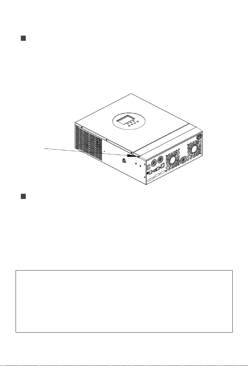
Production Overview
Overload protector
⑨
Dry contact port
②
ON/OFF rocker switch
⑩
Cooling fan
③
AC input port
⑪
Battery port
④
AC output port
⑫
Cooling fan
⑤
Grounding screw hold
⑬
PV port
⑥
RS485-2 communication port
⑭
Touch the key lightly
⑦
USB communication port
⑮
Indicator light
⑧
RS485-1 communication port
⑯
LCD screen

8
Dimension Drawing

9
Installation
Installation Notice
Before installation, please carefully read the manual and get familiar with the installation step.
⚫Take care while installing the battery. When installing the lead-acid liquid battery, it is required to
wear goggles. Any body part contacting the battery acid must be washed with clear water in
time.
⚫Don ‘t place any metal object beside the battery to prevent short circuit of the battery.
⚫Acid gas may be generated during battery charge. Therefore, it is required to ensure good
ventilation around the environment.
⚫During cabinet installation, sufficient space shall be reserved around the all-in-one inverter for
heat dissipation; do not install the all-in-one inverter and lead-acid liquid battery in the same
cabinet to avoid the corrosion of the all-in-one inverter by acid gas generated during battery
operation.
⚫Only the battery with type consistent with the all-in-one inverter can be charged.
⚫Loose connection points and corroded wires may cause great heat, thereby melting the
insulation layer of wires, burning the surrounding materials, or even causing fire. Therefore, all
connectors must be tightened, and the wires must be fixed with ties, so as to avoid the
looseness of connectors caused by wire shaking during mobile application.
⚫Tie conductors are selected based on no greater than 5A/mm2current density.
⚫The machine installed outdoors shall be protected against direct sunlight and rain.
⚫After the power switch is turned off, there is still high voltage inside the all-in-one inverter.
Please do not open or touch the internal components, and carry out relevant operation after the
capacitor is fully discharged.
⚫Please do not install the all-in-one inverter in a humid, greasy, flammable, explosive or dusty or
other severe environments.
⚫The polarity of the battery input end of this product shall not be reversed, otherwise the device
may be damaged easily or there may be some unpredictable dangers.
⚫AC supply input and AC output are both high voltage, so please do not touch the wires.
⚫Do not touch the fan in working to prevent injury.
⚫It is required to confirm that the all-in-one inverter is the unique power supply input device for the
load device. It is forbidden to use the machine in parallel with other input AC power to avoid
damage.
Installation
10
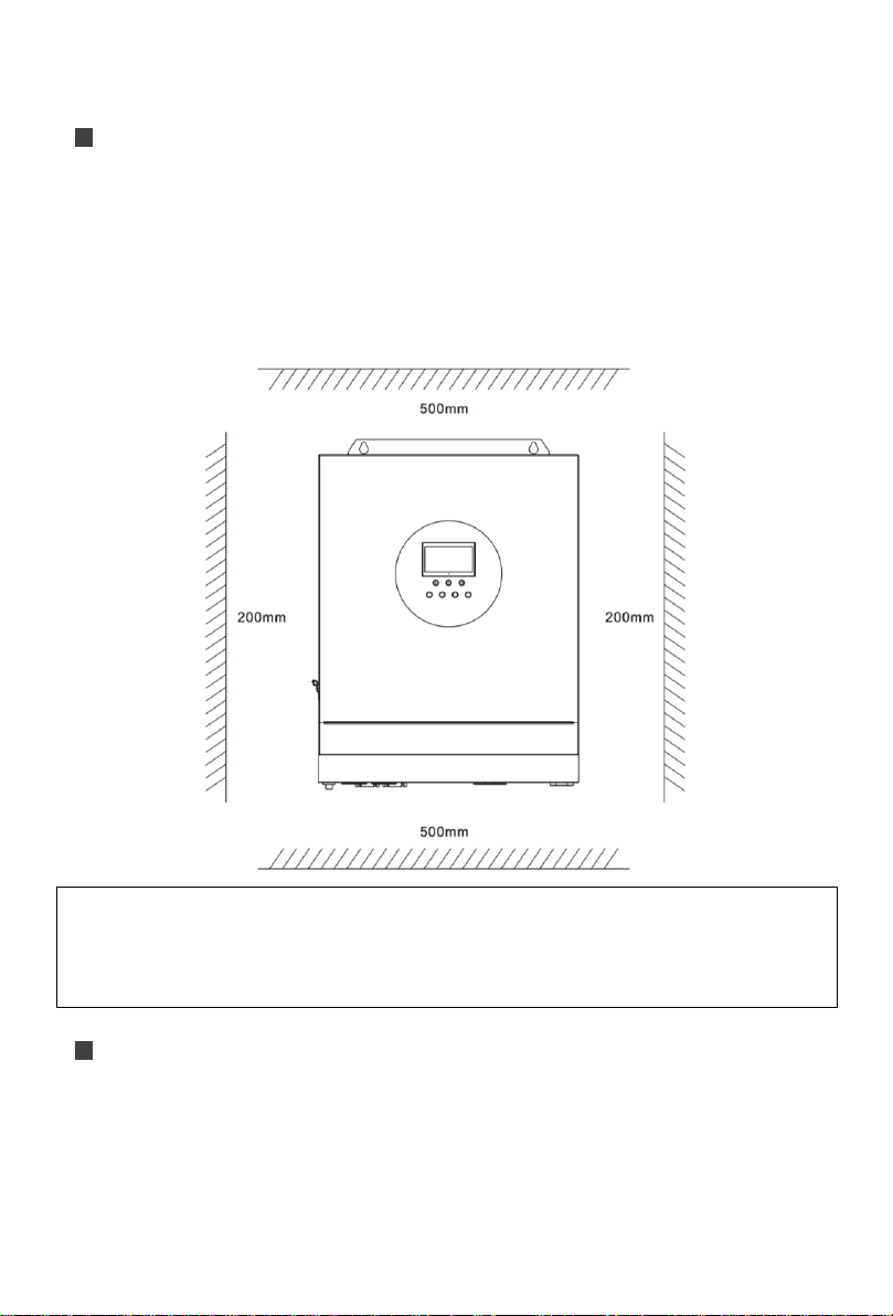
Select the Mount Location
⚫Confirm the installation position and heat dissipation space, confirm the installation position of all-
in-one inverter, such as wall surface;
⚫To install the all-in-one inverter, guarantee there is sufficient air flowing through the cooling fins of
all-in-one inverter. At least reserve 200mm space at the left and right air outlets of the all-in-one
inverter to guarantee heat loss through natural convection. Refer to the overall installation
schematic as shown below.
Mount the Inverter
Install the unit by screwing two screws. It’s recommended to use M6 screws.
WARNING
⚫Danger of explosion! Never install the all-in-one inverter and lead-acid liquid battery into a
same sealed space or in a sealed place with probable accumulation of battery gas.
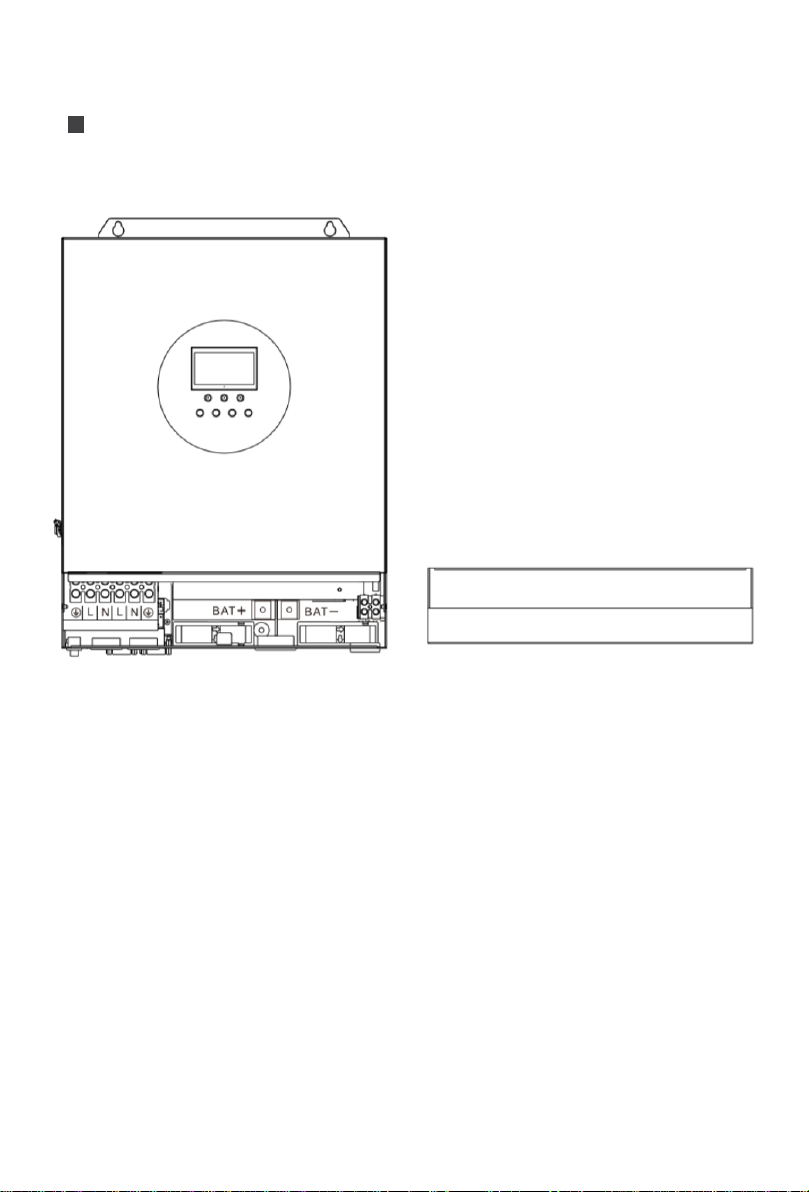
11
Preparation
Before connecting all wirings, please take off bottom cover by removing two screws as shown
below.

12
Connection
Wiring Specification and Breaker Type
For wiring and installation ways, it is required to observe national and local electrical specification
requirements.
Recommended wiring specification and breaker type for photovoltaic array: The output current of
the photovoltaic array is affected by the form, connection way and illumination angle of photovoltaic
array, therefore the minimum wire diameter of the photovoltaic array is calculated based on the
short circuit current of photovoltaic array. Please refer to the short circuit current value in the
specification of photovoltaic array (the short circuit current keeps unchanged for the photovoltaic
arrays in series connection; the short circuit current of photovoltaic arrays in parallel connection is
the sum of short circuit current of all components connected in parallel); the short circuit current of
the array cannot exceed maximum input current of PV.
➢Please refer to the table below for PV input wire diameter and switch:
Model
Wire Diameter
Max. PV input current
Circuit breaker Spec
POW-LVM5K-48V-N
6mm2 /10AWG
22A
2P—25A
Note: The voltage in series shall not exceed maximum PV input open-circuit voltage.
➢Please refer to the table below for recommended AC input wire diameter and switch:
Model
Wire Diameter
Max. bypass input
current
Circuit breaker Spec
POW-LVM5K-48V-N
10mm2 /7AWG
63A
2P—63A
Note: There is already a corresponding breaker at inputconnection point of mains supply. Therefore,
it is not necessary to add one more.
➢Recommended input wire diameter and switch type for battery
Model
Wire
Diameter
Rated Battery
Discharge Current
Max. Charge
Current
Circuit Breaker
Spec
POW-LVM5K-
48V-N
30mm2 /7AWG
125A
80A
2P—200A
➢Recommended wire specification and breaker type for AC output
Model
Wire diameter
Rated Inverter AC
Output current
Max. bypass
output current
Circuit Breaker
Spec
POW-LVM5K-
48V-N
10mm2 /7AWG
42A
63A
2P—63A
Note: The wire diameter is only for reference. In case of long distance between photovoltaic array
Connection

13
and all-in-one inverter or between all-in-one inverter and battery, use thicker wire to reduce voltage
drop and improve system performance.
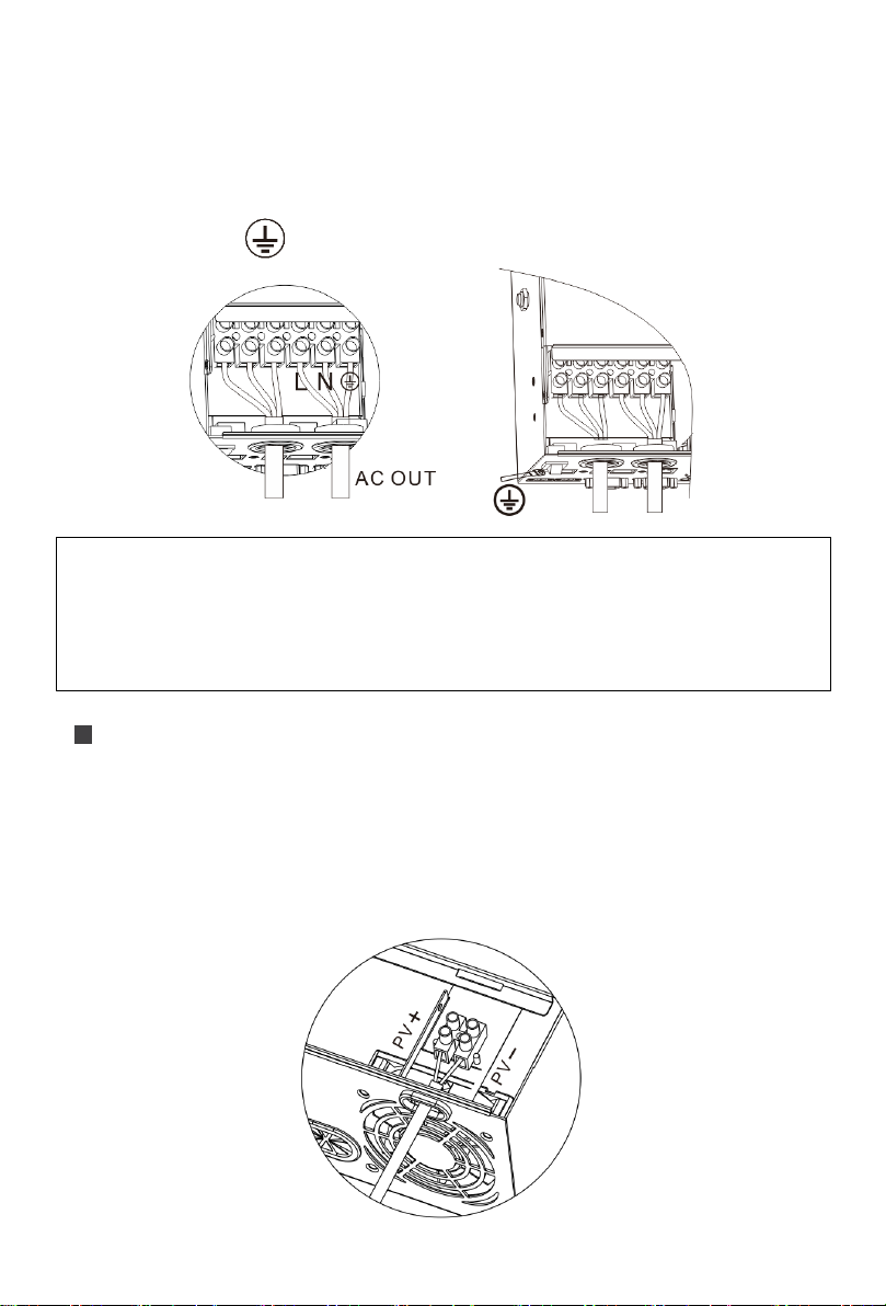
AC Input/Output Wiring
1. Before AC input/output wiring, disconnect the external breaker at first and then confirm whether
the cable used is thick enough. Please refer to section “Wiring Specification and Breaker type”;
2. Correctly connect AC input wire in accordance with cable sequence and terminal position shown
in the figure below. Please connect ground lead at first, and then live wire and mull wire;
: Ground L: Live N: Neutral
NOTICE
⚫Above wire diameter and breaker are only for reference. Please select appropriate wire
diameter and breaker based on practical condition.
14
3. Correctly connect AC output wire in accordance with cable sequence and terminal position
shown in the figure below. Please connect the ground wire at first, and then live wire and null
wire. The ground wire is connected to the ground screw hold through shaped terminal.
: Ground L: Live N: Neutral
PV Input Wiring
1. Before wiring, disconnect external breaker at first, and confirm whether the used cable is thick
enough. Please refer to section “Wiring Specification and Breaker Type”;
2. Correctly connect PV input wire in accordance with cable sequence and terminal position shown
in the figure below.
PV+: positive input pole PV-: negative input pole
NOTICE
⚫Use thick ground cable as far as possible (with cable section not less than 4mm²), place the
ground point to be close to the all-in-one inverter as far as possible and choose shorter
ground wire to the greatest extent.

15
Battery Wiring
1. Before wiring, disconnect external breaker at first, and then confirm whether the used cable is
thick enough. Please refer to section “Wiring Specification and Breaker Type”. BAT wire shall be
connected with the machine via O-shaped terminal. It is recommended to use the O-shaped
terminal with 6mm inside diameter. The O-shaped terminal must compress BAT wire firmly to
prevent excessive heating caused by great contact resistance;
2. Correctly connect BAT wire in accordance with cable sequence and terminal position shown in
the figure below.
BAT+: positive battery pole BAT-: negative battery pole
WARNING
⚫Input from mains supply, AC output and photovoltaic array may generate high voltage.
Before wiring, make sure to break the breaker or fuse;
⚫During wiring process, make sure to pay attention to the safety; during the wiring process,
please don’t close the breaker or fuse. At the same time, guarantee that “+” and “-” poles of
different parts are correctly connected with wires; a breaker must be installed at the battery
end and selected based on section “Wiring Specification and Breaker Type”. Before wiring,
make sure to break the breaker to prevent strong electric spark generated during wiring. At
the same time, avoid battery short circuit during the wiring process; if the all-in-one inverter is
in the area with frequent thunder, it is suggested to install an external arrester at PV input
terminal.
16
Final Assembly
1. After wiring, inspect whether the wires are correctly and firmly connected, especially whether the
positive and negative input poles of the battery are correct, whether the positive and negative
input poles of PV are correct, whether AC input is inaccurately connected to AC output terminal.
2. After ensuring that the wiring is reliable and the wire sequence is correct, install the terminal
protection cover in place.
Start up the inverter
1. At first close the breaker at the battery end, and then press the rocker switch at the lower left
side of the machine to “ON” state, “AC/INV” indicator light flashes, indicating normal operation of
inverter.
2. Afterwards, close breakers of photovoltaic array and mains supply.
3. In the end, after AC output is normal, turn on AC load one by one to avoid protection action
generated by great instant impact owing to simultaneous turn on the loads. The all-in-one
inverter operates normally in accordance with set mode.
NOTICE
⚫If power is supplied to different AC loads, it is suggested to turn on the loads with great
impact current, and then turn on the load with little impact current after the load operates
stably.
⚫In case of abnormal operation of all-in-one machine or abnormal display of LCD or indicator
light, refer to section “Troubleshooting”to handle the exceptions.
17
Operating Mode
Charge Mode
1. Photovoltaic priority: In photovoltaic priority charge mode, mains charge is started only when
photovoltaics is out of work. Make full use of solar energy for power generation in the daytime
and transfer to the mains supply for charge to maintain electric quantity of the battery. It is
suitable for areas with relatively stable power grid and relatively expensive electricity price.
2. Mains supply priority: Mains supply is to charge the battery preferentially and the photovoltaic
charge can be started only when the mains supply is valid.
3. Mixed charge: With mixed charge through photovoltaics and mains supply, photovoltaic MPPT
charge is used preferentially. In case of insufficient photovoltaic energy, the mains supply is
used for supplement. In case of sufficient photovoltaic energy, mains supply stops charge.
Electricity can be charged fastest with the way, which is suitable for the area with unstable
power grid, so as to supply sufficient backup power supply at any time.
4. Only solar: Only photovoltaic charge is used, no mains supply is started. This way can save the
energy at most. The electric energies of battery are all from solar energy. This way is suitable for
areas with good light condition.
Operation Mode

18
Output Mode
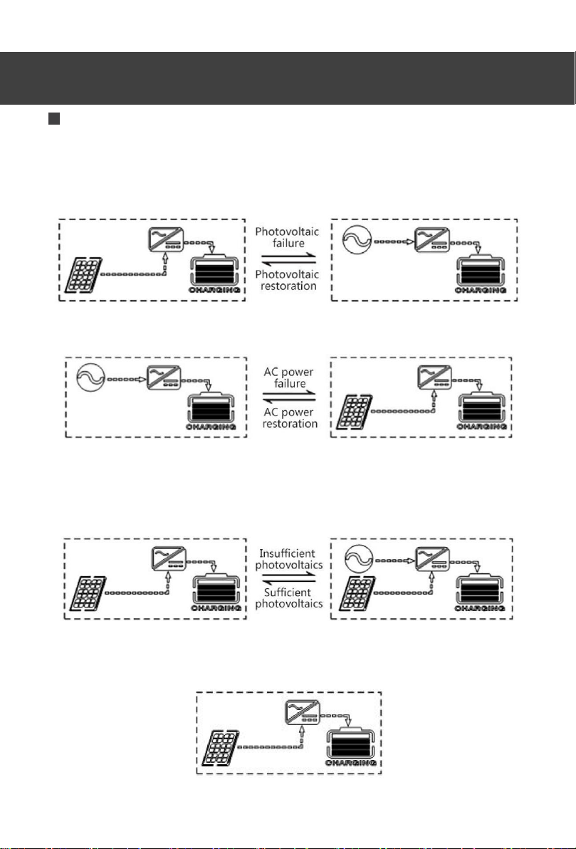
1. Photovoltaic priority mode: Photovoltaic and battery supply power to the load. With diversified
charge mode and optional output mode, when photovoltaic priority mode is selected, the green
solar energy can be used as far as possible so as to achieve energy conservation and emission
reduction.
It switches to mains supply when the photovoltaics is invalid. With the mode, solar energy can
be used maximally and electric quantity can be maintained at the same time. Therefore, the
mode is suitable for areas with stable power grid.
2. Mains supply priority mode: It only switches to inverter for power supply when mains supply is
invalid, equivalent toa backup UPS. Therefore, the modeis applicable to area with unstable power
grid.
3. Inverter priority mode: It only switches to mains supply in case of undervoltage of battery. With
the mode, DC electric energy is used maximally. Therefore, it is applied to the area with stable
power grid.
4. Mixed functions mode: When the battery is not available or the battery is fully charged, the
load is provided by PV and commercial power, PV maximum output power output.

19
Operation Instruction
Operation and Display Panel
⚫Touchable Keys
Function Key
Description
SET
Enter/exit setting menu
UP
Last option
DOWN
Next option
ENT
Confirm/enter option under setting menu
⚫LED Indicators
Indicator light
Color
Description
AC/INV
Yellow
Constant on: mains supply output
Flashing: inverter output
CHARGE
Green
Flashing: battery in charge
Constant on: charge completed
FAULT
Red
Constant on: fault state
Operation Instruction
Table of contents
Other PowMr Inverter manuals

PowMr
PowMr SOLXPOW X4 Series User manual

PowMr
PowMr POW-HVM5.5M User manual

PowMr
PowMr POW-HPM Series User manual

PowMr
PowMr POW-SunSmart 8KL3 User manual

PowMr
PowMr SOLXPOW X1 Series User manual

PowMr
PowMr POW-SunSmart 8KE User manual

PowMr
PowMr POW-LVM3K-24V-H User manual

PowMr
PowMr SOLXPOW X2 Series User manual
Popular Inverter manuals by other brands


Good Will Instrument
Good Will Instrument GFG-3015 Operation manual

TP-Solar
TP-Solar 30W solar Charger instruction manual

GÜDE
GÜDE GSE 2701 instructions

Fuji Electric Europe
Fuji Electric Europe FRENIC-Multi user manual

Green Cell
Green Cell 5902719422201 user guide

Dometic
Dometic MSI924M Installation and operating manual