PowMr POW-SunSmart 8KE User manual

1
Important Safety Instructions
Please save these instructions for future use!
Read all of the instructions and cautions in the manual before beginning the installation !
⚫Installation and wiring must comply with the Local and National Electric Codes (NEC).
⚫The controller must not be installed or operated by any of the following persons, unless they are
under strict instruction and supervision:
a. Anyone who lacks the appropriate knowledge, experience or competence, required for safe
installation and/or usage.
b. Anyone with compromised/reduced physical, sensory or mental capabilities, which may effect
safe installation and/or usage (including children).
⚫Do NOT disassemble or attempt to repair the inverter. There are no serviceable parts for this
inverter.
⚫DO NOT parallel this device with other AC input sources to avoid damage.
⚫Beware of high voltage. Please turn off the switch of each power sources before and during the
installation and connection to avoid electric shock.
⚫DO NOT attempt to touch the unit while it is operating as temperatures will be very hot. In
addition, do not open the terminal cover while the unit is in operation.
⚫Make sure all connections going into and from the inverter are tight. There may be sparks when
making connections, therefore, make sure there are not flammable materials or gases near
installation.
⚫Installing breakers or fuses outside of the unit is recommended.
⚫After installation, check that all line connections are tight and secured.
⚫Do NOT let the positive (+) and negative (-) terminals of the battery touch each other. Use
Lithium batteries or deep cycle Sealed Lead Acid, Flooded, Gel, AGM batteries.
⚫Explosive battery gases may be present while charging. Be certain there is enough ventilation to
release the gases.
⚫Be careful when working with large lead acid batteries. Wear eye protection and have fresh water
available in case there is contact with the battery acid.
⚫GROUNDING INSTRUCTIONS -This inverter/charger should be connected to a permanent
grounded wiring system. Be sure to comply with local requirements and regulation to install this
inverter.

2
⚫Over-charging and excessive gas precipitation may damage the battery plates and activate
material shedding on them. Too high of an equalizing charge or too long of one may cause
damage. Please carefully review the specific requirements of the battery used in the system.
⚫For optimum operation of this inverter, please follow required specification to select appropriate
cable size and necessary protective device.
⚫Never charge a frozen battery.
⚫Never cause AC output and DC input short circuited.
⚫Please keep children away from touching or mishandling the inverter.
⚫Please make sure that this inverter is the only input power source for the load, do not use it in
parallel with other input AC power sources to avoid damage.

3
Table of Contents
Important Safety Instructions....................................................................................................... 1
1 Safety.......................................................................................................................................... 5
1.1 How to Use This Manual .................................................................................................. 5
1.2 Symbols in This Manual .................................................................................................... 5
2 Production Instructions............................................................................................................. 5
2.1 Instructions ...................................................................................................................... 5
2.2 Features .......................................................................................................................... 6
2.3
System Connection Diagram
.......................................................................................... 7
2.4 Production Overview........................................................................................................ 8
3 Installation.................................................................................................................................. 9
3.1 Select the Mount Location................................................................................................ 9
3.2 Mount the Inverter.......................................................................................................... 10
3.3 Remove the Terminal Cover & Anti Insect Net................................................................ 10
4 Connection ................................................................................................................................11
4.1 Single-phase Output.......................................................................................................11
4.2 Cable & Circuit Breaker Requirement............................................................................. 13
4.3 AC Input & Output Connection ....................................................................................... 14
4.4 Battery Connection ........................................................................................................ 14
4.5 PV Connection............................................................................................................... 15
4.6 Dry Contact Connection................................................................................................. 16
4.7 Grounding Connection ................................................................................................... 16
4.8 Final Assembly............................................................................................................... 16
4.9 Start-up the Inverter ....................................................................................................... 16
5 Operation.................................................................................................................................. 17
5.1 Operation and Display Panel.......................................................................................... 17
5.2 Setting ........................................................................................................................... 21
5.3 AC Output Mode ............................................................................................................ 30
5.4 Battery Charging Mode .................................................................................................. 32
5.5 Time-slot Charging/Discharging Function....................................................................... 34
5.6 Battery Parameter.......................................................................................................... 35
Table of Contents

4
6 Communication........................................................................................................................ 37
6.1 Overview........................................................................................................................ 37
6.2 USB-B Port .................................................................................................................... 37
6.3 RS485-1 Port ................................................................................................................. 38
6.4 CAN/RS485-2 Port......................................................................................................... 38
6.5 Dry Contact.................................................................................................................... 39
7 Fault and Remedy .................................................................................................................... 40
7.1 Fault Code ..................................................................................................................... 40
7.2 Troubleshooting ............................................................................................................. 42
8 Protection and Maintenance.................................................................................................... 44
8.1 Protection Features........................................................................................................ 44
8.2
Maintenance
................................................................................................................ 46
9 Datasheet.................................................................................................................................. 47

5
1 Safety
1.1 How to Use This Manual
This manual contains important information
,
guidelines
,
operation and maintenance for the following
products: POW-SunSmart 8KE, POW-SunSmart 10KE.
The manual must be followed during installation and maintenance.
1.2 Symbols inThis Manual
Symbol
Description
DANGER
DANGER indicates a hazardous situations which if not avoided will result
in death or serious injury.
WARNING
WARING indicates a hazardous situations which if not avoided could
result in death or serious injury.
CAUTION
CAUTION indicates a hazardous situations which if not avoided could
result in minor or moderate injury.
NOTICE
NOTICE provide some tips on operation of products.
2 Production Instructions
2.1 Instructions
POW-SunSmart series is a new type of solar energy storage inverter control inverter integrating
solar energy storage & utility charging and energy storage, AC sine wave output. It adopts DSP
control and features high response speed, reliability, and industrial standard through an advanced
control algorithm.

6
2.2 Features
⚫Supports lead acid battery and li-ion battery connections.
⚫With a dual activation function when the li-ion battery is dormant; either mains/photovoltaic
power supply access can trigger the activation of the li-ion battery.
⚫Support split-phase and single-phase pure sine wave output.
⚫Supports four different voltage levels of 200\208\220\230\240Vac per phase.
⚫Supports two solar inputs and simultaneous tracking of two solar maximum power
charging/carrying capacity functions.
⚫Dual MPPT with 99.9% efficiency and maximum 22A current in a single circuit, perfectly adapted
to high power modules.
⚫charging modes are available: solar only, mains priority, solar priority, and mixed mains/PV
charging.
⚫With the time-slot charging and discharging setting function, you can set the time period for
cutting in/out of mains charging and switch the time period between battery discharging and
mains bypass power supply mode.
⚫Energy saving mode function to reduce no-load energy losses.
⚫With two output modes of utility bypass and inverter output, with uninterrupted power supply
function.
⚫LCD large screen dynamic flow diagram design, easy to understand the system data and
operation status.
⚫360°protection with complete short circuit protection, over current protection, over under voltage
protection, overload protection, backfill protection, etc.
⚫Support CAN, USB, and RS485 communication.

7
2.3
System Connection Diagram
The diagram below shows the system application scenario of this product. A complete system
consists of the following components:
1. PV modules: converts light energy into DC energy, which can be used to charge the battery via
an inverter or directly inverted into AC power to supply the load.
2. Utility grid or generator: connected to the AC input, it can supply the load and charge the
battery at the same time. The system can also operate generally without the mains or generator
when the battery and the PV module power the load.
3. Battery: The role of the battery is to ensure the regular power supply of the system load when
the solar energy is insufficient and there is no mains power.
4. Home load: Various household and office loads can be connected, including refrigerators,
lamps, televisions, fans, air conditioners, and other AC loads.
5. Inverter: The energy conversion device of the whole system.
The actual application scenario determines the specific system wiring method.
8
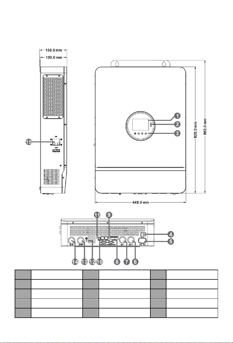
2.4 Production Overview
1
LCD screen
2
Touchable key
3
LED Indicators
4
ON/OFF Rocker Switch
5
PV INPUT (1/1)
6
BAT INPUT (+)
7
BAT INPUT (-)
8
Dry contact
9
CAN/RS485-2 port
10
RS485-1 port
11
USB-B port
12
Grounding Screw
13
AC OUT (L+N)
14
AC IN (L+N)
15
AC INPUT breaker

9
3 Installation
3.1 Select the Mount Location
POW-SunSmart series are designed for INDOOR USE ONLY (IP20). Please consider the
followings before selecting the location.
⚫Choose the solid wall to install the inverter.
⚫Mount the inverter at eye level.
⚫Adequate heat dissipation space must be provided for the inverter.
⚫The ambient temperature should be between -10~55℃(-14~131℉) to ensure optimal
operation.
DANGER
⚫Do not install the inverter where highly flammable materials are near by.
⚫Do not install the inverter in potential explosive areas.
⚫Do not install the inverter with lead-acid batteries in a confined space.
CAUTION
⚫Do not install the inverter in direct sunlight.
⚫Do not install or use the inverter in a humid environment.
10
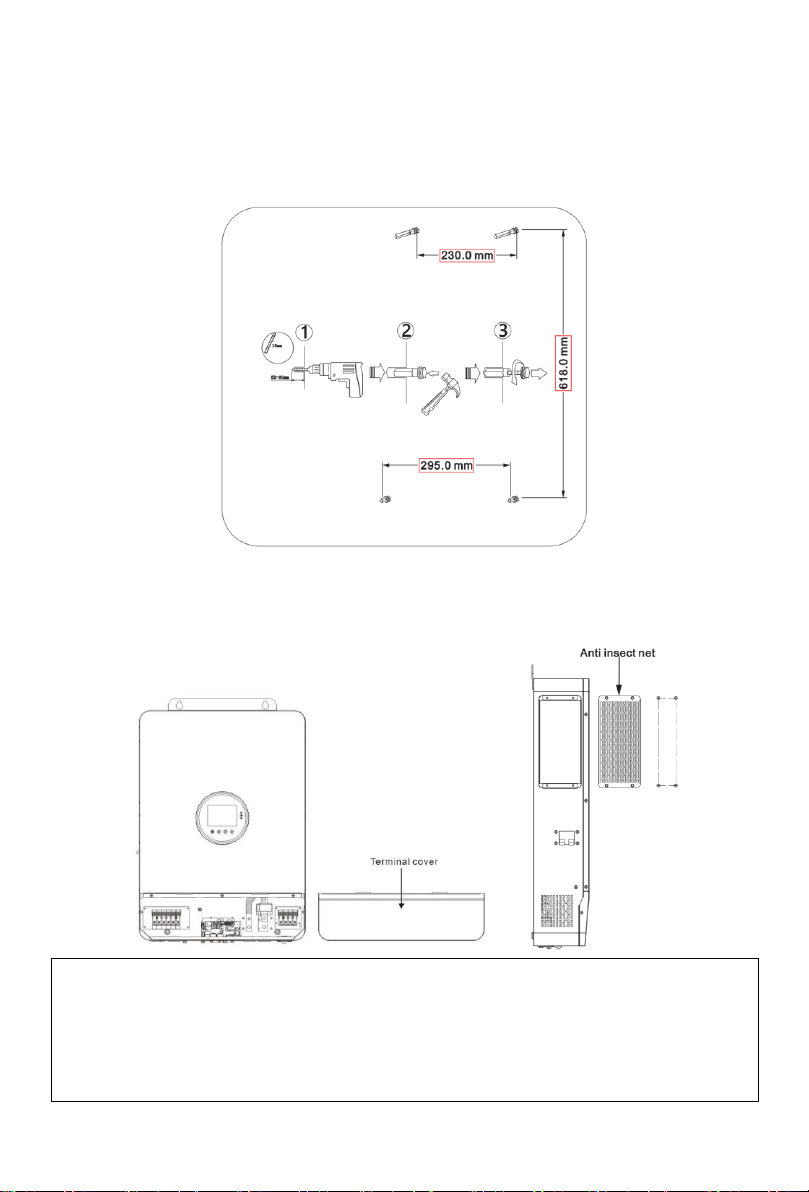
3.2 Mount the Inverter
Make 4 mounting holes in the wall with a drill according to the specified dimensions, insert two
expansion screws above and two M5 size screws below for fixing the inverter.
3.3 Remove the Terminal Cover & Anti Insect Net
Using a screwdriver, remove the terminal protection cover and anti-insect net.
NOTICE
⚫When using the device in areas with poor air quality, the dust screen is easily blocked by
airborne particles. Please dismantle and clean the dust screen regularly to avoid affecting the
internal air flow rate of the inverter, which may trigger an over-temperature protection fault
(19/20 fault) affecting the use of the power supply and the service life of the inverter.

11
4 Connection
4.1 Single-phase Output
Items
Description
Applicable Model
POW-SunSmart series S model
Output Voltage Range (L-N)
200~240Vac, 230Vac default
NOTICE
⚫Users can change the output voltage by setup menu. Please read the chapter 5.2 Setting.
⚫Output voltage corresponds parameter 38, the output voltage can be set from 200V to 240V.

12

13
4.2 Cable & Circuit Breaker Requirement
⚫PV INPUT
Model
Cable Diameter
Max.PV Input Current
Circuit Breaker Spec
POW-SunSmart 8KE
5mm²/ 10AWG
22A
2P-25A
POW-SunSmart 10KE
5mm²/ 10AWG
22A
2P-25A
⚫AC INPUT
Model
Output Mode
Max.Input Current
Cable diameter
Circuit Breaker
Spec
POW-SunSmart 8KE
Single-phase
63A (L/N)
13mm²/ 6AWG
2P-63A
POW-SunSmart 10KE
Single-phase
63A (L/N)
13mm²/ 6AWG
2P-63A
⚫BATTERY
Model
Cable Diameter
Max.Battery Current
Circuit Breaker Spec
POW-SunSmart 8KE
34mm²/ 2AWG
180A
2P-200A
POW-SunSmart 10KE
42mm²/ 1AWG
220A
2P-250A
⚫AC OUTPUT
Model
Output Mode
Max. Output
Current
Cable diameter
Circuit Breaker
Spec
POW-SunSmart 8KE
Single-phase
63A (L/N)
13mm²/ 6AWG
2P-63A
POW-SunSmart 10KE
Single-phase
63A (L/N)
13mm²/ 6AWG
2P-63A
NOTICE
⚫PV INPUT、AC INPUT、AC OUTPUT
1. Use a stripper to remove the 6~8mm insulation
of the cable.
2. Fixing a ferrule at the end of the cable. (ferrule
needs to be prepared by the user)
⚫BATTERY
1. Use a stripper to remove the 6~8mm insulation
of the cable
2. Fixing cable lugs that supply with the box at the
end of the cable.
The wire diameter is for reference only. If the distance between the PV array and the inverter or
between the inverter and the battery is long, using a thicker wire will reduce the voltage drop
and improve the performance of the system.
14
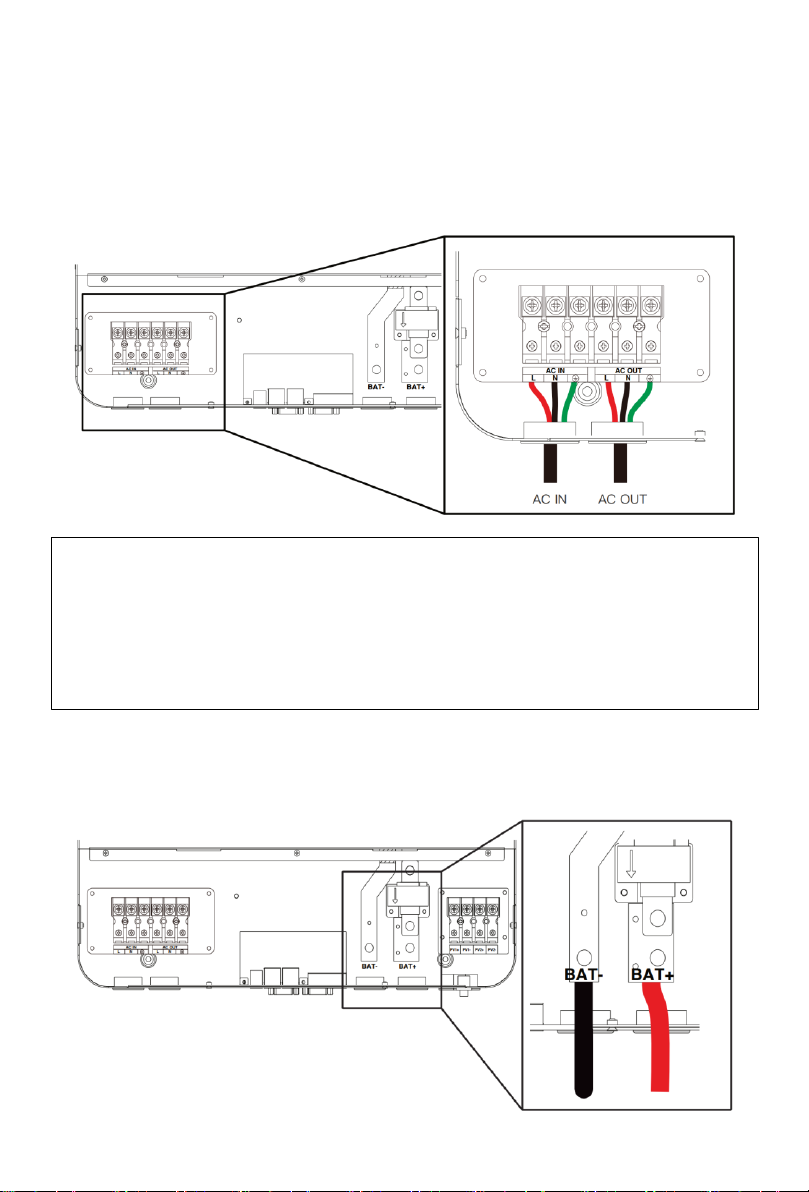
4.3 AC Input & Output Connection
Connect the live, neutral and ground wires according to the cables’ position and order shown in the
diagram below.
4.4 Battery Connection
Connect the positive and negative cable of the battery according to the diagram below.
DANGER
⚫Before connecting AC inputs and outputs, the circuit breaker must be opened to avoid the
risk of electric shock and must not be operated with electricity.
⚫Please check that the cable used is sufficient for the requirements, too thin, poor quality
cables are a serious safety hazard.
15
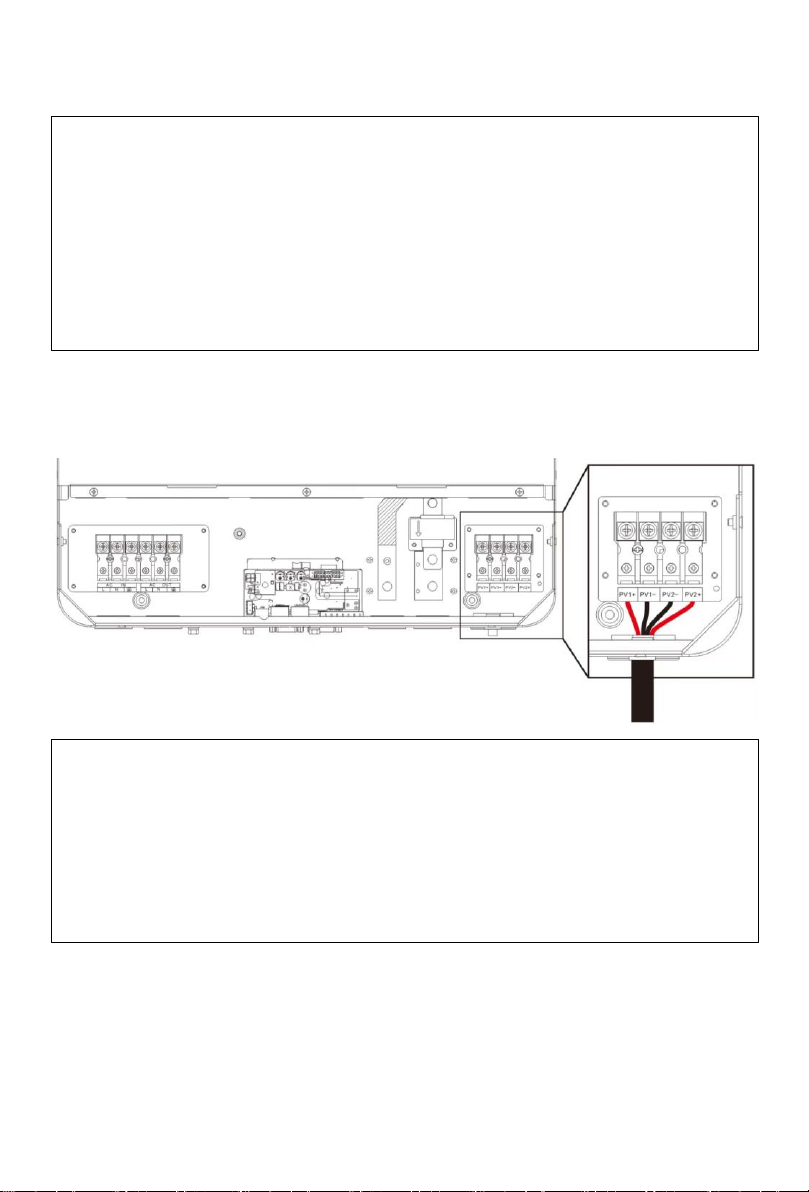
4.5 PV Connection
Connect the positive and negative wires of the two strings of PV according to the diagram below.
DANGER
⚫Before connecting battery, the circuit breaker must be opened to avoid the risk of electric
shock and must not be operated with electricity.
⚫Make sure that the positive and negative terminals of the battery are connected correctly and
not reversed, otherwise the inverter may be damaged.
⚫Please check that the cable used is sufficient for the requirements, too thin, poor quality
cables are a serious safety hazard.
DANGER
⚫Before connecting PV, the circuit breaker must be opened to avoid the risk of electric shock
and must not be operated with electricity.
⚫Please make sure that the open circuit voltage of the PV modules in series does not exceed
the Max. Open Circuit Voltage of the inverter (In the POW-SunSmart series, this value is
500V), otherwise the inverter may be damaged.
16
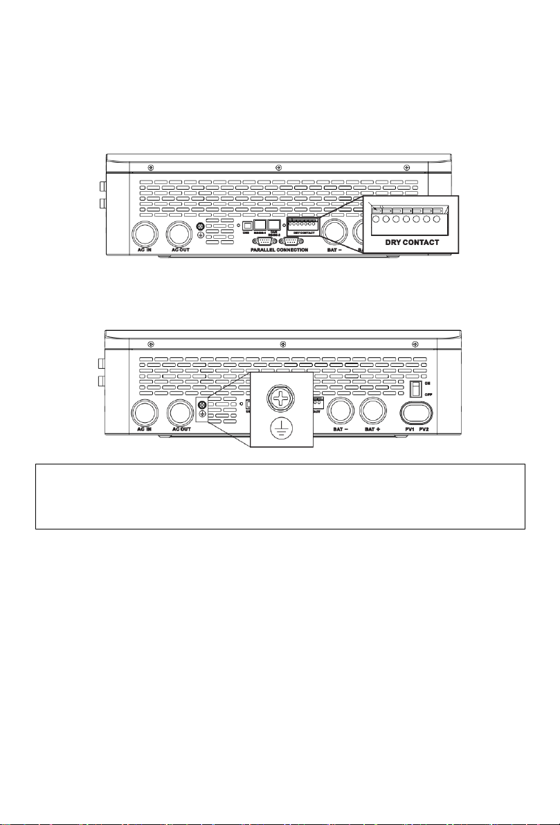
4.6 Dry Contact Connection
Use a small screwdriver to push back the direction indicated by the arrow, then insert the
communication cable into the dry junction port. (Communication cable diameter 0.2~1.5mm²)
4.7 Grounding Connection
Please make sure the grounding terminal connect to the Grounding Bar.
4.8 Final Assembly
After ensuring that the wiring is reliable and the wire sequence is correct, install the terminal
protection cover in place.
4.9 Start-up the Inverter
Step 1. Close the circuit breaker of the battery.
Step 2. Press the rocker switch on the bottom of inverter, the screen and indicators light up to
indicate that the inverter has been activated.
Step 3. Sequential close of the circuit breakers for PV, AC input and AC output.
Step 4. Start the loads one by one in order of power from small to large.
NOTICE
⚫The grounding cable should have a diameter of not less than 4 mm² and be as close as
possible to the grounding point.

17
5 Operation
5.1 Operation and Display Panel
The operation and display panel below includes 1 LCD screen, 3 indicators, 4 touchable keys.
⚫Touchable Keys
Touchable Keys
Description
To enter/exit the setting menu
To next selection
To last selection
To confirm/enter the selection in setting menu
⚫LED Indicators
Indicators
Color
Description
AC/INV
Green
Continued: utility grid by-pass output
Flash: inverter output
CHARGE
Yellow
Continued: charging complete
Flash: charging
FAULT
Red
Flash: error occur
18
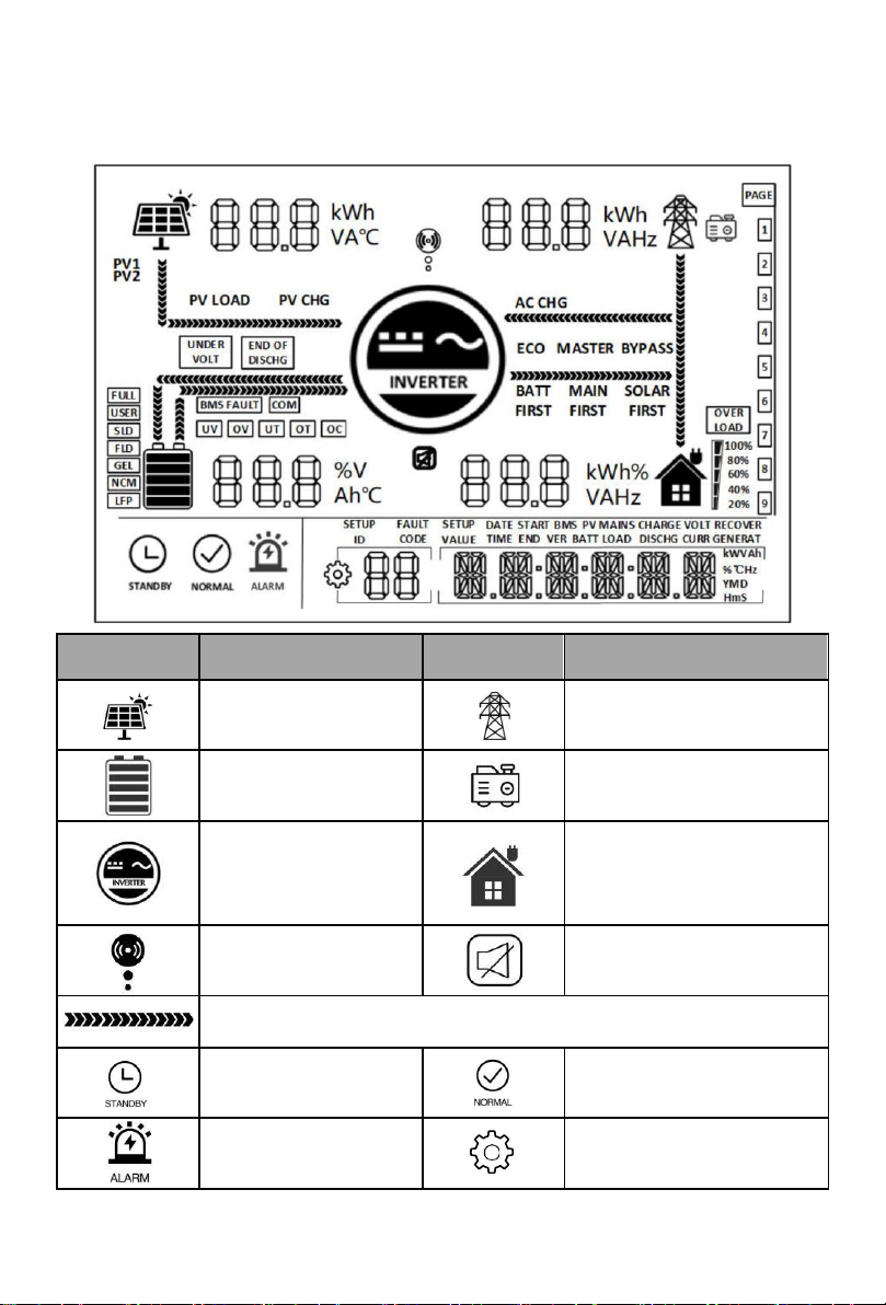
⚫Display panel
Icon
Description
Icon
Description
Indicates the PV panel
Indicates the utility grid
Indicates the battery
Indicates the generator
Indicates the inverter is
working
Indicates the home load
Indicates the inverter is
communicating with data
collector
Indicates the buzzer muted
Indicates the direction of energy flow
Indicates the inverter is
standby
Indicates the inverter is working
normally
Indicates error occur
Indicates setting
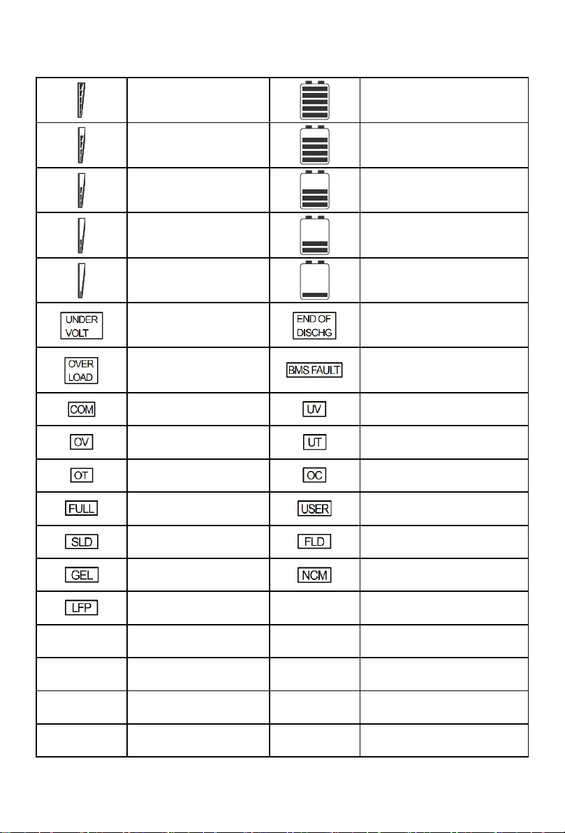
19
Indicates load power
80%~100%
Indicates battery SOC
80%~100%
Indicates load power
60%~79%
Indicates battery SOC 60%~79%
Indicates load power
40%~59%
Indicates battery SOC 40%~59%
Indicates load power
20%~39%
Indicates battery SOC 20%~39%
Indicates load power
5%~19%
Indicates battery SOC 5%~19%
Indicates battery under-
voltage
Indicates battery discharge
Indicates over-load
Indicates BMS fault
Indicates system
communication error
Indicates system under-voltage
Indicates system over-
voltage
Indicates system under-
temperature
Indicates system over-
temperature
Indicates system over-current
Indicates battery is full
Indicates user defined battery
Indicates sealed lead-acid
battery
Indicates flooded lead-acid
battery
Indicates gel lead-acid
battery
Indicates ternary li-ion battery
Indicates LFP li-ion battery
ECO
Indicates energy-saving mode
PV LOAD
Indicates PV energy is
carrying the load
PV CHG
Indicates PV energy is charging
the battery
AC CHG
Indicates AC IN energy is
charging the battery
MAIN
FIRST
Indicates the inverter output
mode is mains power first
BYPASS
Indicates the inverter output
mode is bypass
SOLAR
FIRST
Indicates the inverter output
mode is solar first
BATT
FIRST
Indicates the inverter output
mode is battery first
This manual suits for next models
1
Table of contents
Other PowMr Inverter manuals

PowMr
PowMr SOLXPOW X1 Series User manual

PowMr
PowMr POW-LVM3K-24V-H User manual

PowMr
PowMr SOLXPOW X4 Series User manual

PowMr
PowMr POW-LVM5K-48V-N User manual

PowMr
PowMr SOLXPOW X2 Series User manual

PowMr
PowMr POW-HPM Series User manual

PowMr
PowMr POW-HVM5.5M User manual

PowMr
PowMr POW-SunSmart 8KL3 User manual
Popular Inverter manuals by other brands


EMS
EMS Piezon P18 installation instructions

Jntech
Jntech JNP550L-V5 Quick installation

Champion Global Power Equipment
Champion Global Power Equipment 500740-WL-EU Operator's manual

Delixi Drives
Delixi Drives WS-160MX manual

SMA
SMA NR-STP-DC-EMV Replacement manual

CHNT Power
CHNT Power CPS SCA-T Series Installation and operation manual