PowMr POW-LVM3K-24V-H User manual


1
Important Safety Instructions
Please save these instructions for future use!
This manual contains all safety, installation and operating instructions for the POW-LVM3K Series
all-in-one solar charge inverter.
Please read all instructions and precautions in the manual carefully before installation and
use.
⚫Non-safety voltage exists inside the all-in-one solar charge inverter. To avoid personal injury,
users shall not disassemble the all-in-one solar charge inverter themselves. Contact our
professional maintenance personnel if there is a need for repair.
⚫Do not place the all-in-one solar charge inverter within the reach of children.
⚫Do not install the all-in-one solar charge inverter in harsh environments such as moist, oily,
flammable or explosive, or heavily dusty areas.
⚫The mains input and AC output are high voltage, so please do not touch the wiring terminals.
⚫The housing of the all-in-one solar charge inverter is hot when it is working. Do not touch it.
⚫Do not open the terminal protective cover when the all-in-one solar charge inverter is working.
⚫It is recommended to attach proper fuse or circuit breaker to the outside of the all-in-one solar
charge inverter.
⚫Always disconnect the fuse or circuit breaker near the terminals of PV array, mains and battery
before installing and adjusting the wiring of the all-in-one solar charge inverter.
⚫After installation, check that all wire connections are tight to avoid heat accumulation due to poor
connection, which is dangerous.
⚫The all-in-one solar charge inverter is off-grid. It is necessary to confirm that it is the only input
device for load, and it is forbidden to use it in parallel with other input AC power to avoid
damage.

2
Important Safety Instructions....................................................................................................... 1
Production Instructions................................................................................................................ 4
Features ................................................................................................................................. 5
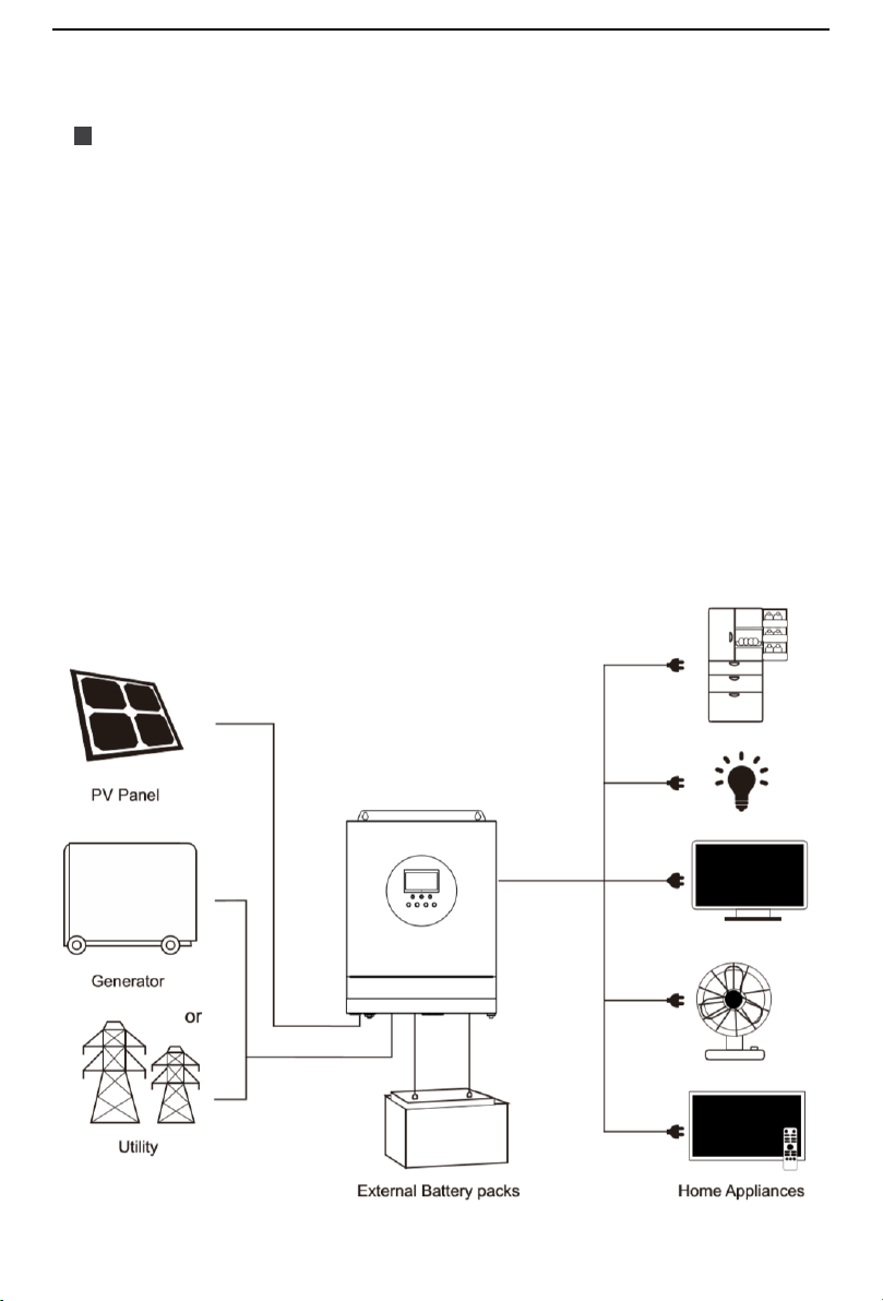
Basic System Introduction....................................................................................................... 6
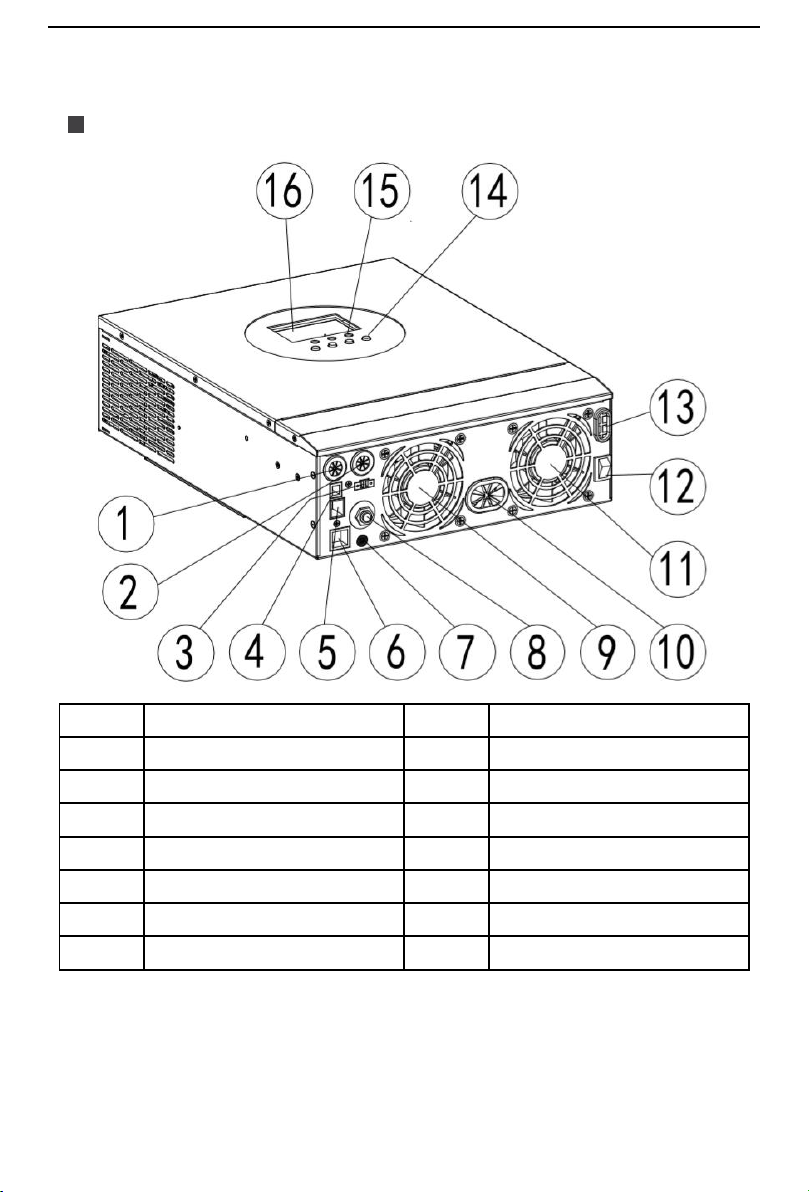
Production Overview............................................................................................................... 7
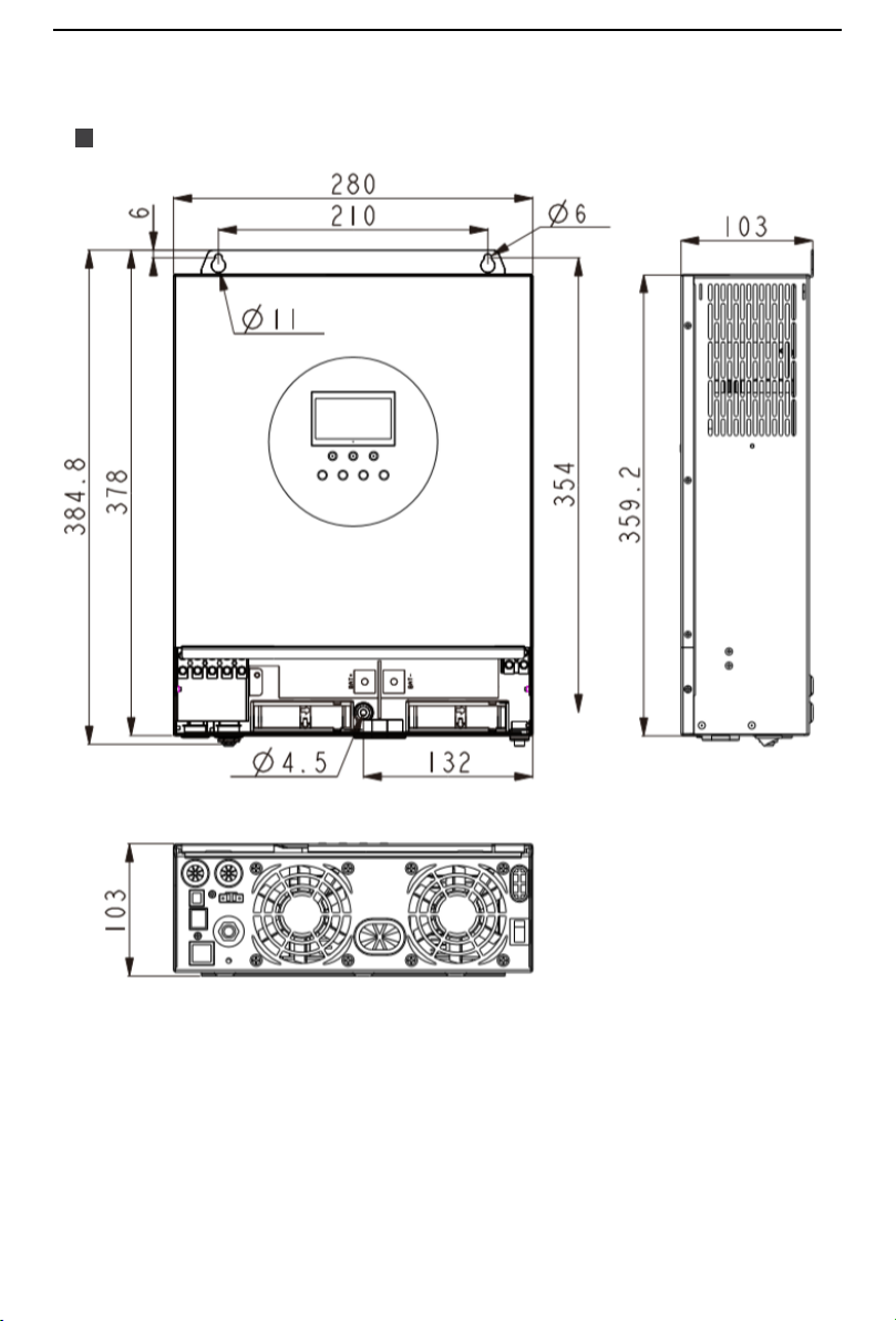
Dimension Drawing................................................................................................................. 8
Installation..................................................................................................................................... 9
Installation Notice ................................................................................................................... 9
Select the Mount Location..................................................................................................... 10
Mount the Inverter................................................................................................................. 10
Preparation............................................................................................................................11
Connection .................................................................................................................................. 12
Wiring Specification and Breaker Type.................................................................................. 12
AC Input/Output Wiring ......................................................................................................... 13
PV Input Wiring..................................................................................................................... 14
Battery Wiring....................................................................................................................... 15
Final Assembly..................................................................................................................... 16
Start Up the Inverter ............................................................................................................ 16
Operation Mode........................................................................................................................... 17
Charging Mode ..................................................................................................................... 17
Output Mode......................................................................................................................... 18
Operation Instruction.................................................................................................................. 19
Operation and Display Panel ................................................................................................ 19
Introduction to LCD Screen................................................................................................... 20
Real-time Data Viewing Method............................................................................................ 22
Setting Parameter................................................................................................................. 23
Battery Type Parameters ...................................................................................................... 32
Other Functions .......................................................................................................................... 34
Dry Node .............................................................................................................................. 34
RS485 Communication Port.................................................................................................. 34
Table of Contents

3
CAN Communication Function.............................................................................................. 34
USB communication port ...................................................................................................... 34
Protection.................................................................................................................................... 35
Protections Provided............................................................................................................. 35
Fault Code Meaning ............................................................................................................. 37
Troubleshooting .................................................................................................................... 39
System maintenance .................................................................................................................. 40
Technical parameters ................................................................................................................. 41

4
Production Instructions
POW-LVM3K series is a new all-in-one hybrid solar charge inverter, which integrates solar energy
storage & means charging energy storage and AC sine wave output. Thanks to DSP control and
advanced control algorithm, it has high response speed, high reliability and high industrial standard.
Four charging modes are optional, i.e. Only Solar, Mains Priority, Solar Priority and Mains & Solar
hybrid charging; and two output modes are available, i.e. Inverter and Mains, to meet different
application requirements.
The solar charging module applies the latest optimized MPPT technology to quickly track the
maximum power point of the PV array in any environment and obtain the maximum energy of the
solar panel in real time.
Through a state of the art control algorithm, the AC-DC charging module realizes fully digital
voltage and current double closed loop control, with high control precision in a small volume. Wide
AC voltage input range and complete input/output protections are designed for stable and reliable
battery charging and protection.
Based on full-digital intelligent design, the DC-AC inverter module employs advanced SPWM
technology and outputs pure sine wave to convert DC into AC. It is ideal for AC loads such as
household appliances, power tools, industrial equipment, and electronic audio and video
equipment. The product comes with a segment LCD display design which allows real-time display
of the operating data and status of the system. Comprehensive electronic protections keep the
entire system safer and more stable.
Production Instructions

5
Features
⚫Full digital voltage and current double closed loop control, advanced SPWM technology, output
of pure sine wave.
⚫Two output modes: Mains bypass and inverter output; Uninterrupted power supply.
⚫Available in 4 charging modes: Only Solar, Mains Priority, Solar Priority and Mains and Solar
hybrid charging.
⚫Advanced MPPT technology with an efficiency of 99.9%.
⚫Designed with a LCD screen and 3 LED indicators for dynamic display of system data and
operating status.
⚫ON/OFF rocker switch for AC output control.
⚫Power saving mode available to reduce no-load loss.
⚫Intelligent variable speed fan to efficiently dissipate heat and extend system life.
⚫Lithium battery activation by PV solar or mains, allowing access of lead-acid battery and lithium
battery.
⚫360 °all-round protection with a number of protection functions.
⚫Complete protections, including short circuit protection, over voltage and under voltage
protection, overload protection, reverse protection, etc.

6
Basic System Introduction
The figure below shows the system application scenario of this product. A complete system
consists of the following parts:
1. PV module: Convert light energy into DC power, and charge the battery through the all-in-one
solar charge inverter, or directly invert into AC power to drive the load.
2. Mains or generator: Connected at the AC input, to power the load while charging the battery. If
the mains or generator is not connected, the system can also operate normally, and the load is
powered by the battery and PV module.
3. Battery: Provided to ensure normal power supply to the system loads when solar energy is
insufficient and the Mains is not connected.
4. Household load: Allow connection of various household and office loads, including
refrigerators, lamps, TVs, fans and air conditioners.
5. All-in-one solar charge inverter: The energy conversion unit of the whole system.
Specific system wiring method depends on the actual application scenario.

7
Production Overview
①
AC input port
⑨
Cooling fan
②
AC output port
⑩
Battery port
③
CAN communication port
⑪
Cooling fan
④
USB communication port
⑫
ON/OFF rocker switch
⑤
RS485 communication port
⑬
PV port
⑥
Dry contact port
⑭
Touch the key lightly
⑦
Grounding screw hole
⑮
LED Indicator
⑧
Overload protector
⑯
LCD screen

8
Dimension Drawing

9
Installation
Installation Notice
Please read this manual carefully prior to installation to familiarize yourself with the installation
steps.
⚫Be very careful when installing the battery. Wear safety goggles when installing a lead-acid
liquid battery. Once coming into contact with the battery acid, rinse with clean water timely.
⚫Do not place metal objects near the battery to prevent short-circuit of the battery.
⚫Acid gas may be generated when the battery is charged. So, please ensure good ventilation.
⚫When installing the cabinet, be sure to leave enough space around the all-in-one solar charge
inverter for heat dissipation. Do not install the all-in-one solar charge inverter and lead-acid
battery in the same cabinet to avoid corrosion by acid gas generated during battery operation.
⚫Only the battery that meets the requirements of the all-in-one unit can be charged.
⚫Poorly connected connections and corroded wires may cause great heat which will melt the wire
insulation, burn the surrounding materials, and even cause fires. So, make sure the connectors
have been tightened, and the wires are secured with ties to avoid looseness of connections
caused by shaking of wires during mobile application.
⚫The system connection wires are selected according to a current density of not more than 5
A/mm².
⚫Avoid direct sunlight and rainwater infiltration for outdoor installation.
⚫Even after the power is turned off, there is still high voltage inside the unit. Do not open or touch
the internal components, and avoid related operations until the capacitor completely discharges.
⚫Do not install the all-in-one solar charge inverter in harsh environments such as moist, oily,
flammable or explosive, or heavily dusty areas.
⚫Polarity at the battery input end of this product shall not be reversed, otherwise it may damage
the device or cause unpredictable danger.
⚫The mains input and AC output are high voltage, so please do not touch the wiring terminals.
⚫When the fan is working, do not touch it to prevent injury.
⚫Load equipment input power needs to confirm that this all-in-one solar charge inverter is the only
input device, and it is forbidden to use in parallel with other input AC power to avoid damage. It
is necessary to confirm that the solar charge inverter is the only input device for load equipment,
and it is forbidden to use it in parallel with other input AC power to avoid damage.
Installation

10
Select the Mount Location
Determine the installation position and the space for heat dissipation.
⚫Determine the installation position of the all-in-one solar charge inverter, such as wall surface;
⚫When installing the all-in-one solar charge inverter, ensure that there is enough air flowing
through the heat sink, and space of at least 200m to the left and right air outlets of the inverter
shall be left to ensure natural convection heat dissipation. Refer to the installation diagram of the
whole machine as above.
Mount the Inverter
Install the unit by screwing two screws. It’s recommended to use M5 screws.
WARNING
⚫Danger of explosion! Never install the all-in-one solar charge inverter and lead-acid battery in
the same confined space! Also do not install in a confined place where battery gas may
collect.

11
Preparation
Before connecting all wirings, please take off bottom cover by removing two screws as shown
below.

12
Connection
Wiring Specification and Breaker Type
Wiring and installation must comply with national and local electrical codes.
Recommended PV array wiring specifications and circuit breaker selection: Since the output current
of the PV array is affected by the type, connection method and illumination angle of the PV module,
the minimum wire diameter of the PV array is calculated according to its short-circuit current; refer
to the short-circuit current value in the PV module specification (the short-circuit current is constant
when the PV modules are connected in series; the short-circuit current is the sum of the short-
circuit currents of all PV modules connected in parallel); the short-circuit current of the PV array
shall not exceed the maximum input current.
➢Please refer to the table below for PV input wire diameter and switch:
Model
Wire Diameter
Max. PV input current
Circuit breaker Spec
POW-LVM3K-24V-H
3.5mm²/12AWG
13A
2P—25A
Note: The voltage in series shall not exceed the maximum PV input open circuit voltage.
➢Please refer to the table below for recommended AC input wire diameter and switch:
Model
Wire Diameter
Max. bypass input
current
Circuit breaker Spec
POW-LVM3K-24V-H
6mm²/10AWG
40A
2P—40A
Note: There is already acorresponding breaker at input connection point of mains supply. Therefore,
it is not necessary to add one more.
➢Recommended input wire diameter and switch type for battery:
Model
Wire
Diameter
Rated Battery
Discharge Current
Max. Charge
Current
Circuit Breaker
Spec
POW-LVM3K-
24V-H
30mm²/2AWG
135A
80A
2P—160A
➢Recommended wire specification and breaker type for AC output:
Model
Wire diameter
Rated Inverter AC
Output current
Max. bypass
output current
Circuit Breaker
Spec
POW-LVM3K-
24V-H
6mm²/10AWG
27.5A
40A
2P—40A
Note: The wire diameter is only for reference. In case of long distance between photovoltaic array
and all-in-one inverter or between all-in-one inverter and battery, use thicker wire to reduce voltage
drop and improve system performance.
Connection

13
AC Input/Output Wiring
1. Prior to AC input/output wiring, disconnect the external circuit breaker and confirm that the wire
used is thick enough. Please refer to Section “Wiring Specification and Breaker Type”;
2. Properly connect the AC input wire according to the wire sequence and terminal position shown
in the figure below. Please connect the ground wire first, and then the live wire and the neutral
wire;
: Ground L: Live N: Neutral
NOTICE
⚫Above wire diameter and breaker are only for reference. Please select appropriate wire
diameter and breaker based on practical condition.

14
3. Properly connect the AC output wire according to the wire sequence and terminal position
shown in the figure below. Please connect the ground wire first, and then the live wire and the
neutral wire. The ground wire is connected to the grounding screw hole on the cabinet through
the O-type terminal.
:Ground L: Live N: Neutral
PV Input Wiring
1. Before wiring, disconnect external breaker at first, and confirm whether the used cable is thick
enough. Please refer to section “Wiring Specification and Breaker Type”;
2. Correctly connect PV input wire in accordance with cable sequence and terminal position shown
in the figure below.
PV+: positive input pole PV-: negative input pole
NOTICE
⚫The grounding wire shall be as thick as possible (cross-sectional area is not less than 4mm²).
The grounding point shall be as close as possible to the all-in-one solar charge inverter. The
shorter the grounding wire, the better.

15
Battery Wiring
1. Prior to wiring, disconnect the external circuit breaker and confirm that the wire used is thick
enough. Please refer to Section “Wiring Specification and Breaker Type”. The BAT wire needs to
be connected to the machine through the O-type terminal. The O-type terminal with an inner
diameter of 5 mm is recommended. The O-type terminal shall firmly press the BAT wire to
prevent excessive heat generation caused by excessive contact resistance;
2. Properly connect the BAT wire according to the wire sequence and terminal position shown in
the figure below.
BAT+: positive battery pole BAT-: negative battery pole
WARNING
⚫Mains input, AC output and PV array will generate high voltage. So, before wiring, be sure to
disconnect the circuit breaker or fuse;
⚫Be very careful during wiring; do not close the circuit breaker or fuse during wiring, and
ensure that the “+” and “-” pole leads of each component are connected properly; a circuit
breaker must be installed at the battery terminal. Refer to Section “Wiring Specification and
Breaker Type” to select a right circuit breaker. Before wiring, be sure to disconnect the circuit
breaker to prevent strong electric sparks and avoid battery short circuit; if the all-in-one solar
charge inverter is used in an area with frequent lightning, it is recommended to install an
external lightening arrester at the PV input terminal.

16
Final Assembly
1. After wiring, inspect whether the wires are correctly and firmly connected, especially whether the
positive and negative input poles of the battery are correct, whether the positive and negative
input poles of PV are correct, whether AC input is inaccurately connected to AC output terminal.
2. After ensuring that the wiring is reliable and the wire sequence is correct, install the terminal
protection cover in place.
Start Up the Inverter
1. At first close the breaker at the battery end, and then press the rocker switch
at the lower left side of the machine to “ON” state, “AC/INV” indicator light
flashes, indicating normal operation of inverter.
2. Afterwards, close breakers of photovoltaic array and mains supply.
3. In the end, after AC output is normal, turn on AC load one by one to avoid
protection action generated by great instant impact owing to simultaneous turn
on the loads. The inverter operates normally in accordance with set mode.
NOTICE
⚫If power is supplied to different AC loads, it is recommended to first turn on the load with a
large surge current. After the load is stable, turn on the load with a small surge current.
⚫If the all-in-one solar charge inverter does not work properly or the LCD or indicator is
abnormal, refer to section “Troubleshooting”to handle the exceptions.

17
Operation Mode
Charging Mode
1. PV priority: PV module will charge the battery preferentially, and the battery is charged by the
Mains only when the PV system fails. During the day, solar energy is fully used to charge, while
at night, it converts to the Mains. This can maintain battery level, and is ideal for areas where the
grid is relatively stable and electricity price is relatively high.
2. Mains priority: The Mains supply is preferentially used to charge the battery. Only when the
Mains fails, the PV charging can be activated.
3. Hybrid charging: PV and mains hybrid charging. PV MPPT charging is a priority, and when PV
energy is insufficient, the mains supply supplements. When the PV energy is sufficient again,
the mains stops charging. This is the fastest charging mode, suitable for the areas where power
grid is unstable, providing sufficient backup power supply at any time.
4. Only Solar (Only Solar): Only PV charging, without Mains charging. This is the most energy-
efficient way in which battery is charged only by solar panels, and is usually used in areas with
good lighting conditions.
Operation Mode

18
Output Mode
1. PV priority mode: Switch to mains supply when the PV charging fails. This mode maximizes
the use of solar energy while maintaining battery power, suitable for use in the areas with
relatively stable grid.
2. Mains priority mode: Switch to inverter only when the mains fails (when there was mains
power, switch to mains power for charging and power supply). Then, the unit is equivalent to a
backup UPS, suitable for areas with unstable grid. Switching does not affect PV charging.
3. Inverter priority mode: Switch to mains supply only when the battery discharge undervoltage is
lower than the set point (item 04). When the charging battery is higher than the set point of (05
setting item), switch to the battery discharge mode. This can cycle the battery charge and
discharge. This mode maximizes the use of DC power and is used in the area with stable grid.
Switching does not affect PV charging.
4. Mixed functions mode: When the battery is not available or the battery is fully charged, the
load is provided by PV and commercial power, PV maximum output power output.

19
Operation Instruction
Operation and Display Panel
The operation and display panel is as shown below, including 1 LCD screen, 3 indicators and 4
operation buttons.
⚫Touchable Keys
⚫LED Indicators
Function buttons
Description
SET
Enter/Exit Settings menu
UP
Previous choice
DOWN
Next choice
ENT
Confirm/Enter Options under the settings menu
Indicators
Colors
Description
AC/INV
Yellow
Steady on: Mains output
Flash: Inverter output
CHARGE
Green
Flash: Battery charging
Steady on: Charging completed
FAULT
Red
Flash: Fault state
Operation Instruction
Table of contents
Other PowMr Inverter manuals

PowMr
PowMr SOLXPOW X1 Series User manual

PowMr
PowMr SOLXPOW X2 Series User manual

PowMr
PowMr POW-HPM Series User manual

PowMr
PowMr POW-LVM5K-48V-N User manual

PowMr
PowMr POW-SunSmart 8KE User manual

PowMr
PowMr POW-HVM5.5M User manual

PowMr
PowMr SOLXPOW X4 Series User manual

PowMr
PowMr POW-SunSmart 8KL3 User manual