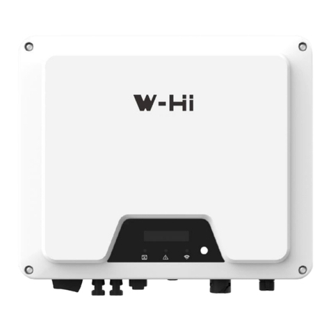
PowMr SOLXPOW X4 Series User manual

User Manual
SOLXPOW X4 Series
1


User Manual
SOLXPOW X4 Series
1
Important Safety Instructions
Please save these instructions for future use!
Read all of the instructions and cautions in the manual before beginning the installation!
⚫Before installation, please read this manual carefully and follow the instructions in this manual
strictly.
⚫Installers need to undergo professional training or obtain electrical related professional
qualification certificates.
⚫When installing, do not open the front cover of the inverter. Apart from performing work at the
wiring terminal (as instructed in this manual), touching or changing components without
authorization may cause injury to people, damage to inverters and annulment of the warranty.
⚫All electrical installations must conform to local electrical safety standards.
⚫If the inverter needs maintenance, please contact the local designated personnel for system
installation and maintenance.
⚫To use this inverter for power generation needs the permission of the local power supply
authority.
⚫The temperature of some parts of the inverter may exceed 60°C during operation. To avoid
being burnt do not touch the inverter during operation. Let it cool before touching it.
⚫When exposed to sunlight, the PV array generates dangerous high DC voltage. Please operate
according to our instructions, or it will result in danger to life.
⚫When wiring the lithium battery terminals, please disconnect the breaker or switch of the lithium
battery in case of a physical injury caused by the high voltage.
Inverter Storage
⚫Do not dispose of the original packing case. It is recommended to store the device in the original
packing case when the device is decommissioned.
⚫The storage temperature and humidity should be in the range of -30℃and+ 60℃, and less than
90%, respectively.
⚫If a batch of inverters needs to be stored, the height of each pile should be no more than 6
levels.

User Manual
SOLXPOW X4 Series
2
Symbols On the Inverter
Symbol
Description
To avoid the potential effects on the environment and human health as a
result of the presence of hazardous substances in electrical and electronic
equipment, end-users of electrical and electronic equipment should
understand the meaning of the crossed-out wheeled bin symbol. Do not
dispose of WEEE as unsorted municipal waste and have to collect such
WEEE separately.
Please read the instructions carefully before installation.
Do not touch any internal parts of the inverter being disconnected from the
mains, battery and PV input for 10 minutes.
CE mark, the inverter complies with the requirements of the applicable CE
guidelines.
Danger. Risk of electric shock!
The surface is hot during operation and do not touch.
Additional grounding point.
TÜV mark of conformity.

User Manual
SOLXPOW X4 Series
Table of Contents
Important Safety Instructions........................................................................................................... 1
Symbols On the Inverter............................................................................................................. 2
1 About This Manual ....................................................................................................................... 3
1.1 How To Use This Manual...................................................................................................... 3
1.2 Target Groups....................................................................................................................... 3
1.3 Symbols ............................................................................................................................... 3
1.4 Statement............................................................................................................................. 4
2 Product Description...................................................................................................................... 5
2.1 Product Introduction ............................................................................................................. 5
2.2 System Introduction.............................................................................................................. 5
2.3 Product Features.................................................................................................................. 6
2.4 Appearance.......................................................................................................................... 7
2.5 Indicator ............................................................................................................................... 8
3 Installation.................................................................................................................................... 9
3.1 Unpacking and Storage ........................................................................................................ 9
3.2 Packing List.......................................................................................................................... 9
3.3 Location...............................................................................................................................11
3.4 Mounting the Inverter.......................................................................................................... 13
4 Electrical Connection ................................................................................................................. 16
4.1 Electrical Wiring Diagram ................................................................................................... 17
4.2 AC Connection ................................................................................................................... 20
4.3 Monitoring Device Installation ............................................................................................. 25
4.4 Meter and CT Connection................................................................................................... 26
4.5 Communication Connection................................................................................................ 27
4.6 PV String Connection ......................................................................................................... 39
4.7 Power Cable of the Battery Connection .............................................................................. 43
5 Commissioning .......................................................................................................................... 46
5.1 App Preparation.................................................................................................................. 46
5.2 Inspection Before Commissioning....................................................................................... 46
5.3 Commissioning Procedure.................................................................................................. 46
5.4 Stop the Inverter................................................................................................................. 47

User Manual
SOLXPOW X4 Series
6 Operation................................................................................................................................... 48
6.1 Operation Modes................................................................................................................ 48
6.2 Back-Up and Off-Grid Output.............................................................................................. 52
6.3 Main Window...................................................................................................................... 53
6.4 General Setting .................................................................................................................. 54
6.5 Advanced Setting................................................................................................................ 56
6.6 Country Code (Safety Code) Setting................................................................................... 59
6.7 Auto-Test ............................................................................................................................ 59
6.8 Reactive Power .................................................................................................................. 61
7 Monitoring.................................................................................................................................. 64
7.1 Monitoring Device............................................................................................................... 64
7.2 Cloud monitoring App ......................................................................................................... 65
7.3 Local configuration App ...................................................................................................... 65
8 Technical Parameters................................................................................................................. 66
8.1 Table 1 Specifications for Grid or Generator Operation ....................................................... 66
8.2 Table 2: Inverter Mode Specifications (Backup Side) .......................................................... 68
8.3 Table 3 Specifications in Grid-Tie Mode (Grid-Side)............................................................ 70
8.4 Table 4 Specifications in Charging Mode ............................................................................ 72
8.5 Table 5 General Specifications ........................................................................................... 76
9 Troubleshooting ......................................................................................................................... 79
9.1 Error Message.................................................................................................................... 79
9.2 Protection........................................................................................................................... 82
9.3 Inverter Maintenance.......................................................................................................... 83
9.4 Battery Maintenance........................................................................................................... 84
10 Contact Information.................................................................................................................. 85

User Manual
SOLXPOW X4 Series
3
1 About This Manual
This manual is an integral part of PowMr SOLXPOW X4 series single-phase high-voltage hybrid
inverters (hereinafter referred to as the inverter). It mainly introduces the assembly, installation,
electrical connection, debugging, maintenance and troubleshooting of the products.
All or part of the products, services or features described in this document may not be within the
scope of purchase. This document serves only as a guide to use, and all statements, information
and recommendations in this document do not constitute any express or implied guarantee.
1.1 How To Use This Manual
Before installing and using inverters, please read this manual carefully, understand the safety
information and be familiar with the functions and characteristics of inverters.
The manual content of subsequent versions of the inverter may be subject to change. The latest
manual can be found at www.powmr.com.
1.2 Target Groups
This manual is applicable to electrical installers with professional qualifications and end-users, who
should have the following skills:
①Training for installation and commissioning of the electrical system, as well as dealing with
hazards.
②Knowledge of the manual and other related documents.
③Knowledge of the local regulations and directives.
1.3 Symbols
Important instructions contained in this manual should be followed during installation, operation and
maintenance of the inverter. They will be highlighted by the following symbols.
DANGER
Indicates a hazard with a high level of risk that, if not avoided, will result in
death or serious injury.
WARNING
Indicates a hazard with a medium level of risk that, if not avoided, could
result in death or serious injury.
CAUTION
Indicates a hazard with a low level of risk that, if not avoided, could
result in minor or moderate injury.
NOTICE
Indicates a situation that, if not avoided, could result in equipment or
property damage, data loss, equipment performance degradation.
NOTE
Indicates additional information, emphasized contents or tips that may be
helpful, e.g., to help you solve problems or save time.

User Manual
SOLXPOW X4 Series
4
1.4 Statement
Our company has the right not to undertake quality assurance in any of the following
circumstances:
⚫Damages caused by improper transportation.
⚫Damages caused by incorrect storage, installation or use.
⚫Damages caused by installation and use of equipment by non-professionals or untrained
personnel.
⚫Damages caused by failure to comply with the instructions and safety warnings in this
document.
⚫Damages of running in an environment that does not meet the requirements stated in this
document.
⚫Damages caused by operation beyond the parameters specified in applicable technical
specifications.
⚫Damages caused by unauthorized disassembly, alteration of products or modification of
software codes.
⚫Damages caused by abnormal natural environment (force majeure, such as lightning,
earthquake, fire, storm, etc.).
⚫Any damages caused by the process of installation and operation which don't follow the local
standards and regulations.
⚫Products beyond the warranty period.

User Manual
SOLXPOW X4 Series
5
2 Product Description
2.1 Product Introduction
The SOLXPOW X4 series inverter is also known as hybrid inverter or storage inverter, which is
mainly used to combine the PV array, lithium battery, loads and power grid to realize intelligent
power management and dispatching.
2.1.1 Models
The PowMr SOLXPOW X4 series hybrid inverter includes 7 models which are listed below:
SOLXPOW X4-25K, SOLXPOW X4-30K, SOLXPOW X4-36K, SOLXPOW X4-40K, SOLXPOW X4-
50K, SOLXPOW X4P-40K, SOLXPOW X4P-50K.
2.2 System Introduction
The hybrid solar system is usually composed of the PV array, hybrid inverter, lithium battery, loads
and power grid.
Figure 2-1 Schematic diagram of hybrid system

User Manual
SOLXPOW X4 Series
6
The applicable grid types for the SOLXPOW X4 series are TN-S, TN-C, TN-C-S and TT. When
applied to the TT grid, the voltage of N to PE suggests less than 30V.
Figure 2-2 Applicable grid types
2.3 Product Features
⚫Dual capabilities for both off-grid and grid-tied operation.
⚫Up to 50kW power output, enabling expanded energy storage.
⚫High efficiency of up to 98.8%.
⚫2/4 MPP trackers with a maximum of 30A/60A photovoltaic input per tracker, achieving a total
maximum PV input power of 75kW.
⚫Supports a maximum charge/discharge current of 100A.
⚫Wide battery voltage range from 140V to 750V.
⚫IP65 certified for high water and dust protection, suitable for both indoor and outdoor use.
⚫Supports parallel operation of up to 10 inverters.
⚫Plug-and-play terminals for convenient and rapid wiring.
⚫OLED display and app for configuration and data management.
⚫Equipped with a WiFi module for remote communication via a mobile app.
⚫Provides various protection functions, including DC reverse polarity protection, battery input
reverse protection, insulation resistance protection, surge protection, and more.
NOTICE
⚫The system is not suitable for supplying life-sustaining medical devices. It cannot guarantee
backup power in all circumstances.
SOLXPOW X4
SOLXPOW X4
SOLXPOW X4
SOLXPOW X4

User Manual
SOLXPOW X4 Series
7
2.4 Appearance
Figure 2-3 Inverter Appearance
Wiring terminals are at the bottom of the inverter, as shown in the table below.
Item
Terminal
Note
1
Display and LED panel
Display the operation information and working states of
the inverter.
2
Hanger
Used to hang the inverter on the wall-mounting bracket.
3
DC switch
Used to safely disconnect the DC circuit.
4
DC input terminal
PV connector (SOLXPOW X4-25~50K 8 pairs/ SOLXPOW
X4P-40~50K 6 pairs)
5
Battery input terminal
Battery connector
6
COM1 port
WiFi/LAN/4G module connector
7
COM2 port
Meter/BMS/RS485/DRED/DO Connector
8
COM3 port
DO/0-10V AO/4-20mA AO Connector
9
On-grid output terminal
Used for On-grid output cable connection
10
Back-up output terminal
Used for Back-up output cable connection
11
Generator input terminal
Generator connector(This function is temporarily
unavailable. Please contact PowMr if necessary)
1

User Manual
SOLXPOW X4 Series
8
2.5 Indicator
Figure 2-4 Inverter display interface
Item
Indicator
Status
Description
1
Grid Indicator
Off
Grid lost.
Slow
flashing
Inverter detected grid but not running in on-grid
mode.
Always on
Inverter works in on-grid mode.
2
Communication
Indicator
Green
Always on
The inverter communication is
running normally
Green
Flashing
The inverter communicates with
EMS or Master inverter through
RS485 or CAN.
Orange
Always on
The inverter isn’t communicating
with PowMr smart meter.
Red
Always on
The inverter isn’t communicating
with the BMS.
3
Display
Display off to save power, press the button to wake up the display.
5
Button
Switch display information and set parameters by short press or
long press.
1
4
2
3

User Manual
SOLXPOW X4 Series
9
3 Installation
3.1 Unpacking and Storage
The device is thoroughly tested and strictly inspected before delivery. Nonetheless, damage may
still occur during shipping. For this reason, please conduct a thorough inspection after receiving the
device.
Contact PowMr or the transport company in case of any damage or incompleteness, and provide
photos to facilitate services.
3.2 Packing List
The package of the inverter includes the following accessories. Please check whether the
accessories in the packing box are complete when receiving the goods.

User Manual
SOLXPOW X4 Series
10
Figure 3-1 Packing list
Item
Name and Quantity
A
Inverter (1pcs)
B
Inverter bracket (1pcs), Bolt assembly (4pcs), M6 screws (2pcs)
C
AC connector set (3 pcs)
D
PV terminal (SOLXPOW X4 8 pairs )
E
Battery terminal (1 pairs)
F
Meter with 3 CTs (1pcs)
G
COM2 connector set (1pcs)
H
COM3 connector set (1pcs)
I
Monitoring device (1pcs)
J
10m meter communication cable (1pcs), 3m battery communication cable (1pcs)
K
PE terminal(1pcs)
L
User guide

User Manual
SOLXPOW X4 Series
11
3.3 Location
The SOLXPOW X4 series inverters are designed with IP65 protection enclosure for indoor and
outdoor installations. When selecting an inverter installation location, the following factors should be
considered:
1. The wall on which the inverters mounted must be able to withstand the weight of the inverter.
2. The inverter needs to be installed in a well-ventilated environment.
3. Do not expose the inverter directly to strong sunlight to prevent excessive temperature
operation. The inverter should be installed in a place with shelter to prevent direct exposure to
sunlight and rain.
4. Install the inverter at eye level for easy inspection of screen data and further maintenance.
5. The ambient temperature of the inverter installation location should be between -30℃and 60℃.
6. The surface temperature of the inverter may reach up to 75℃. To avoid risk of burns, do not
touch the inverter while it's operating and inverter must be installed out of reaching of children.
3.3.1 Installation location
Select an optimal mounting location for safe operation, long service life and expected performance.
1. The inverter with protection rating IP65 can be installed both indoors and outdoors.
2. Install the inverter at a place convenient for electrical connection, operation, and maintenance.
Figure 3-2 Recommended installation location
WARNING
⚫Do not put flammable and explosive articles around the inverter.

User Manual
SOLXPOW X4 Series
12
3.3.2 Installation Spacing
Reserve enough clearance around the inverter to ensure sufficient space for heat dissipation.
Figure 3-3A Spacing for installing an inverter
In case of multiple inverters, reserve specific clearance between the inverters.
Figure 3-3B Spacing for installing multiple inverters
When installing inverters back-to-back, the distance between every two inverters should be at least
600 mm.
Figure 3-3C Spacing for Back to Back Installation

User Manual
SOLXPOW X4 Series
13
3.3.3 Installation Angle
Install the inverter vertically. Never install the inverter horizontally, or at forward/backward tilted, or
upside down.
Figure 3-4 Permitted and prohibited mounting positions
3.4 Mounting the Inverter
3.4.1 Bracket Installation
Dimensions of wall bracket (mm)
Figure 3-5 Dimensions of bracket
1. Level the assembled inverter-bracket by using the level, and mark the positions for drilling holes
on the mounting bracket. Drill the holes by using a hammer drill.

User Manual
SOLXPOW X4 Series
14
Figure 3-6 Marking hole position using installation bracket
2. Secure the inverter-bracket with bolts.
Figure 3-7 Fixing the bracket
3.4.2 Mounting the Inverter
Lift the inverter, hang the back rail on the fixed bracket carefully. Secure the inverter with M6
screws (two sides).
Figure 3-8 Mounting the inverter
3.4.3 External Ground Connection
Connect the inverter and ground bar through PE wire to achieve the purpose of grounding
protection. Please always remember wiring the PE wire before wiring other wires.
DANGER
⚫Do not connect the N-wire as a protective ground wire to the inverter casing. Otherwise, it
may cause electric shock.

User Manual
SOLXPOW X4 Series
15
Ground terminal connection steps:
1. The external grounding terminal is located in on the lower right side of the inverter.
2. Fix the grounding terminal to the PE wire with a proper tool and lock the grounding terminal to
the grounding hole in the lower right side of the inverter.
Figure 3-9 Grounding terminal connection
NOTICE
⚫Reliable grounding is good for resisting surge voltage shock and improving EMI performance.
⚫Inverters must be well-grounded.
⚫For a system with only one inverter, just ground the PE cable.
⚫For a multi-inverter system, all inverters PE wire need to be connected to the same
grounding copper bar to ensure equipotential bonding.

User Manual
SOLXPOW X4 Series
16
4 Electrical Connection
DANGER
⚫A high voltage in the conductive part of the inverter may cause an electric shock. When
installing the inverter, make sure that the AC and DC sides of the inverter are completely de-
energized.
⚫Do not connect the N-wire as a protective ground wire to the inverter casing. Otherwise, it
may cause electric shock.
WARNING
⚫Do not ground the positive or negative pole of the PV string, otherwise it will cause serious
damage to the inverter.
⚫Static may cause damage to the electronic components of the inverter. Antistatic measures
should be taken during installation and maintenance.
NOTICE
⚫Do not use other brands or other types of terminals other than the terminals in the accessory
package. PowMr has the right to refuse all damages caused by the mixed-use of terminals.
⚫Moisture and dust can damage the inverter, ensure the cable gland is securely tightened
during installation. The warranty claim will be invalidated if the inverter is damaged as a
result of a poorly connected cable connector.
This manual suits for next models
7
Table of contents
Other PowMr Inverter manuals

PowMr
PowMr POW-LVM5K-48V-N User manual
PowMr
PowMr POW-LVM3K-24V-H User manual
PowMr
PowMr SOLXPOW X2 Series User manual
PowMr
PowMr POW-SunSmart 8KE User manual
PowMr
PowMr POW-HPM Series User manual
PowMr
PowMr POW-HVM5.5M User manual

PowMr
PowMr SOLXPOW X1 Series User manual
PowMr
PowMr POW-SunSmart 8KL3 User manual
Popular Inverter manuals by other brands
Carmanah
Carmanah E Series user manual
Teledyne
Teledyne T3AFG5 Series user manual

Mitsubishi Electric
Mitsubishi Electric 800 Series instruction manual

Husky
Husky HSK065HD Owner's manual & warranty
Toshiba
Toshiba TOSVERT VF-S11 instruction manual
Movie Vision
Movie Vision MV-PI300A Installation and user guide

