Powrtran Tailfin Manual

INSTALLATION AND MAINTENANCE MANUAL

Love my Powrtran for my kicker.
Will have it on my boat from here
on out and every other shing boat
I will own in the future!
-John H.
“”

3
...to control your Kicker
INTRODUCTION
Thank you for your purchase of the most innovative
and user-friendly kicker steering system on the market.
In this manual, you will find step-by-step installation
instructions, as well as, maintenance tips and some basic
troubleshooting steps in the unlikely event of a failure.
Please read through all of the information carefully
before beginning your installation and if you have any
questions, please feel free to contact our technical service
department at 1-800-466-7697.
24253 COUNTY ROAD 7 ST. CLOUD, MN 56301
1-800-466-7697 WWW.POWRTRAN.COM
A DIVISION OF

4There’s nothing quicker...
TABLE OF CONTENTS
Introduction..............................................................................................3
Installation Instructions......................................................................5
Programming the System...............................................................26
Care and Maintenance......................................................................28
Troubleshooting..................................................................................30
Wiring Diagram...................................................................................32
iTroll..........................................................................................................33
Warranty................................................................................................34
Notes........................................................................................................36
About Us.................................................................................................38

5
...to control your Kicker
Tools Required
• Tape Measure • Adjustable Wrench • Permanent Marker
INSTALLATION STEPS
Failure to properly follow the installation steps WILL VOID
any and all warranty protection.
If you have any questions, please contact our Customer Service team at
1-800-466-7697. You can also email us at info@powrtran.com
ATTENTION!
STEP 1 Clean your outboard’s steer tube of debris with an air
compressor or with some canned air cleaner.

6There’s nothing quicker...
STARBOARD Application
PORT Application
STEP 2 Determine on which side of the outboard you will install
the Linkage. You need 9” of clearance on the Linkage
side and 7.5” of clearance on the Motor side.
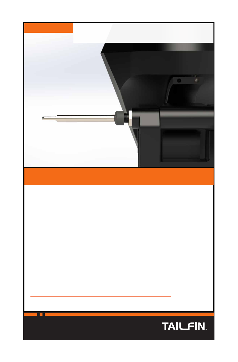
STEP 2 Remove the gray Wiper Nut from the Actuator.
9” 7.5”

7
...to control your Kicker
Note: For the purposes of this instruction, we
will show the STARBOARD application.
STEP 3 Slide the Actuator through the tilt tube so that the
threaded tab-end finishes on the side of the outboard
you will mount your Linkage to.
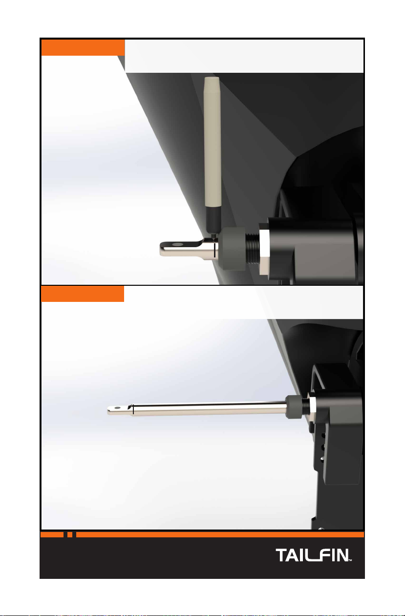
STEP 4 Insert the Wiper Nut over the Actuator and onto the
steer tube.

8There’s nothing quicker...
STEP 6 Twist the Wiper Nut onto the steer tube. You do not
need to use a tool to tighten the Wiper Nut but it should
be secure.
STEP 7 Twist the screw out a few inches.

9
...to control your Kicker
STEP 8 Slide the Motor over the Actuator coupler. Make sure
to line up the slot in the Motor shaft with the tab inside
the coupler.
STEP 9 Put pressure on the Actuator to keep the shafts
engaged as you twist the Motor onto the steer tube.

10 There’s nothing quicker...
STEP 10 Use an adjustable wrench to tighten the Motor in place.
The Motor is tight when you feel the bearing bottom
out inside the Motor cone.
STEP 11 Route the Motor cable down to your battery
compartment.

11
...to control your Kicker
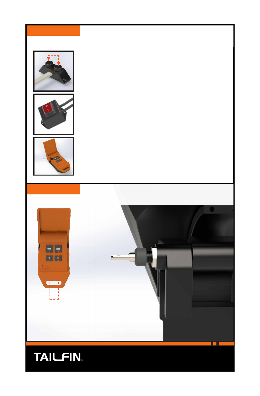
B.
A. C.
A. LED SWITCH
B. CONTROL HARNESS
C. POWER LEAD
STEP 12 Locate the three components of your Control Module.
STEP 13 Mount the Control Harness inside the battery box. The
Harness is supplied with industrial plastic VELCRO
which can be utilized for installation.

12 There’s nothing quicker...
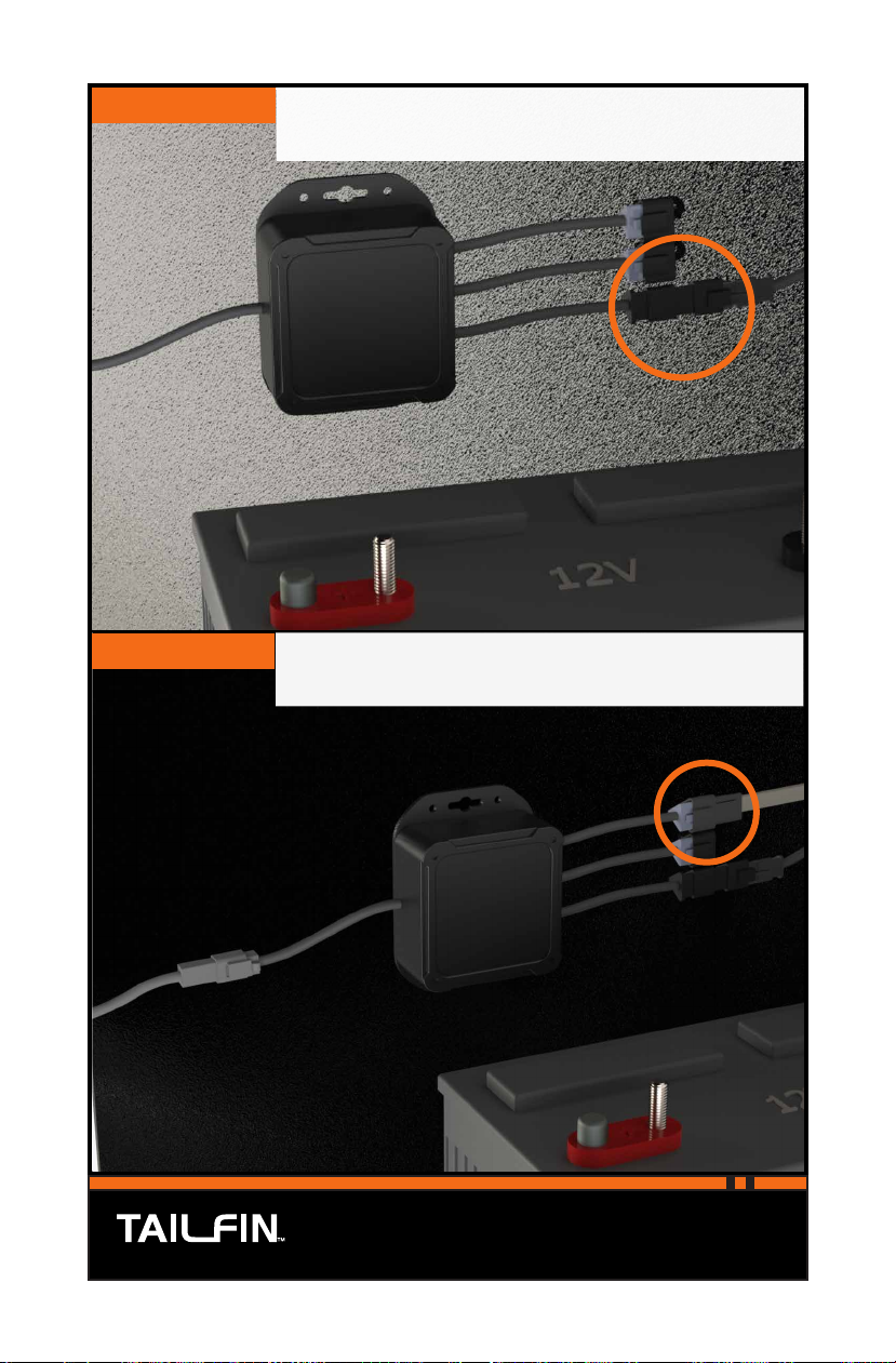
STEP 14 Plug the Motor cable into the Motor output on the
Control Harness.
STEP 15 Connect the Power Lead to the LED Switch.
13
...to control your Kicker
STEP 16 Connect the LED Switch to the Control Harness.
STEP 17 Connect the 24’ Corded Switch to one of the switch
inputs on the Control Module.
Note: The Module is supplied with two switch
inputs. This allows you to connect both your
24’ Corded Switch and an auxiliary throttle
controller if you choose to purchase one.
The switch inputs are shipped with plastic covers. These
covers MUST remain in place if an input is not being used.
14 There’s nothing quicker...
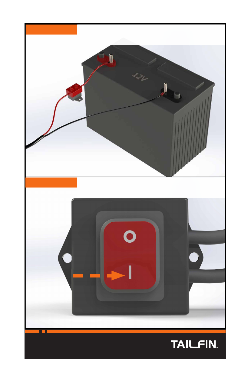
STEP 18 Connect the Control Module to your 12V battery.
STEP 19 Turn the system on by pressing the power button on
the LED switch. The LED will blink slowly to indicate
that the system is on and connected to power.
15
...to control your Kicker
STEP 20 Pair your Wireless Remote to your system.
STEP 21 Using your Wireless Remote, retract the actuator all the
way in.
Press and hold BOTH directional buttons on the 24’
Corded Switch for 5 seconds.
The LED Switch will go solid indicating the system is in
pairing mode.
Press and hold EITHER directional button on your Wireless
Remote for 1 second. When the LED Switch begins blinking
again, the Remote should be paired.
Note: Your installation will determine which
directional button you need to push to
retract the actuator. You can reverse how
the system responds by following directions
found on Pg. 27.
16 There’s nothing quicker...
STEP 22 With a permanent marker, mark the Actuator at the
point where it meets the Wiper Nut.
STEP 23 Use your Wireless Remote to extend the Actuator all
the way out.

17
...to control your Kicker
STEP 24 Mark the Actuator again at the point where it meets the
Wiper Nut.
STEP 25 Measure the distance between the marks you drew in
Steps 22 and 24. At the halfway point between those
two marks, draw a third mark on the Actuator.
18 There’s nothing quicker...
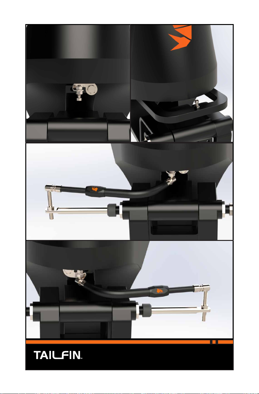
INSTALLING YOUR LINKAGE
Most outboard motors have two bolts located below the power head for
installing a tiller handle. The bracket supplied with the TAILFIN System is
designed to utilize one of these bolts. See Fig. A on Pg. 19.
On YAMAHA tiller motors, there is an arm coming across the front of the
motor with a vertical hole in the center. We supply all systems with a longer
Ball Stud to be mounted through this hole. Since the tiller bolts are not easily
accessible on these motors, utilizing the vertical hole is the recommended
installation point on YAMAHA tiller motors. See Fig B.
On the bottom of Pg. 19, you will find a diagram of how the Linkage is
mounted based on what side of the kicker motor you are installing it on.
Notice that the curved portion of the Linkage Arm will attach to the outboard
in either orientation.
NOTE: The Linkage Adjustment Nut is shipped with a protective covering in
place to guard the finish from marring while you are tightening it. Leave this
covering on until after you have made your final adjustments.
STEP 26 Retract the Actuator so that the mark you made in Step
25 meets the Wiper Nut.
19
...to control your Kicker
PORT-SIDE LINKAGE INSTALLATION
STARBOARD-SIDE LINKAGE INSTALLATION
A B

20 There’s nothing quicker...
Note: Do not tighten the 3/8” Nut
at this time. Once you have installed
and adjusted the Linkage arm
properly, you will use the 3/8” Nut
as a jam to keep the Stud in place.
STEP 27 Position your outboard so it is facing straight forward.
This ensures that when the Linkage is attached, the
motor will have even turning in both directions.
STEP 28 Twist the long Quick-Connect Stud into the threaded
hole in the tab-end of the Actuator. The 3/8” Nut will
be on the top-side of the tab.
Other manuals for Tailfin
1
Table of contents
Other Powrtran Fishing Equipment manuals

Popular Fishing Equipment manuals by other brands

Alvey
Alvey REEF QUEEN Instructions for use

Toslon
Toslon TFL40 quick start guide

Fiap
Fiap Pendulum Feeder 1550 manual

Jaxon
Jaxon XTR CARP SENSITIVE PLUS Operation manual

Offshore Angler
Offshore Angler GOLD CUP GCP-10 Operation instructions

FISHING SPECIALTIES
FISHING SPECIALTIES Bowducer installation instructions


