Powrtran Tailfin Manual

TAIL FIN
TM
REMOTE KICKER STEERING SYSTEM
INSTALLATION AND MAINTENANCE MANUAL

Love my Powrtran for my kicker.
Will have it on my boat from here
on out and every other shing boat
I will own in the future!
-John H.
“”

3
...to control your kicker
TAIL FIN
TM
INTRODUCTION
Thank you for your purchase of the most innovative
and user-friendly kicker steering system on the market.
In this manual, you will find step-by-step installation
instructions, as well as, maintenance tips and some basic
troubleshooting steps in the unlikely event of a failure.
Please read through all of the information carefully
before beginning your installation and if you have any
questions, please feel free to contact our technical service
department at 1-800-466-7697.
24253 COUNTY ROAD 7 ST. CLOUD, MN 56301
1-800-466-7697 WWW.POWRTRAN.COM
A DIVISION OF

4There’s nothing quicker...
TAIL FINTM
TABLE OF CONTENTS
Introduction..............................................................................................3
Installation Instructions......................................................................5
Programming the System...............................................................36
Care and Maintenance......................................................................38
Troubleshooting...................................................................................40
Wiring Diagram...................................................................................42
iTroll..........................................................................................................43
Warranty................................................................................................44
About Us.................................................................................................46

5
...to control your kicker
TAIL FIN
TM
Tools Required
• Tape Measure
• Permanent Marker
• Phillips Screwdriver
• Adjustable Wrench
• 3/16” Allen Wrench
• 9/16” Wrench
• 5/8” Wrench
• 1/2” Wrench
• Air Compressor
INSTALLATION STEPS
STEP 1
Use an air nozzle to clean
the steer tube of any
debris.
Failure to properly follow the installation steps WILL
VOID any and all warranty.
ATTENTION!
6There’s nothing quicker...
TAIL FINTM
STEP 2
Determine which side of the kicker motor you will mount the
motor on and which side you will mount the linkage arm on.
NOTE: You need 7.5” of clearance on the motor side and 9” of
clearance on the linkage side.
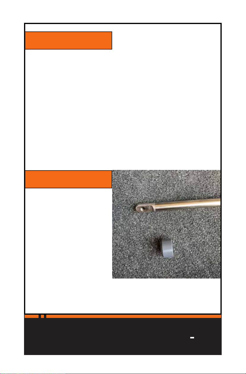
STEP 3
Locate the actuator
assembly and remove the
grey wiper nut from the
actuator.
7
...to control your kicker
TAIL FIN
TM
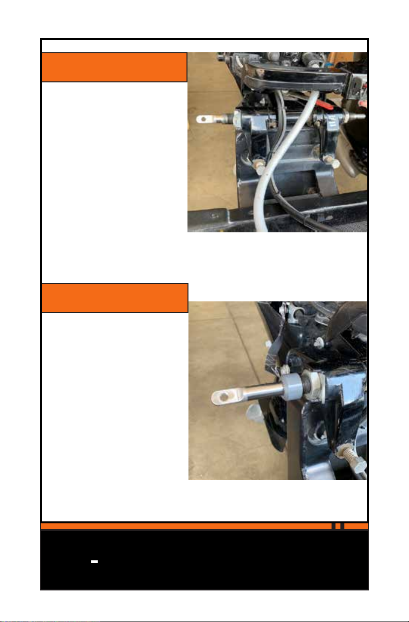
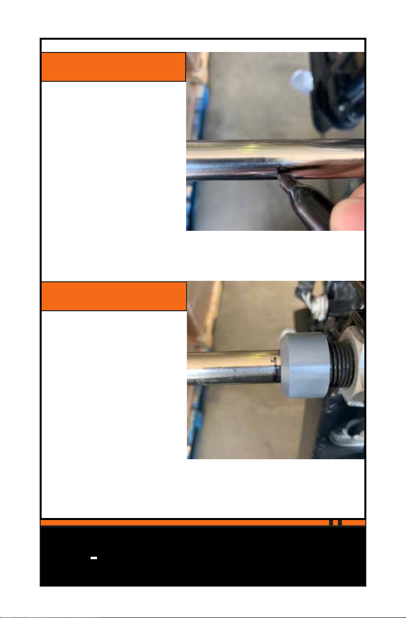
STEP 5
Slide the wiper nut over
the end of the actuator
and screw it onto the
steer tube.
STEP 4
Slide the tab-end of the
actuator through the
steer tube so that it
ends up on the side of
the kicker that you are
mounting the linkage.
8There’s nothing quicker...
TAIL FINTM
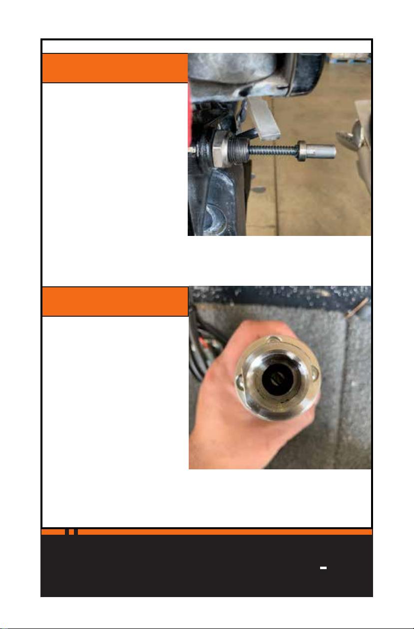
STEP 6
Twist the actuator screw
out a few turns. You do
not have to extend the
actuator all the way out;
you just want to have
some space to install the
motor onto the actuator
coupler.
STEP 7
Locate the motor. There is
a slot in the motor shaft
which will engage with
the tab in the end of the
actuator coupler.
9
...to control your kicker
TAIL FIN
TM
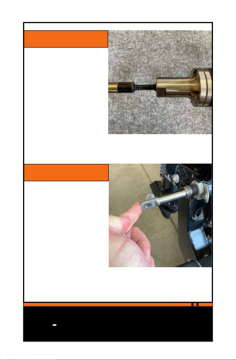
STEP 8
Slide the motor mount
over the coupler, ensuring
that the motor shaft
engages the actuator tab.
STEP 9
Apply light pressure
to the other end of the
actuator to keep the
motor shaft engaged as
you twist the motor onto
the steer tube.

10 There’s nothing quicker...
TAIL FINTM
STEP 10
Twist the motor onto the
steer tube until it is hand-
tight.
STEP 11
Use an adjustable wrench
to tighten the motor
another quarter-turn.
11
...to control your kicker
TAIL FIN
TM
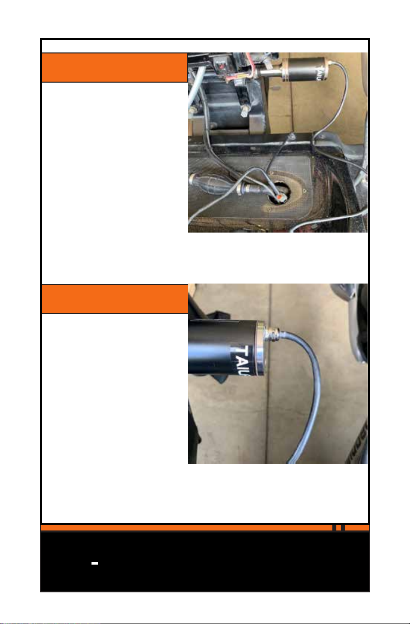
STEP 12
Route the motor cable to
the battery compartment.
STEP 13
The motor cable MUST be
allowed a gradual bend.
Pinching or stressing the
cable can lead to fatigue
and possible failure.
12 There’s nothing quicker...
TAIL FINTM
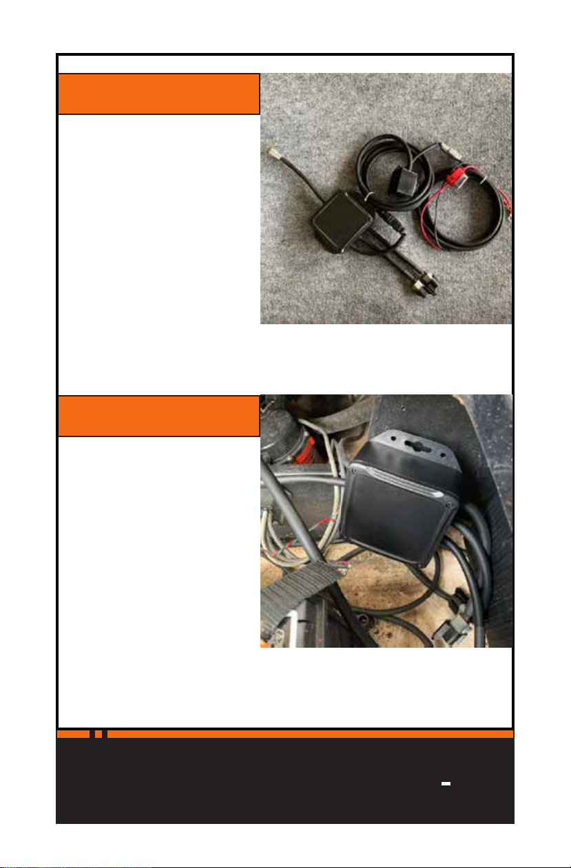
STEP 15
Mount your Relay
Control in the battery
compartment. Make sure
to mount it where the
power leads can reach
your desired battery.
NOTE: The box is
waterproof but should
still be mounted in such
a way that it can stay as
dry as possible.
STEP 14
Locate your Relay Control
Assembly. The relay is
shipped fully assembled.
If you need to disconnect
any cables for installa-
tion, please refer to the
wiring diagram on Pg.42.

13
...to control your kicker
TAIL FIN
TM
STEP 16
Connect the POSITIVE (+)
power lead from the Relay
Control.
STEP 17
Connect the NEGATIVE (-)
power lead from the Relay
Control.

14 There’s nothing quicker...
TAIL FINTM
STEP 18
Locate the LED Switch
Box. The LED is used
in programming and
troubleshooting, as
well as, serving as the
ON/OFF switch for the
system. Mount the LED
wherever you wish.
STEP 19
Make sure the LED is in
the ON position. The LED
will blink at a slow steady
pace, indicating it is on
and the power has been
connected.

15
...to control your kicker
TAIL FIN
TM
STEP 20
Using your wireless
remote, retract the
actuator in as far as it will
go.
STEP 21
Use a permanent marker
to draw a mark on the
actuator where it meets
the wiper nut.

16 There’s nothing quicker...
TAIL FINTM
STEP 22
Using your remote,
extend the actuator as
far out as it will go.
STEP 23
Use your permanent
marker to mark the
actuator where it meets
the wiper nut.
17
...to control your kicker
TAIL FIN
TM
STEP 25
Retract the actuator until
the mark you made in
Step 24 meets the wiper
nut.
STEP 24
Measure the distance
between the marks you
made in Steps 21 and 23
and mark the actuator at
the centerpoint of the two
marks.
18 There’s nothing quicker...
TAIL FINTM
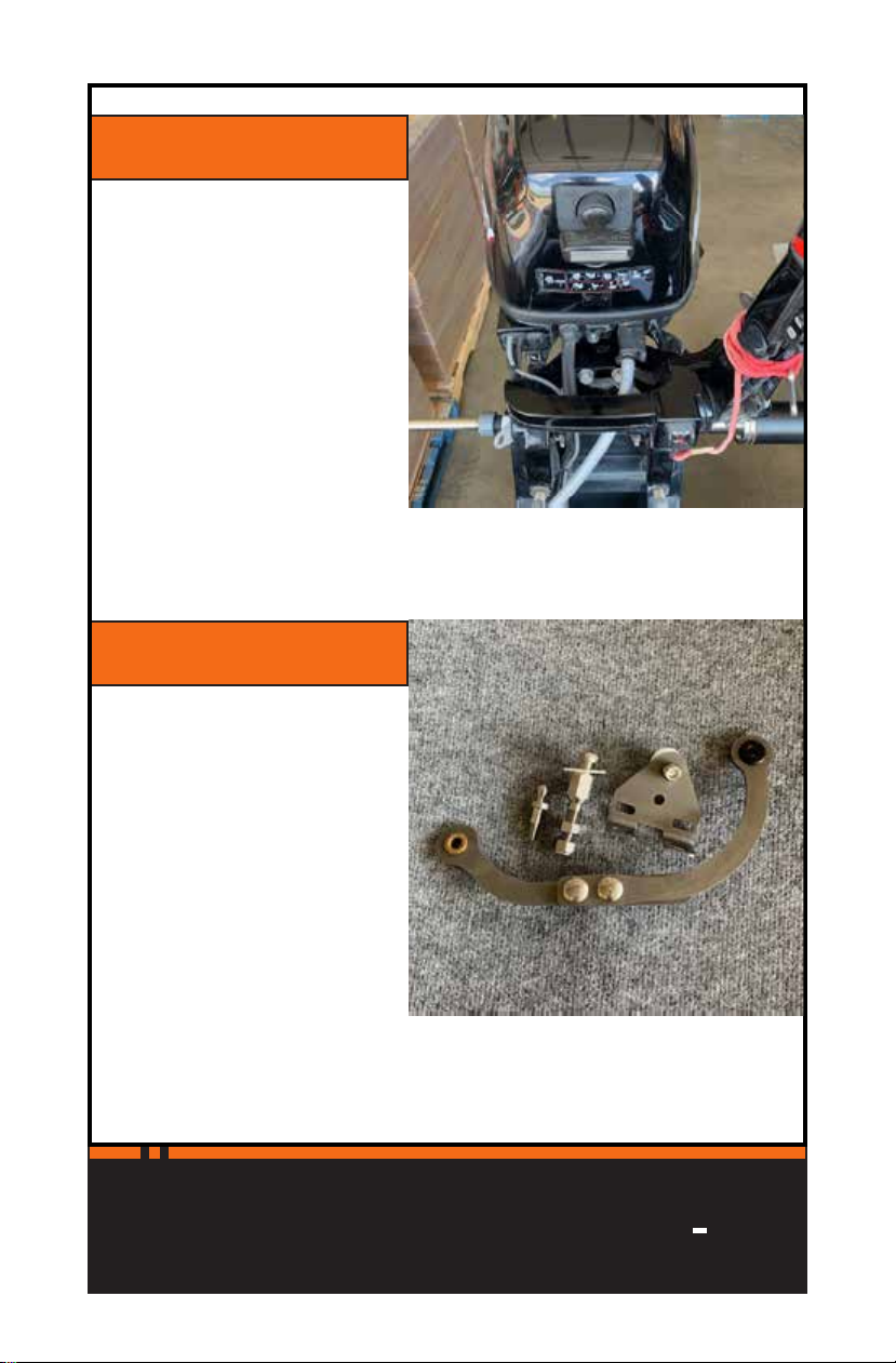
STEP 26
Position the outboard
so it is facing straight
forward.
STEP 27
Locate your fit kit.

19
...to control your kicker
TAIL FIN
TM
INSTALLING YOUR LINKAGE
The next few pages will show diagrams on how the
linkage arms should be assembled depending on the Kit
and orientation you are installing.
A few important notes on linkage installation:
• Due to variations between different motor
manufacturers, you may need to alter how you
install the bracket. It may need to be flipped, or you
may have to use different holes, but the bracket is
designed to fit as many models as possible. What will
be shown in the steps is the most common linkage
configuration. It is meant to show you the basics of
the linkage install.
• It may be possible to avoid installing the braket
altogether if you are using our quick-disconnect
option. An example of this is Yamaha tiller motors
which have a hole in the center of the grab-handle.
Our Fit Kit A includes a longer ball-stud designed to fit
through this hole.
• Similarly, if your motor has a ball-stud installed
previously from a tie-bar, it may be possible to use
that stud with our quick-disconnect linkage.
The most important thing to remember when
installing your linkage is to keep the mounting
point as close as possible to the center of the
outboard.

20 There’s nothing quicker...
TAIL FINTM
FIT KIT A
PORT-SIDE LINKAGE STANDARD APPLICATION
Other manuals for Tailfin
1
Table of contents
Other Powrtran Fishing Equipment manuals


