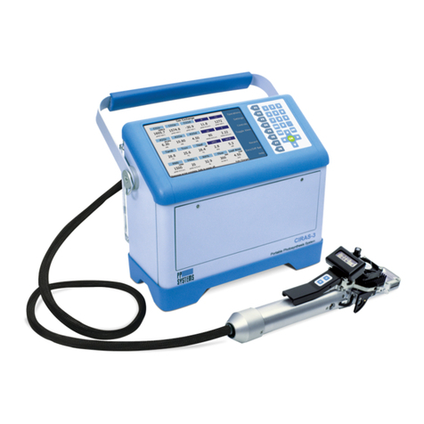
PP Systems TARGAS-1 Installation manual

TARGAS-1 Operation Manual V. 1.02 2 support@ppsystems.com
Contents
Welcome .......................................................................................................................................................9
User Registration.....................................................................................................................................10
Service & Warranty..................................................................................................................................10
Contact Information.................................................................................................................................10
Unpacking and Storage of Your Equipment............................................................................................11
Storage – Transport Case ................................................................................................................11
Powering up the TARGAS-1 for the First Time.......................................................................................11
Data Storage ...........................................................................................................................................12
Technical Specification ...............................................................................................................................12
TARGAS-1 CO2/H2O Gas Analyzer (Main Console)...............................................................................12
PLC5 Leaf Cuvette..................................................................................................................................13
Light Unit (Optional).................................................................................................................................14
Summary of System Design........................................................................................................................14
Overview and Theory ..............................................................................................................................14
System Components for Measurement of Leaf Gas Exchange..................................................................16
TARGAS-1 CO2/H2O Gas Analyzer ........................................................................................................16
PLC5 Leaf Cuvette..................................................................................................................................17
Light Unit (Optional)..........................................................................................................................17
External Sensors/Chambers for Use with TARGAS-1 ............................................................................17
Quantum Sensor...............................................................................................................................17
TRP-3 Temperature/PAR Probe.......................................................................................................18
SRC-2 Soil Respiration Chamber.....................................................................................................18
CPY-5 Canopy Assimilation Chamber..............................................................................................19
STP-2 Soil Temperature Probe ........................................................................................................19
Getting Familiar with the TARGAS-1 Portable Photosynthesis System.....................................................20
TARGAS-1 Portable CO2/H2O Gas Analyzer (Main Console) ................................................................20
Back of TARGAS-1..................................................................................................................................22
PLC5 Leaf Cuvette ..................................................................................................................................23
Light Unit (Optional)..........................................................................................................................23
Quick Start...................................................................................................................................................24
Leaf Gas Exchange Measurements – Recommended Set-up ...................................................................26
When should I record a measurement?..................................................................................................26
Schematic of TARGAS-1 Portable Photosynthesis System Air Supply System.....................................27
Routine System Checks Before Starting.....................................................................................................28

TARGAS-1 Operation Manual V. 1.02 3 support@ppsystems.com
System Power.............................................................................................................................................29
Battery Specification................................................................................................................................29
Power Supply/AC Adapter Rating: ..........................................................................................................29
TARGAS-1 Main Console Components......................................................................................................30
Touch Display..........................................................................................................................................30
Navigation using the Touch Display .................................................................................................30
Power Switch...........................................................................................................................................30
Ext Power Jack........................................................................................................................................31
Ext Power LED ........................................................................................................................................31
Probe Ports..............................................................................................................................................31
PLC Gas Ports.........................................................................................................................................31
Gas Ports.................................................................................................................................................32
Flow Rate..........................................................................................................................................32
USB Flash Drive Port ..............................................................................................................................32
USB PC Port............................................................................................................................................32
Absorber Columns...................................................................................................................................33
Auto-Zero Column ............................................................................................................................33
Molecular Sieve ................................................................................................................................33
Molecular Sieve Repackaging..........................................................................................................34
CO2& H2O Control Columns............................................................................................................34
Soda Lime.........................................................................................................................................34
Drierite ..............................................................................................................................................35
Foam Filters......................................................................................................................................36
Absorber Filters ................................................................................................................................36
“O” Rings ..........................................................................................................................................36
TARGAS-1 Menu Overview (Flow Chart) ...................................................................................................37
Splash Screen.............................................................................................................................................37
General Screen Info....................................................................................................................................39
Measure Screen Info...............................................................................................................................39
Parameters in Parenthesis ......................................................................................................................39
Heartbeat and Display Update Rate:.......................................................................................................40
Data Entry Screen ...................................................................................................................................40
Measurement Mode ....................................................................................................................................41
Measure Screen 1...................................................................................................................................41
Measure Screen 2...................................................................................................................................43

TARGAS-1 Operation Manual V. 1.02 4 support@ppsystems.com
Graphic Display Screen...........................................................................................................................43
Alternative Measurement Screens..............................................................................................................45
Diff Mode .................................................................................................................................................45
Measure Screen 1 ............................................................................................................................45
Measure Screen 2 ............................................................................................................................45
Graphic Display Screen....................................................................................................................46
Closed or Absolute Mode........................................................................................................................47
Measure Screen 1 ............................................................................................................................47
Measure Screen 2 ............................................................................................................................47
Graphic Display Screen....................................................................................................................48
Direct Link Settings .....................................................................................................................................49
CO2r Setting............................................................................................................................................49
H2Or Setting............................................................................................................................................49
PARi Setting ............................................................................................................................................50
Flow Setting.............................................................................................................................................50
TLeaf Setting ...........................................................................................................................................51
Area Setting.............................................................................................................................................51
Main Menu...................................................................................................................................................52
Settings....................................................................................................................................................52
Settings 1 Menu.......................................................................................................................................52
Device Mode Settings.......................................................................................................................53
RB Setting.........................................................................................................................................54
RS Factor Setting .............................................................................................................................55
Zero Settings ....................................................................................................................................55
Graph Setting....................................................................................................................................57
Reset Zero Absorber ........................................................................................................................57
Settings 2 Menu.......................................................................................................................................58
Alarm Sound Setting.........................................................................................................................58
Averaging Setting .............................................................................................................................59
Interval Settings................................................................................................................................59
TARGAS ID Setting..........................................................................................................................60
Settings 3 Menu.......................................................................................................................................60
Probe Port Settings...........................................................................................................................61
Ref On Time Setting.........................................................................................................................62
An On Time Setting ..........................................................................................................................62

TARGAS-1 Operation Manual V. 1.02 5 support@ppsystems.com
Alarm Settings ..................................................................................................................................63
Sample Flow Setting.........................................................................................................................63
Settings 4 Menu.......................................................................................................................................64
Host Port Setting...............................................................................................................................64
Reset WiFi Settings..........................................................................................................................65
WiFi Power Setting...........................................................................................................................65
Set Clock Settings ............................................................................................................................66
Default Settings ................................................................................................................................66
Ship Mode Settings...........................................................................................................................67
Processes....................................................................................................................................................69
SRC (Soil Respiration Chamber) Process ..............................................................................................69
Connecting the SRC-2 Soil Respiration Chamber to the TARGAS-1 ..............................................69
SRC – Start Process (Step 1)...........................................................................................................70
SRC – Volume and Area Settings (Step 2) ......................................................................................70
SRC – Termination Settings (Step 3) ...............................................................................................71
SRC – Other Settings (Step 4) .........................................................................................................71
SRC Flushing (Step 5)......................................................................................................................72
SRC – Start Measuring (Step 6).......................................................................................................72
Data Plot Screen (Step 7).................................................................................................................73
For more information on the theory and calculation of soil respiration/canopy assimilation, please
refer to Mass Flow............................................................................................................................74
Transpiration.....................................................................................................................................74
Leaf Temperature .............................................................................................................................75
Saturation Vapor Pressure ...............................................................................................................76
Stomatal Conductance .....................................................................................................................76
Net Photosynthesis...........................................................................................................................77
Intercellular CO2Concentration........................................................................................................77
Definition of Symbols and Physical Constants Used in Equations...................................................78
References .......................................................................................................................................79
CPY (Canopy Assimilation Chamber) Process.......................................................................................80
Connecting the CPY-5 Canopy Assimilation Chamber to the TARGAS-1.......................................80
CPY – Start Process (Step 1)...........................................................................................................80
CPY – Volume and Area Settings (Step 2).......................................................................................81
CPY – Termination Settings (Step 3) ...............................................................................................82
CPY – Other Settings (Step 4) .........................................................................................................82
CPY – Prepare Chamber (Step 5)....................................................................................................83

TARGAS-1 Operation Manual V. 1.02 6 support@ppsystems.com
CPY – Start Measuring (Step 6).......................................................................................................83
CPY Data Plot Screen (Step 7) ........................................................................................................84
For more information on the theory and calculation of soil respiration/canopy assimilation, please
refer to Mass Flow............................................................................................................................85
Transpiration.....................................................................................................................................85
Leaf Temperature .............................................................................................................................86
Saturation Vapor Pressure ...............................................................................................................87
Stomatal Conductance .....................................................................................................................87
Net Photosynthesis...........................................................................................................................88
Intercellular CO2Concentration........................................................................................................88
Definition of Symbols and Physical Constants Used in Equations...................................................89
References .......................................................................................................................................90
Custom Process......................................................................................................................................91
Custom – Start Process (Step 1)......................................................................................................91
Custom – Volume and Area Settings (Step 2)..................................................................................92
Custom – Termination Settings (Step 3) ..........................................................................................92
Custom – Other Settings (Step 4) ....................................................................................................93
Custom – Prepare Chamber (Step 5)...............................................................................................94
Custom – Start Measuring (Step 6)..................................................................................................94
Custom Data Plot Screen (Step 7) ...................................................................................................95
Injection Process .....................................................................................................................................96
Measurement Principle.....................................................................................................................96
Sample Injection Kit (Part No. ACS037)...........................................................................................97
Injection – Start Process (Step 1).....................................................................................................98
Injection – Settings (Step 2) .............................................................................................................98
Injection – Sample Setting (Step 3)..................................................................................................99
Injection - Zero (Step 4)....................................................................................................................99
Injection – Baseline Phase (Step 5) ...............................................................................................100
Injection – Injection Phase (Step 6)................................................................................................101
Information Menu......................................................................................................................................102
About .....................................................................................................................................................103
Contact ..................................................................................................................................................103
Calibration.................................................................................................................................................104
CO2Calibration......................................................................................................................................104
Connecting Calibration Gas to the TARGAS-1 ..............................................................................105
H2O Calibration......................................................................................................................................107

TARGAS-1 Operation Manual V. 1.02 7 support@ppsystems.com
Connecting Dew Point Generator to the TARGAS-1......................................................................108
Touch Calibration ..................................................................................................................................110
PAR .......................................................................................................................................................110
Light Unit Calibration.............................................................................................................................112
Diagnostics................................................................................................................................................114
CO2 IRGA Diagnostics..........................................................................................................................115
H2O IRGA Diagnostics..........................................................................................................................116
Battery Diagnostics................................................................................................................................117
CO2 Zeros Diagnostics .........................................................................................................................117
H2O Zeros Diagnostics .........................................................................................................................118
Advanced Diagnostics...........................................................................................................................118
Data Storage.............................................................................................................................................119
USB Flash Drive (Memory Stick)...........................................................................................................119
Data Storage Format.............................................................................................................................120
Data Storage/Measure Format Table .......................................................................................................121
Measure Extension Code Format Tables..............................................................................................121
Digital Connection Methods......................................................................................................................125
USB .......................................................................................................................................................125
Wireless.................................................................................................................................................125
Digital Communication Protocols and Software....................................................................................125
TARGAS-1 Command Set........................................................................................................................125
TARGAS-1 Auto Strings........................................................................................................................127
TARGAS-1 Command Set Table ..........................................................................................................128
Get/Set Parameter Values Table ..........................................................................................................132
GAS (Gas Analysis Software)...................................................................................................................136
Error Messages.........................................................................................................................................138
Maintenance..............................................................................................................................................140
External Air Filter...................................................................................................................................140
Absorber Columns and Desiccants.......................................................................................................141
Gray Foam Filters...........................................................................................................................141
Absorber Filters ..............................................................................................................................141
End Cap “O” Rings .........................................................................................................................141
Soda Lime.......................................................................................................................................141
Drierite ............................................................................................................................................142
Molecular Sieve ..............................................................................................................................142

TARGAS-1 Operation Manual V. 1.02 8 support@ppsystems.com
Molecular Sieve Repackaging........................................................................................................143
Foam Filters....................................................................................................................................144
Absorber Filters ..............................................................................................................................144
“O” Rings ........................................................................................................................................144
Access to Internal Components ............................................................................................................144
Hydrophobic Filters.........................................................................................................................145
Battery.............................................................................................................................................146
Pumps.............................................................................................................................................146
Infrared Source...............................................................................................................................146
PLC5 Leaf Cuvette................................................................................................................................147
Replacement of leaf gaskets ..........................................................................................................147
Checking for Leaks Associated with the PLC5...............................................................................148
PLC5 Gas Connector......................................................................................................................149
PAR Sensor....................................................................................................................................149
Light Unit.........................................................................................................................................149
Appendix 1. Photosynthesis Equations Used in TARGAS-1....................................................................150
Mass Flow.......................................................................................................................................150
Transpiration...................................................................................................................................150
Leaf Temperature ...........................................................................................................................151
Saturation Vapor Pressure .............................................................................................................152
Stomatal Conductance ...................................................................................................................152
Net Photosynthesis.........................................................................................................................152
Intercellular CO2Concentration......................................................................................................153
Definition of Symbols and Physical Constants Used in Equations.................................................154
References .....................................................................................................................................155
Appendix 2. Soil CO2Efflux and Net Canopy CO2Flux...........................................................................156
Theory....................................................................................................................................................156
Correction for water vapor increase on CO2efflux.........................................................................158
FCO2Units for measurement of Soil CO2Efflux ............................................................................158
References .....................................................................................................................................159

TARGAS-1 Operation Manual V. 1.02 9 support@ppsystems.com
Welcome
Thank you very much for purchasing our TARGAS-1 Portable Photosynthesis System. Although the
majority of customers will be using this system for measurement of leaf gas exchange using our PLC5
Leaf Cuvette, it can also be used with a number of additional chambers and accessories for
measurement of soil respiration, net canopy flux, PAR, soil temperature, soil moisture and soil
temperature and temperature/PAR. The TARGAS-1 can also be used as a stand-alone CO2/H2O gas
analyzer in both absolute and differential mode. We greatly appreciate your business and we look
forward to working with you and your research team for many years to come.
This manual and the information contained within are copyrighted to PP Systems. No part of the
manual may be copied, stored, transmitted or reproduced in any way or by any means including,
but not limited to, photocopying, photography, magnetic or other mechanical or electronic means,
without the prior written consent of PP Systems, Inc.
For applications where failure of this equipment to function correctly would lead to consequential damage,
the equipment must be checked for correct operation and calibration at intervals appropriate to the

TARGAS-1 Operation Manual V. 1.02 10 support@ppsystems.com
circumstances. The PP Systems' equipment warranty is limited to replacement of defective components,
and does not cover injury to persons or property or other consequential damage.
This manual is provided to help you install and operate the equipment. Every effort has been made to
ensure that the information it contains is accurate and complete. PP Systems does not accept any liability
for losses or damages resulting from the use of this information.
It is the operator’s responsibility to review this information prior to installation and operation of the
equipment. Otherwise, damage may be caused which is not covered under our normal warranty policy.
PP Systems is a registered trademark of PP Systems, Inc. All brand names are trademarks or registered
trademarks of their respective owners.
User Registration
It is very important that ALL new customers register themselves with us to ensure that our user’s list is
kept up-to-date. If you are a PP Systems’ user, please go to www.ppsystems.com and click on Customer
Registration in the upper left hand corner.
Only REGISTERED users will be allowed access to the protected “Users” section of our web site. This
section will contain important product information including hardware/software updates, application notes,
newsletters, etc.
Thank you in advance for your cooperation.
Service & Warranty
PP Systems' equipment warranty is limited to replacement of defective components, and does not cover
injury to persons or property or other consequential damage.
The equipment is covered under warranty for one complete year, parts and labor included. This, of
course, is provided that the equipment is properly installed, operated and maintained in accordance with
written instructions (i.e. Operator's Guide).
The warranty excludes all defects in equipment caused by incorrect installation, operation or
maintenance, misuse, alteration, and/or accident.
If for some reason, a fault is covered under warranty, it is the responsibility of the customer to return the
goods to PP Systems or an authorized agent for repair or replacement of the defective part(s).
Prior to returning equipment to PP Systems for service, you must first get in contact with our Service
Manager (service@ppsystems.com) to request a case number for reference and tracking purposes.
Contact Information
PP Systems, Inc.

TARGAS-1 Operation Manual V. 1.02 11 support@ppsystems.com
110 Haverhill Rd, Suite 301
Amesbury, MA 01913 USA
Tel: 978-834-0505 Fax: 978-834-0545
Sales: sales@ppsystems.com
Support: support@ppsystems.com
Service: service@ppsystems.com
URL: www.ppsystems.com
Unpacking and Storage of Your Equipment
It is extremely important that you check the contents of your equipment immediately upon receipt to
ensure that your order is complete and that it has arrived safely. Please refer to the packing list to show
all items that are included with your order. DO NOT DISCARD ANY OF THE PACKAGING MATERIAL
UNTIL ALL OF THE ITEMS LISTED ARE ACCOUNTED FOR. WE RECOMMEND THAT YOU RETAIN
THE ORIGINAL PACKING FOR FUTURE USE. If you suspect that any of the items listed on the packing
list are not included or damaged, you must contact PP Systems or your authorized distributor
immediately.
Storage – Transport Case
We highly recommend storing your equipment in a safe, dry location. Every
system is supplied with a custom designed transport case which is ideal for both
transporting and storage of your system. The transport case allows for storage
of:
•TARGAS-1 Console
•PLC5 Leaf Cuvette and Light Unit
•Air Supply Intake Unit
•Extra compartment for spares
Powering up the TARGAS-1 for the First Time
When you first receive your new TARGAS-1 from PP Systems you will need to first connect it up to the
external power supply/charger prior to powering up the instrument. To avoid accidental power up during
shipment we put the instrument into “Ship Mode” (see Ship Mode Settings on page 67 for more
information).
Therefore, when you are ready to begin:

TARGAS-1 Operation Manual V. 1.02 12 support@ppsystems.com
1. Locate the power supply/charger and power cord inside the packing box.
2. Connect the AC power cord to the mains and the barrel connector into the EXT Power socket on
the back of the TARGAS-1.
3. Press the ON/OFF switch to power up the instrument. The power switch should now have an
illuminating blue ring indicating power is on.
4. Allow 10-15 minutes to achieve warm-up.
You are ready to go!
Data Storage
For convenience and ease it is very important to note that all TARGAS-1 system data is recorded and
saved directly to a USB flash drive (i.e. memory stick or thumb drive). A USB flash drive is included in the
spares kit (Part No. 43034-1) with every new system. Most commercially available flash drives are
compatible with the TARGAS-1.
THEREFORE IT IS IMPERATIVE THAT YOU HAVE A USB FLASH DRIVE WITH YOU AT ALL TIMES
IF YOU WANT TO RECORD DATA WITH YOUR TARGAS-1. OTHERWISE DATA WILL HAVE TO BE
RECORDED MANUALLY.
Technical Specification
TARGAS-1 CO2/H2O Gas Analyzer (Main Console)
Analysis Method
Two non-dispersive infrared, configured as an absolute absorptiometer
with microprocessor control of linearization for both CO2and H2O. All
readings are automatically corrected for temperature, pressure and foreign
gas broadening.
CO
2
Measurement
Ranges
0 ‐ 10000 μmol mol‐1
Precision: 1 μmol mol‐
1
H
2
O Range
0‐75 mb
Precision: 0.1 mb
Pressure
Compensation Range
80-115 kPa
Absolute Accuracy
< 1% of span concentration over the calibrated range but limited by the
accuracy of the calibration mixture.
Differential Accuracy
± 1 μmol mol‐1for CO2differential up to 50 μmol mol‐1

TARGAS-1 Operation Manual V. 1.02 13 support@ppsystems.com
Linearity
< 1% throughout the range
Stability
Auto-zero at regular intervals corrects for sample cell contamination,
source and detector ageing and changes in electronics.
Calibration
User programmable calibration (if required)
Warm-up Time
Approximately 15 minutes
Sampling Rate
10 Hz. Sample data is averaged and output every 1.0 seconds.
Sample Flow Rate
50-200 cc/min. An internal, electronic flow sensor monitors flow rate.
Air Supply Unit
Integral pump for supply of reference air to the leaf cuvette
Range: 200-500 cc/min
CO2and H2O Control
User adjustable from 0-100% of ambient.
Sampling Pump
Integral pump for sample (analysis) air
Range: 50-200 cc/min
An internal electronic flow sensor monitors flow rate.
Sampling Rate
10 Hz. Sample data is averaged and output every 1.0 second.
Digital Output
USB
Gas Flow Rate
200-500 cc/min (280-340 cc/min is optimal). An electronic flow sensor
monitors flow rate.
Terminal Block
10 pin terminal block for system inputs and outputs
Analog Output
0-2.5V (CO2range selectable)
Digital Output
One mini USB for connection to external PC
Environmental Sensor
Inputs
2 inputs available for use with external chambers and environmental
sensors
Alarm
Visual and audible alarm/warnings
Data Storage (USB)
USB flash drive port for data storage
Mini USB
For connection to external PC
Touch Display
2.7” electronic paper touch display with 264 x 176 pixel resolution
Power
Internal, rechargeable 7.2 V, 8.7Ah Li-Ion battery providing up to 10 hours
continuous operation.
Power Consumption
Warm up: 15W (12V @ 1.2A)
Normal operation: 7.2W (12V @ 0.6A)
Enclosure
Rugged, ergonomic, lightweight aluminum with
polyurethane base.
Gas Connections
Four quick disconnect style fittings for use with 1/8” (.125”) ID tubing
Operating Temperature
0-50 oC, non-condensing. External filtration may be required in dirty
environments.
Dimensions
20 cm (L) x 23 cm (H) 10 cm (W) (Enclosure only)
Weight
2.1 kg
•PP Systems is a registered trademark of PP Systems, Inc.
•PP Systems is continuously updating its products and reserves the right to amend product
specifications without notice.
•All brand names are trademarks or registered trademarks of their respective owners.
PLC5 Leaf Cuvette
Cuvette Materials
The materials of construction are carefully selected to ensure maximum
accuracy and repeatability of gas exchange measurements.

TARGAS-1 Operation Manual V. 1.02 14 support@ppsystems.com
Stirring Fan
High speed fan provides efficient mixing of the air inside the leaf chamber
for rapid measurement and minimal boundary layer resistance.
Cuvette Window
18 mm x 25 mm (4.5 cm2)
Air Temperature
Sensor
Precision Thermistor
•Range: 0
‐
50 oC
•Accuracy: ± 0.3
o
C at 25
o
C
PAR Sensor
(External)
Cosine corrected
•Response: 400
‐
700 nm
•Range: 0
‐
3000 μmol m‐2s‐1
•Accuracy: 10 μmol m‐
2
s‐
1
Dimensions
30 cm (L) x 3 cm (Handle Diameter)
Weight
0.7 kg
•PP Systems is a registered trademark of PP Systems, Inc.
•PP Systems is continuously updating its products and reserves the right to amend product
specifications without notice.
•All brand names are trademarks or registered trademarks of their respective owners.
Light Unit (Optional)
Type
Low power LED light unit (White LEDs) easily mounts to the PLC5 Broad
Leaf Cuvette.
Control Range
0‐2500 μmol m‐2s‐1
Dimensions
6 cm (L) x 6 cm (H) x 5 cm (W)
Weight
0.1 kg
•PP Systems is a registered trademark of PP Systems, Inc.
•PP Systems is continuously updating its products and reserves the right to amend product
specifications without notice.
•All brand names are trademarks or registered trademarks of their respective owners.
Summary of System Design
Overview and Theory
The CO2/H2O gas analyzer is a major part of any portable photosynthesis system. The TARGAS-1
Portable Photosynthesis System features a very accurate, precise and robust CO2/H2O Gas Analyzer that
can be used as part of a powerful leaf gas exchange system (with leaf cuvette) or as a self-contained
instrument for continuous measurement of CO2and H2O in air. Its open-path design allows for
continuous, unattended air sampling, as the pump introduces fresh sample gas to the essential
component, the IRGA (infrared gas analyzer). It can also be used as an absolute gas analyzer in
“closed” mode for measurement of soil CO2efflux and net canopy CO2flux using chambers supplied by
PP Systems as well as for use with commercially available sensors for environmental monitoring
applications (PAR, soil temperature, etc.).
The IRGAs form the core of the TARGAS-1 Portable Photosynthesis System for measurement of both
CO2and H2O. Non-dispersive infra-red (NDIR) refers to the transmission of a broad-band infra-red
wavelength from the IRGA source lamps. A single IRGA consists of four basic components:

TARGAS-1 Operation Manual V. 1.02 15 support@ppsystems.com
•Infra-red source
•Sample cell of known path length and volume
•Optical interference filter
•Infra-red detector
The theory itself is quite simple – light from mid-infra-red wavelengths is produced by the source and
pulsed through a gold plated cell. The interference filter narrows the bandwidth of the IR source received
by the detector to the signature wavelength absorbed by the target gas molecule, e.g. CO2. The CO2and
H2O cells each employ a unique optical filter. As the sample gas fills the cell, it absorbs IR, and the
reduction in IR source strength is measured instantaneously by the detector. The higher the target gas
concentration, the lower the infra-red signal received at the detector, as defined by the Lambert-Beer Law
of Attenuation.
Both H2O and CO2molecules have diverse absorption spectra, so we use two prominent absorption
peaks, seen below at 2.60 and 4.26 µm, respectively. The TARGAS-1 electronics could be considered
the fifth component, which processes raw analog-to-digital (A/D) information from the IRGAs detectors,
accurately translating this information into gas concentrations.
The TARGAS-1 detectors are optimized for these
wavebands for H2O (2.60 µm) and CO2(4.26 µm)

TARGAS-1 Operation Manual V. 1.02 16 support@ppsystems.com
The gas sample is of course a mixture of gas molecules, and this can present problems in terms of
accurate detection of concentrations of a specific gas, such carbon dioxide. This effect, foreign gas
broadening (FGB), must be corrected to ensure accurate measurement of gas concentrations. With FGB,
the CO2gas in the IRGA cell is somewhat diluted by the increased air volume induced by water vapor.
This effect is about 0.1 µmol mol-1 CO2 mb-1 H2O. The presence of water vapor also causes an increase
in infra-red absorption, which is detected as an apparent increase in [CO2]. This is of a similar magnitude,
but opposite to the dilution effect, and TARGAS-1 automatically corrects these FGB effects.
The TARGAS-1 IRGAs are quite stable owing to their construction, calibration and thermal environment,
but various circumstances can cause apparent changes over time. Some changes may require
recalibration, although one of the strengths of TARGAS-1 is that recalibration is not a routine (annual)
maintenance task. The factory calibration ranges of 0-2000 µmol mol-1 CO2and 0-75 mb water vapor are
ideally suited for most typical applications.
The TARGAS-1 features an Auto-Zero function that corrects for nearly all changes that result in
calibration drifts. Auto-Zero minimizes effects on span (gas sensitivity), of sample cell contamination,
lamp ageing, changes in detector sensitivity, amplifier gains and reference voltages. Measurements are
ratioed to the Zero reading before IR absorbance is determined. From the relationship between
absorbance and concentration determined in the factory for each instrument, and the current calibration
factor, the sample concentration is determined.
System Components for Measurement of Leaf
Gas Exchange
There are 3 main components that make up the TARGAS-1 Portable Photosynthesis System as follows:
TARGAS-1 CO2/H2O Gas Analyzer
The TARGAS-1 console (2.1 kg) features two, non-dispersive infrared
gas analyzers for CO2and H2O. It is constructed out of rugged
aluminum with polyurethane, shock absorbing base making it
extremely robust and reliable for use in harsh environmental
conditions. An internal air supply unit provides accurately controlled
reference air to the leaf cuvette and another pump draws the sample
air (analysis) air to the analyzer. Both pumps are user controlled and
accuracy is ensured by two internal electronic flow sensors. It is

TARGAS-1 Operation Manual V. 1.02 17 support@ppsystems.com
powered by a powerful, internal rechargeable Li-Ion battery providing up to 10 hour continuous operation
in the field.
The gas analyzers should not require frequent calibration, although we do recommend frequent checks to
confirm system integrity.
PLC5 Leaf Cuvette
The PLC5 Leaf Cuvette is extremely versatile and light weight (0.7 kg)
making it ideal for measurement on a wide variety of vegetation
including broad leaves, narrow leaves, grasses and small needle
conifers. It includes sensors for measurement of air temperature and
PAR. All cuvette materials are carefully selected to minimize
influences such as infrared radiation, water sorption, CO2effects and
leaks. The leaf gaskets provide an air-tight seal without causing
damage to vegetation.
Light Unit (Optional)
The light unit is a low power LED based source for light control (light
response curves) or for use on cloudy days. The light unit clips onto
the PLC5 Leaf Cuvette head and can easily be removed for
measurement under ambient conditions.
•Type: LED (white)
•Measurement Range: 0-2500 µmol m-2 s-1
External Sensors/Chambers for Use with TARGAS-1
The following sensors/chambers are external to the TARGAS-1 and electrical connection is made to the
Probe Ports (Probe 1 and/or Probe 2) located on the back of the TARGAS-1. See Probe Port Settings on
page 61 for more information for proper connection. Gas connections are made to the “Gas In” and “Gas
Out” ports on the back of the TARGAS-1 as described for each chamber and sensor below.
Quantum Sensor
An optional quantum sensor (Apogee Instruments) is available for use with the TARGAS-1 for accurate
measurement of PAR (Photosynthetically Active Radiation) and it is specifically calibrated for use in
sunlight conditions. The sensor housing features a fully potted, dome-shaped head, making the sensor
fully weatherproof for self-cleaning. Never use an abrasive material or cleaner on the diffuser.
•Range: 0-3000 µmol m-2 s-1
•Calibration Uncertainty: ± 5%

TARGAS-1 Operation Manual V. 1.02 18 support@ppsystems.com
•Measurement Repeatability < 1%
•Long Term Drift: < 2% per year
•Cable Length: 5 meters
An optional leveling unit (ACS039) is also available for use with the quantum sensor. We highly
recommend that you mount the sensor on a horizontal surface and that it is level for best results. To
minimize azimuth error, the sensor should be mounted with the cable pointing toward true north in the
northern hemisphere or true south in the southern hemisphere. Azimuth error is typically less than 1%,
but is easy to minimize by proper cable orientation. This sensor connects to Probe Port 1 only.
We recommend recalibration of the quantum sensor every 2 years.
TRP-3 Temperature/PAR Probe
An optional probe can be used with the TARGAS-1 for measurement of temperature and PAR. It consists
of a rugged, aluminum housing with black foam cover. It also includes a standard tripod thread mount for
use with commercially available tripods. The single gas connection for this probe is made to the “Gas In”
port on the TARGAS-1. This sensor can be used on Probe Port 1 or 2.
Temperature Sensor (Precision Thermistor)
•Range: 0-50 oC
•Accuracy: ± 0.3 oC at 25 oC
PAR Sensor
•Fully cosine corrected
•Range: 0-3000 µmol m-2 s-1
•Accuracy: ± 10 µmol m-2 s-1
Cable Length: 1.5 meters
We recommend recalibration of the PAR sensor every 2 years. The temperature sensor should
not require recalibration.
SRC-2 Soil Respiration Chamber
Our SRC-2 Soil Respiration Chamber is available for use with the
TARGAS-1 for measurement of closed system, soil CO2efflux. There are
two gas connections required, one to the GAS IN port, and the other to the
GAS OUT port on the TARGAS-1. It is constructed out of rugged PVC
with a convenient handle for placement on the soil surface. An aluminum
ring provides a good seal on the soil surface or on collars.
•Dimensions: 150 mm (Height) x 100 mm (Diameter)
•Volume: 1171 ml
•Area: 78 cm2
•Cable Length: 1.5 meters

TARGAS-1 Operation Manual V. 1.02 19 support@ppsystems.com
It includes a temperature sensor for measurement of air temperature near the soil surface. This chamber
can be used on Probe Port 1 or 2
Temperature Sensor (Precision Thermistor)
•Range: 0-50 oC
•Accuracy: ± 0.3 oC at 25 oC
CPY-5 Canopy Assimilation Chamber
Our CPY-5 Canopy Assimilation Chamber is available for use with the TARGAS-1 for measurement of
closed system, net canopy CO2flux. It is transparent and constructed out of rugged polycarbonate with an
aluminum ring, which provides a good seal on the soil surface or on collars. It also includes sensors for
measurement of air temperature and PAR within the chamber. There are two gas connections required,
one to the GAS IN port and the other to the GAS OUT port on the TARGAS-1. This sensor can be used
on Probe Port 1 or 2.
•Dimensions: 145 mm (Height) x 146 mm (Diameter)
•Area: 167 cm2
•Cable Length: 1.5 meters
Temperature Sensor (Precision Thermistor)
•Range: 0-50 oC
•Accuracy: ± 0.3 oC at 25 oC
PAR Sensor
•Fully cosine corrected
•Range: 0-3000 µmol m-2 s-1
•Accuracy: ± 10 µmol m-2 s-1
We recommend recalibration of the PAR sensor every 2 years. The temperature sensor should
not require recalibration.
STP-2 Soil Temperature Probe
An optional soil temperature sensor can be used with the TARGAS-1 for
measurement of soil temperature. It is commonly used with the SRC-2 Soil
Respiration Chamber and CPY-5 Canopy Assimilation Chamber. This sensor
connects to Probe Port 1 only.
It is a rugged sensor with electronics housed in an anodized aluminum
enclosure with stainless steel tip.
•Dimensions: Handle: 200 mm (Length) x 18.7 mm (Diameter)

TARGAS-1 Operation Manual V. 1.02 20 support@ppsystems.com
Tip: 125mm Length
•Cable Length: 1.5 meters
Temperature Sensor (Precision Thermistor)
•Range: 0-50 oC
•Accuracy: ± 0.3 oC at 25 oC
The soil temperature sensor should not require recalibration.
Getting Familiar with the TARGAS-1 Portable
Photosynthesis System
TARGAS-1 Portable CO2/H2O Gas Analyzer (Main Console)
This manual suits for next models
1
Table of contents
Other PP Systems Measuring Instrument manuals
Popular Measuring Instrument manuals by other brands

Omega
Omega DPG3500 Series user guide
Viavi
Viavi G3-GSP-2P100-8TSSD Hardware installation
Desco
Desco Statguard Flooring D19290 Installation, operation and maintenance
Sealey
Sealey SA9302 instructions
Fluke
Fluke PRUFTECHNIK VIB 6.172 Additional Instructions for Installation and Operation

HP
HP 5061B Operating and service manual

