14 15
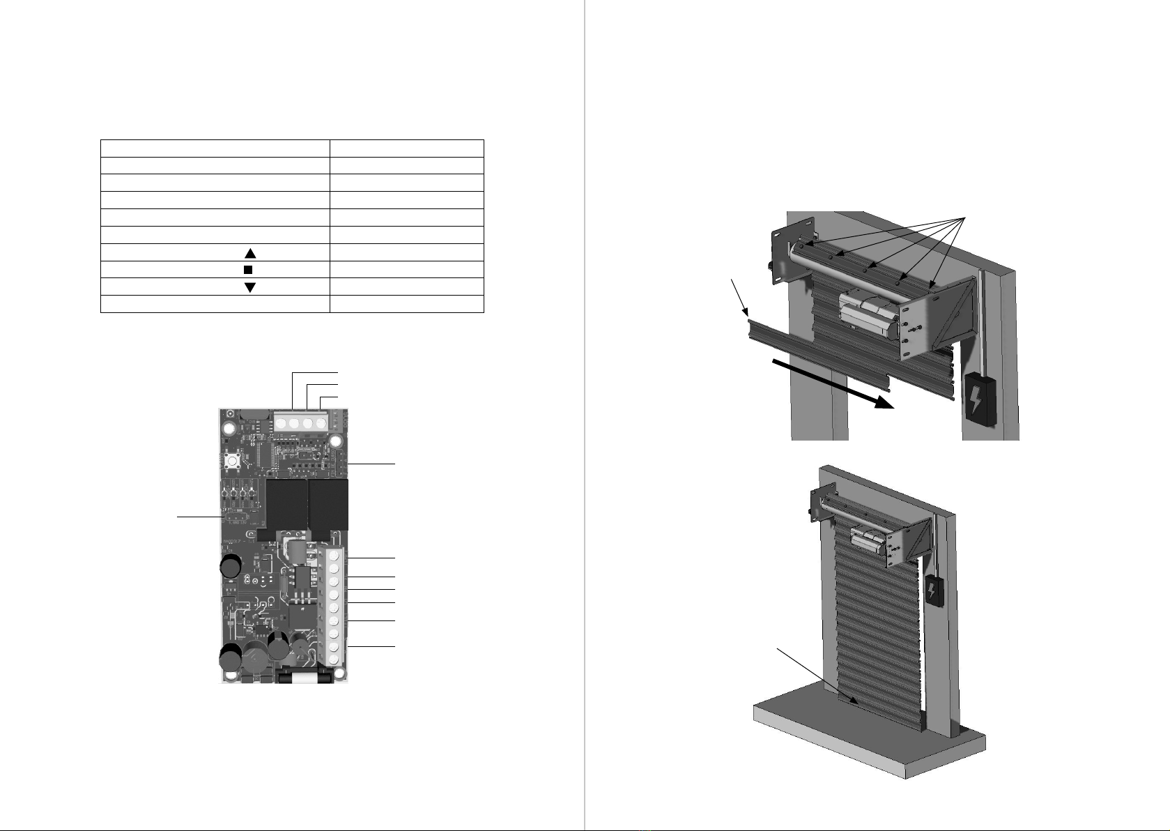
COMMAND BOARD:
Check the label attached to the product
(according to the model on the side)
which is the automation center. After
that, consult the control unit manual
that is available for download at
www.ppa.com.br and make all the
connections and congurations.
Batch:
Code:
Model:
Reduction:
Technology:
Voltage:
Board:
Size:
Mounting:
Housing:
Gear:
MAINTENANCE
In the table below, some PROBLEMS will be mentioned — DEFECTS, PROBABLE
CAUSES AND CORRECTIONS — that may occur in your Operator. Before any
maintenance, it is necessary to completely disconnect the electrical network.
DEFECTS PROBABLE CAUSES CORRECTIONS
Motor does not
start / does not
move
A) Power o
B) Fuse open / blown
C) Locked gate
D) Limit switch with defective
A) Make sure the mains is
connected correctly
B) Replace the fuse with the same
specication
C) Make sure there is no object
blocking the
gate operation
D) Replace the limit switch system
(analog and/or digital)
Motor blocked A) Inverted motor connection
B) Locked gate or operator
A) Check the motor wires
B) Put in manual mode and check
separately
Electronic board
does not accept
command
A) Fuse blown
B) Mains disconnected (power
supply)
C) Defect in the discharged remote
control
D) Transmitter range (remote
control)
A) Replace the fuse
B) Turn on the mains (power supply)
C) Check and change battery
D) Check the position of the
receiver antenna and, if necessary,
reposition it to ensure range
Motor only turns
to one side
A) Inverted motor wires
B) Inverted limit switch system
C) Defect in the command board
A) Check the motor connection
B) Invert the limit switch connector
(analog and/or digital)
C) Replace the command board
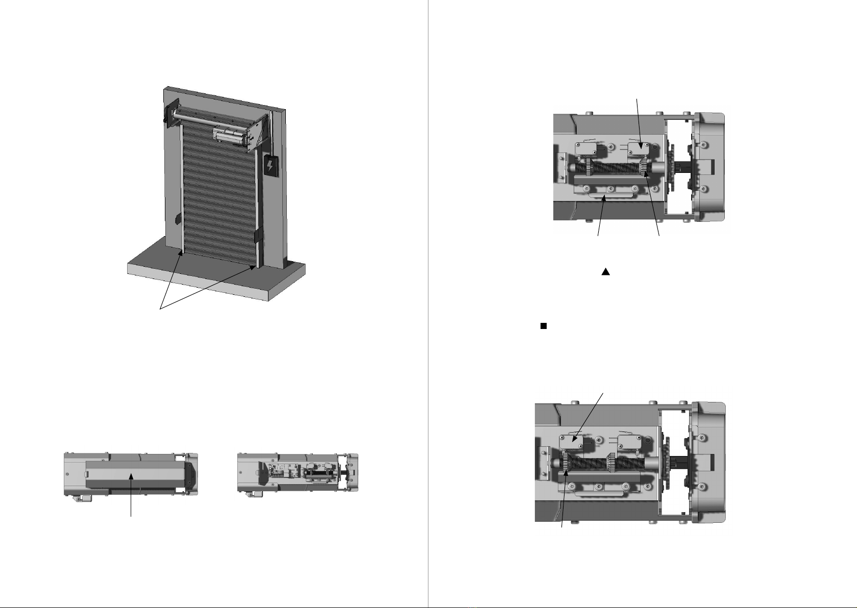
4th Step: With the two limit switches adjusted, do the opening and closing test.
Press the DOWN button ( ) to close the door, after it is completely closed, press
the UP button ( ) to open the door and wait for it to open completely. There is
also the STOP ( ), option, which works both to stop the door from opening and
to stop the door from closing.
SAFETY ITEMS
It is recommended to use a photocell (for doors up to 10 meters), as exemplied in
the image below:
It is also recommended to install the Anti-Fall Device, which prevents the door
leaf from falling in cases of poor structural installation or unnatural wear of door
components. This safety device must be installed on the opposite side of Operator
BR1. As shown in the image below: