PPI Zenex User manual

zenex
User Manual
Universal Self-Tune PID
Temperature Controller with
Programmable Timer

CONTENTS
User Manual
zenex
1. FRONT PANEL LAYOUT 1
2. BASIC OPERATION 3
3. SET UP MODE : ACCESS & OPERATION 7
4. I / O CONFIGURATION PARAMETERS 9
5. OP2 FUNCTION PARAMETERS 11
6. OP3 FUNCTION PARAMETERS 14
7. PID CONTROL PARAMETERS 16
8. SOAK TIMER PARAMETERS 18
9. SUPERVISORY PARAMETERS 21
10. HARDWARE ASSEMBLY AND CONFIGURATIONS 24
11. MECHANICAL INSTALLATION 30
12. ELECTRICAL CONNECTIONS 32
For Size 96X96
1. FRONT PANEL LAYOUT 36
2. 38HARDWARE ASSEMBLY AND CONFIGURATIONS
3. ELECTRICAL CONNECTIONS 41
For Size 48X48

1
FRONT PANEL LAYOUT
Figure 1.1
PPI
OP1 OP2 OP3
Upper Readout
Lower Readout
Output-3 Indicator
ENTER Key
UP Key
DOWN Key
PAGE Key
Output-1 Indicator
Output-2 Indicator
Soak Status
Indicator
Balance Soak
Time Indicator
S
T
zenex
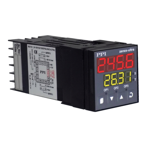
The front panel contains digital readouts, LED indicators and keys.
READOUTS
The Upper Readout is a 4 digit, 7-segment bright red LED display and usually displays the PV (Process Value). In Program
Mode, the Upper Readout displays parameter values/options.
The Lower Readout is a 4 digit, 7-segment bright green LED display and usually displays SP (Control Setpoint) Value. In
Program Mode, the Lower Readout displays parameter names (prompts).
INDICATORS
The Table 1.1 lists each front panel LED and the associated status.
Table 1.1
Status
Indicator
S
TGlows while the Lower Readout shows the Balance Soak Time in Main display
mode.
• Flashes while the Soak Timer is counting down.
• Glows steadily while the Soak Timer is outside the Timer Start Band or Hold
Band (that is, HOLD state).
• Indicates Output-1 ON/OFF status if the Control Output is Relay or SSR
drive.
• Remains OFF if the Control Output is DC Linear.
OP1
• Indicates Output-2 status if OP2 function is Auxiliary / Blower Control.
• Flashes Alarm-1 status if OP2 function is Alarm.
OP2
OP3 • Indicates Output-3 status if OP3 function is Auxiliary Control.
• Flashes Alarm-2 status if OP3 function is Alarm.
User Manual
zenex
Section 1

2
KEYS
The Table 1.2 lists the four front panel keys and the associated function.
Table 1.2
User Manual
zenex
Symbol Key Function
Press to enter or exit set-up mode.
DOWN
UP
ENTER Press to store the set parameter value and to scroll
to the next parameter on the PAGE.
Press to increase the parameter value. Pressing
once increases the value by one count; holding
pressed speeds up the change.
Press to decrease the parameter value. Pressing
once decreases the value by one count; keeping
pressed speeds up the change.
PAGE

3
BASIC OPERATIONS
POWER-UP
Upon power-up all displays and indicators are lit on for approximately 3 seconds. This is followed by the indication of the
controller model name on the Upper Readout and the firmware version on the Lower Readout, for
approximately 1 second.
MAIN DISPLAY MODE
After the Power-up display sequence, the Upper Readout starts showing the measured PV (Process Value) and the Lower
Readout displays the SP (Control Setpoint). This is the MAIN Display Mode that shall be used most often.
Adjusting SP (Control Setpoint)
The SP value can be directly adjusted on the Lower Readout while the controller is in the MAIN Display Mode.
If permitted at Supervisory Level, step through the following sequence for adjusting the SP value :
1. While the Lower Readout shows SP value, press and release UP or DOWN key once. The Lower Readout starts flashing.
2. Use UP/DOWN keys to adjust the SP value.
3. Press and release ENTER key. The Lower Readout stops flashing and the new set value is registered and stored.
Tune / Optimize Indication
The controller self detects the events such as new installation, significant change in SP, etc. for auto tuning itself to the process
under control. Also, the controller can be issued ‘Optimize’ command by the user for optimization of the PID constant values.
While the controller is Tuning/Optimizing, the Lower Readout flashes the message (Busy). The user is advised not to
disturb the process or alter any parameter values while the “Busy” message is being flashed. The “Busy” message
automatically disappears upon completion of Tuning/Optimization.
Timer (Soak) Mode Indication
While Soak Timer is in progress, the front panel indicator ‘S’ flashes if the timer is counting down or glows steadily if the timer is
in wait / hold state.
The Lower Readout can be toggled to display either Balance Soak Time or Control Setpoint (SP), using ENTER key. While the
Lower Readout shows balance soak time the indicator ‘T’ glows.
The Balance Soak time is in either ‘Minutes : Seconds’ or ‘Hours : Minutes’ or ‘Hours’, depending upon the time units selected
for the Soak Timer. If the selected time units are ‘Hours’, then (a) If the balance time is greater than 100 Hours, the time is
shown in ‘Hours’. (b) If the balance time is less than 100 Hours, the time is shown in ‘Hours : Minutes’.
PV Error Indications
The process value is said to be in error if it exceeds the minimum / maximum range specified for the selected Input sensor type
or if the sensor is disconnected (Open or Broken).
The PV Error type is indicated (flashing) on the Upper Readout. For different errors and the causes refer Table 2.1 below.
User Manual
zenex
Section 2

4
Table 2.1
Message PV Error Type
Open
Sensor / RTD broken
Under-range
PV below Min. Range
Over-range
PV above Max. Range
CONTROL/ALARM STATUS UNDER PV ERROR CONDITIONS
a) The tuning, if in progress, is aborted.
b) The Soak Timer, if in progress, enters in Pause (halt) state.
c) All the control outputs are switched off.
d) For Alarm activation, the under-range condition is treated as minimum PV, whereas the over-range and open conditions
are treated as maximum PV. Thus, Process High, positive Deviation Band and Window Band alarms activate under Over-
range/Open error. Similarly, Process Low, negative Deviation Band and Window Band alarms activate under Under-
range error.
OPERATOR PAGE AND PARAMETERS
The controller provides a separate page that contains parameters that require frequent settings by the operator. The page is
called Operator Page and the parameters are called Operator Parameters. The availability of operator parameters is
controlled at supervisory level and these parameters are not affected by the master lock status.
Accessing Operator Page & Adjusting Parameters
Step through the following sequence to open the operator page and to adjust the operator parameter values.
1. Press and release PAGE key. The Lower Readout shows (PAGE) and Upper Readout shows (0).
2. Press ENTER key. The Lower Readout shows prompt for the first available operator parameter and the Upper Readout
shows value for the parameter.
3. Use UP/DOWN keys to adjust the value and then press ENTER key to store the set value and scroll to next parameter.
The controller automatically reverts to MAIN Display Mode upon scrolling through the last operator parameter. Alternatively,
use PAGE key to return to MAIN Display Mode.
The Operator Parameters are described in Table 4. Note that the parameters presented on operator page depend upon the
functions selected / enabled.
The operator parameter list mainly includes :
a) Soak Start / Abort Command, if Soak Time feature is enabled.
b) The Control Setpoint (SP).
c) Alarm-1 Setpoint or Blower Setpoint or Auxiliary Control Setpoint for OP2 depending upon the function selected.
d) Alarm-2 Setpoint or Auxiliary Control Setpoint for OP3 depending upon the function selected.
e) Lock for Setpoint Editing on Lower Readout.
User Manual
zenex

5
User Manual
zenex
No
Yes
Parameter Description Settings
TIMER START COMMAND
Set to Yes to start Soak Timer. Not available if timer already
running.
TIMER ABORT COMMAND
Set to Yes to abort a running timer.
The set time value for the soak timer in the selected time units.
TIME DURATION 00.05 to 60.00 M:S
or
00.05 to 99.55 H:M
or
1 to 999 Hours
Parameter Description Settings
OP2 Function : Alarm-1
ALARM-1 SETPOINT
Process High / Process Low Alarm-1 Setpoint.
Min. to Max.
Range for the
Input Type
ALARM-1 DEVIATION BAND
Positive (+) or Negative (-) Alarm-1deviation band.
-1999 to 9999 or
-199.9 to 999.9
ALARM-1 WINDOW BAND
Symmetrical Alarm-1 window band.
3 to 999 or
0.3 to 99.9
OP2 Function : Auxiliary Control
Parameter Description Settings
Positive (+) or Negative (-) offset to Control Setpoint (SP) for
defining Auxiliary Setpoint.
AUXILIARY CONTROL SETPOINT
(Min. Range - SP)
to
(Max. Range - SP)
for selected Input
No
Yes
Table 2.2

6
User Manual
zenex
Parameter Description Settings
OP2 Function : Blower / Compressor Control
Positive (+) offset to Control Setpoint (SP) for defining Blower /
Compressor Setpoint.
BLOWER / COMPRESSOR SETPOINT
0 to 250 or
0.0 to 25.0
Parameter Description Settings
OP3 Function : Alarm-2
Process High / Process Low Alarm-2 Setpoint.
ALARM-2 SETPOINT Min. to Max.
Range for the
Input Type
Positive (+) or Negative (-) Alarm-2 deviation band.
ALARM-2 DEVIATION BAND -1999 to 9999 or
-199.9 to 999.9
Symmetrical Alarm-2 window band.
ALARM-2 WINDOW BAND 3 to 999 or
0.3 to 99.9
OP3 Function : Auxiliary Control
Parameter Description Settings
Positive (+) or Negative (-) offset to Control Setpoint (SP) for
defining Auxiliary Setpoint.
AUXILIARY CONTROL SETPOINT
(Min. Range - SP)
to
(Max. Range - SP)
for selected Input
Control Setpoint (SP) Locking
Parameter Description Settings
SETPOINT LOCKING
Set to Yes to lock the SP editing on the Lower Readout. No
Yes

7
The various parameters are arranged in different groups, called PAGES, depending upon the functions they represent. Each
group is assigned a unique numeric value, called PAGE NUMBER, for its access.
The parameters are always presented in a fixed format: The Lower Readout displays the parameter prompt (Identification
Name) and the Upper Readout displays the set value. The parameters appear in the same sequence as listed in their
respective sections.
SET-UP MODE
The Set-up Mode allows the user to view and modify the parameter values. Follow the steps below for setting the parameter
values:
1. Press and release PAGE key. The Lower Readout shows PAGE and the Upper Readout shows page number 0. Refer
Figure 3.1.
2. Use UP / DOWN keys to set the desired PAGE NUMBER.
3. Press and release ENTER key. The Lower Readout shows the prompt for the first parameter listed in the set PAGE and
the Upper Readout shows its current value. (If the entered PAGE NUMBER is invalid (contains no parameter list or any
associated function), the controller reverts to the MAIN Display Mode.
4. Press and release the ENTER key until the prompt for the required parameter appears on the Lower Readout. (The last
parameter in the list rolls back to the first parameter).
5. Use UP / DOWN keys to adjust the parameter value. (The display flashes if UP key is pressed after reaching the maximum
value or DOWN key is pressed after reaching the minimum value).
6. Press and release the ENTER key. The new value gets stored in the controller’s non-volatile memory and the next
parameter in the list is displayed.
The Figure 3.1 illustrates the example of altering the value for the parameter ‘Input Type’.
SET-UP MODE : ACCESS AND OPERATION
Figure 3.1
Notes
1. Each page contains a fixed list of parameters that are presented in a pre-determined sequence. Note however that
availability of a few parameters, called Conditional Parameters, depend upon the settings for some other parameters. For
example, the parameter ‘Control Hysteresis’ for Output-1 is available only if, the set value for the parameter ‘Control
Action’ is ‘On-Off’.
2. To exit the set-up mode and return to the MAIN Display Mode, press and release PAGE key.
3. If no key is pressed for approximately 30 seconds, the set-up mode times out and reverts to the MAIN Display Mode.
User Manual
zenex
or
Main Display
Mode
Default Page Page Number
Press PAGE
key to enter
Set-up Mode
Use UP/DOWN
key to set the
Page Number
Press ENTER
key to open
the Page
Use UP/DOWN
keys to change
the value
Press ENTER
key to store the value &
move to next parameter
First Parameter
on Page-10
New Parameter
value
Next Parameter
on Page-10
or
Section 3

8
MASTER LOCKING
The controller facilitates locking all the PAGES (except Operator PAGE) by applying Master Lock Code. Under Locking, the
parameters are available for view only and cannot be adjusted. The Master Lock, however does not lock the operator
parameters. This feature allows protecting the rather less frequently used parameters against any inadvertent changes while
making the frequently used operator parameters still available for any editing.
For enabling / disabling the Lock, step through the following sequence:
Locking
1. Press and release PAGE key while the controller is in the MAIN Display Mode. The Lower Readout shows PAGE and the
Upper Readout shows 0.
2. Use UP / DOWN keys to set the Page Number to 123 on the Upper Readout.
3. Press and release ENTER key. The controller returns to the MAIN Display Mode with the Lock enabled.
The Figure 3.2 below illustrates the Locking procedure.
UnLocking
Repeat the Locking procedure twice for unlocking.
User Manual
zenex
Figure 3.2
or
MAIN Display
Mode
Default Page Locking Code MAIN Display
Mode
Press PAGE
key to enter
Set-up Mode
Use UP/DOWN
key to set the
‘Locking Code’
Press ENTER key
to Lock & Return to
Main Mode

9
Table 4.1
Parameter Description Settings
Default Value
INPUT TYPE Refer Table 4.2
(Default : Type K)
Refer Table 4.2 for various available ‘Input Types’ along with their
respective Ranges and Resolutions.
TEMPERATURE DISPLAY UNITS
Select as ‘°C’ (Centigrade) or ‘°F’ (Fahrenheit).
°C
°F
(Default : °C)
TEMPERATURE RANGE
This parameter value must be set in accordance with the
Maximum Temperature Range for which the equipment / machine
is designed. Set this parameter value appropriately as the same is
used by the controller to determine whether or not to Self-Tune /
Optimize the controller upon detecting the “Tune at Setpoint
Change” condition.
CONTROL OUTPUT TYPE
Refer Table 4.3 for the available options.
Refer Table 4.3
(Default : Relay)
CONTROL MODE
On-Off
The control algorithm tends to maintain the PV at SP by either
switching the output (say, Heater) fully OFF or fully ON. The On
and Off switching is differentiated by the user settable ‘Hysteresis
Band’.
PID
The control algorithm uses a 2nd order equation to compute the
‘% Output Power’ required to maintain the PV at SP. The constants
P, I, D are automatically set by the controller.
On-Off
PID
(Default : PID)
CONTROL LOGIC
Direct
Cooling Control (Output Power increases with increase in PV).
Reverse
Heating Control (Output Power decreases with increase in PV).
Direct
Reverse
(Default : Reverse)
HYSTERESIS
(For ON-OFF Control only)
Sets a differential (dead) band between the ON and OFF states.
Keep it large enough to avoid frequent switching of the load
without losing the desired control accuracy.
1 to 999°C or
0.1 to 99.9°C
(Default : 2 or 0.2)
User Manual
zenex
I / O CONFIGURATION PARAMETERS
Section 4
(Default : 1375)
Min. to Max. specified
for the selected Input Type
(Refer Table 4.2)

10
Parameter Description Settings
Default Value
SETPOINT LOW LIMIT
This parameter sets the minimum limit on the Control Setpoint
value. (Default : -200)
This parameter sets the maximum limit on the Control Setpoint
value.
SETPOINT HIGH LIMIT
Setpoint Low to
Max. Range for the
selected Input Type
(Default : 1375)
Table 4.2
Table 4.3
Option What it means Remarks
Applicable for OP1 as
Relay / SSR
0 to 20 mA current
4 to 20 mA current
0 to 5 Volts
0 to 10 Volts
Applicable for OP1 as
DC Linear Voltage
Applicable for OP1 as
DC Linear Current
Relay
SSR (Solid State Relay)
User Manual
zenex
Min. Range to
Setpoint High for the
selected Input Type
Option What it means Range
(Min. to Max.)
Type J Thermocouple
Type K Thermocouple
Type T Thermocouple
0 to +960°C / +32 to +1760°F
-200 to +1375°C / -328 to +2508°F
-200 to +385°C / -328 to +725°F
Type R Thermocouple
Type S Thermocouple
Type B Thermocouple
Type N Thermocouple
0 to +1770°C / +32 to +3218°F
0 to +1765°C / +32 to +3209°F
0 to +1825°C / +32 to +3092°F
0 to +1300°C / +32 to +2372°F
Fixed
1°C / 1°F
3-wire, RTD Pt100
-199 to +600°C / -328 to +1112°F
-199.9 to 600.0°C / -199.9 to 999.9°F
0.1°C / 0.1°F
3-wire, RTD Pt100
Resolution
(Fixed or settable)

11
None
Alarm
Control
Blower
(Default : None)
Parameter Description Settings
Default Value
Table 5.1
OUTPUT-2 FUNCTION SELECTION
None
OP2 module not installed or function not used.
Alarm
OP2 relay activates as Alarm status.
Auxiliary Control
OP2 relay activates as Auxiliary control status.
Blower
OP2 relay activates as Blower / Compressor control status.
OP2 Function : Alarm-1
Parameter Description Settings
Default Value
TYPE
Process Low
The alarm activates for PV less than or equal to Alarm Setpoint.
Process High
The alarm activates for PV greater than or equal to Alarm Setpoint.
Deviation Band
The alarm activates if the PV deviation from SP is greater than the
set positive or negative ‘Deviation Band’ value.
Window Band
The alarm activates if the PV deviation from SP is greater than the
set ‘Window Band’ value in either direction.
End Of Soak
The OP2 Relay / SSR is switched ON for the time duration set for
the parameter ‘Alarm Timer’.
SETPOINT
Available for ‘Process High’ or ‘Process Low’ Alarms. Sets the
Upper (Process High) or Lower (Process Low) Alarm Limit.
Min. to Max. Range for
the selected Input type
(Default : 0)
DEVIATION BAND
Available for ‘Deviation Band’ Alarm. Sets a deviation band above
(Positive value) or below (Negative value) the SP for alarm
activation.
-1999 to 9999 or
-199.9 to 999.9
(Default : 0)
WINDOW BAND
Available for ‘Window Band’ Alarm. Sets a symmetrical band
above and below the SP for alarm activation.
3 to 999 or 0.3 to 99.9
(Default : 3)
User Manual
zenex
OP2 FUNCTION PARAMETERS
Section 5
Process Low
Process High
Deviation Band
Window Band
End of Soak
(Default : Process Low)

12
Yes
No
(Default : Yes)
Normal
Reverse
(Default : Normal)
Parameter Description Settings
Default Value
LOGIC
Normal
The Alarm output (Relay/SSR) remains ON under alarm condition;
OFF otherwise. Useful for Audio / Visual Alarm.
Reverse
The Alarm output (Relay / SSR) remains OFF under alarm
condition; ON otherwise. Useful for Tripping the system under
control.
INHIBIT
No
Alarm is not suppressed for start-up condition.
Yes
The Alarm activation is inhibited (suppressed) until the PV is found
within alarm limits from the time the controller is switched ON.
ALARM TIMER
Available for End of Soak Alarm. Sets time duration in seconds for
which the alarm shall activate upon end of soak timer.
5 to 250 Seconds
(Default : 10)
OP2 Function : Auxiliary Control
User Manual
zenex
Parameter Description Settings
Default Value
OFFSET VALUE
Offset value for the Auxiliary Control Setpoint. Can be set as
positive value or negative value.
Auxiliary Control Setpoint = Control Setpoint (SP) + Offset Value
(Min. Range - SP) to
(Max. Range - SP) specified
for the selected Input Type
(Default : 0)
HYSTERESIS
Sets a differential (dead) band between the ON and OFF control
states.
1 to 999 or
0.1 to 99.9
(Default : 2 or 0.2)
CONTROL LOGIC
Normal
The Output remains ON for PV below Setpoint and OFF
otherwise.
Reverse
The Output remains ON for PV above Setpoint and OFF
otherwise.
Normal
Reverse
(Default : Normal)

13
OP2 Function : Blower / Compressor Control
Parameter Description Settings
Default Value
OFFSET VALUE
Sets a positive (+) offset to the SP to define the ‘Blower /
Compressor Setpoint’.
Blower / Compressor Setpoint = Control Setpoint (SP) + Offset
Value
0 to 250 or
0.0 to 25.0
(Default : 0)
HYSTERESIS
Differential (dead) band between the blower ON and OFF states.
1 to 250 or
0.1 to 25.0
(Default : 2 or 0.2)
TIME DELAY
This parameter is mainly used for Compressor Load. The set time
delay is elapsed each time before the compressor is switched ON.
Set the value to 0 if no Time Delay is required.
00.00 to 10.00 Min. Sec
(in steps of 5 Seconds)
(Default : 00.00)
User Manual
zenex

14
None
Alarm
Control
(Default : None)
Parameter Description Settings
Default Value
OUTPUT-3 FUNCTION SELECTION
None
OP2 module not installed or function not used.
Alarm
OP2 relay activates as Alarm status.
Auxiliary Control
OP2 relay activates as Auxiliary control status.
OP3 Function : Alarm-2
Table 6.1
User Manual
zenex
OP3 FUNCTION PARAMETERS
Parameter Description Settings
Default Value
TYPE
Process Low
The alarm activates for PV less than or equal to Alarm Setpoint.
Process High
The alarm activates for PV greater than or equal to Alarm Setpoint.
Deviation Band
The alarm activates if the PV deviation from SP is greater than the
set positive or negative ‘Deviation Band’ value.
Window Band
The alarm activates if the PV deviation from SP is greater than the
set ‘Window Band’ value in either direction.
End Of Soak
The OP2 Relay / SSR is switched ON for the time duration set for
the parameter ‘Alarm Timer’.
SETPOINT
Available for ‘Process High’ or ‘Process Low’ Alarms. Sets the
Upper (Process High) or Lower (Process Low) Alarm Limit.
Min. to Max. Range for
the selected Input type
(Default : 0)
DEVIATION BAND
Available for ‘Deviation Band’ Alarm. Sets a deviation band above
(Positive value) or below (Negative value) the SP for alarm
activation.
-1999 to 9999 or
-199.9 to 999.9
(Default : 0)
WINDOW BAND
Available for ‘Window Band’ Alarm. Sets a symmetrical band
above and below the SP for alarm activation.
3 to 999 or 0.3 to 99.9
(Default : 3)
Section 6
(Default : Process Low)
Process High
Deviation Band
Window Band
End of Soak
Process Low

15
User Manual
zenex
OP3 Function : Auxiliary Control
Parameter Description Settings
Default Value
(Min. Range - SP) to
(Max. Range - SP) specified
for the selected Input Type
(Default : 0)
1 to 999 or
0.1 to 99.9
(Default : 2 or 0.2)
Normal
Reverse
(Default : Normal)
OFFSET VALUE
Offset value for the Auxiliary Control Setpoint. Can be set as
positive value or negative value.
Auxiliary Control Setpoint = Control Setpoint (SP) + Offset Value
HYSTERESIS
Sets a differential (dead) band between the ON and OFF control
states.
CONTROL LOGIC
Normal
The Output remains ON for PV below Setpoint and OFF otherwise.
Reverse
The Output remains ON for PV above Setpoint and OFF otherwise.
Parameter Description Settings
Default Value
LOGIC
Normal
The Alarm output (Relay/SSR) remains ON under alarm condition;
OFF otherwise. Useful for Audio / Visual Alarm.
Reverse
The Alarm output (Relay / SSR) remains OFF under alarm
condition; ON otherwise. Useful for Tripping the system under
control.
5 to 250 Seconds
(Default : 10)
INHIBIT
No
Alarm is not suppressed for start-up condition.
Yes
The Alarm activation is inhibited (suppressed) until the PV is found
within alarm limits from the time the controller is switched ON.
ALARM TIMER
Available for End of Soak Alarm. Sets time duration in seconds for
which the alarm shall activate upon end of soak timer.
Normal
Reverse
(Default : Normal)
Yes
No
(Default : Yes)

16
Table 7.1
Parameter Description Settings
Default Value
Not Applicable
(Default : Not Applicable)
0.5 to 120.0 Seconds
(in steps of 0.5 secs.)
(Default : 0.5)
(Default : 10.0)
0.1 to 999.9
% OUTPUT POWER
This is a view only parameter that facilitates the indication of ‘%
Output Power’ computed by the controller PID algorithm. The
computed value lies between Min. power (0.0%) and Max. power
(100.0%).
CYCLE TIME
(For ‘PID’ Control)
For time-proportionating PID control, the output power is
implemented by adjusting the ratio of ON : OFF to a fixed time
interval, called ‘Cycle Time’. The larger the power the larger the
ON time and vice-a-versa.
Larger Cycle time ensures longer Relay/SSR life but may result in
poor control accuracy and vice-a-versa.The recommended Cycle
Time values are; 20 sec. for Relay and 1 sec. for SSR.
PROPORTIONAL BAND
(For ‘PID’ Control)
The Proportional band is defined in terms of process value
deviation from the setpoint (also known as process error). Within
the band the output power is varied from maximum (100%) at
maximum deviation to minimum (0%) at minimum deviation. The
process value thus tends to stabilize at a point within the band
where the power input equal losses. Larger Band results in better
stability but larger deviation.
The Proportional Band value is automatically calculated by
controller’s Self-Tune feature and seldom requires any manual
adjustment.
INTEGRAL TIME
(For ‘PID’ Control)
The application of proportional band alone results in process
value stability within the band but away from the setpoint. This is
called steady state Offset Error. The integral action is incorporated
for automatic removal of offset error with minimum ocillations.
The Integral Time value is automatically calculated by controller’s
Self-Tune feature and seldom requires any manual adjustments.
0 to 1000 Seconds
(Default : 100)
User Manual
zenex
PID CONTROL PARAMETERS
Section 7

17
Parameter Description Settings
Default Value
DERIVATIVE TIME
(For ‘PID’ Control)
It is desired that the controller should respond to any dynamic
changes in the process conditions (like variations in load, power
supply fluctuations, etc.) fast enough so as retain the process
value near the setpoint. The derivative time determines how
strong the output power will change in response to the rate of
change of measured PV.
The Derivative Time value is automatically calculated by
controller’s Self-Tune feature and seldom requires any manual
adjustments.
0 to 250 Seconds
(Default : 25)
User Manual
zenex

18
(Refer end of this section for detailed Soak Timer Operation)
User Manual
zenex
SOAK TIMER PARAMETERS
Table 8.1
Min:Sec
Hours:Min
Hours
(Default : Min: Sec)
Parameter Description Settings
Default Value
TIMER ENABLE
Yes
No
(Default : No)
Yes
Soak Timer function and Start / Abort commands are enabled.
No
Soak Timer function and Start / Abort commands are disabled.
TIME UNITS
Select the time units depending on the minimum and/or maximum
time value required.
TIME DURATION
The preset time value in selected units for the Soak Timer.
00.05 to 60:00 Min:Sec
00.05 to 99:55 Hrs:Min
1 to 999 Hours
(Default : 00.10 Min:Sec)
TIMER-START BAND
After issuance of start command, the timer starts counting down
once the PV enters the process band around SP defined by this
parameter value.
0 to 9999 or
0.0 to 999.9
(Default : 5 or 0.5)
HOLDBACK STRATEGY
None
Up
Down
Both
(Default : None)
None
PV based timer pause is not required.
Up
Timer is paused if PV is outside holdband above SP.
Down
Timer is paused if PV is outside holdband below SP.
Both
Timer is paused if PV is outside holdband both above and below
SP.
HOLD BAND
Sets the temperature limit(s) with respect to the SP for the timer to
pause. The timer holds on counting should the PV cross the
limit(s).
1 to 9999 or
0.1 to 999.9
(Default : 5 or 0.5)
SWITCH-OFF CONTROL
OUTPUT AT TIMER END
Yes
The control output (OP1) is forced off upon completion of timer.
No
The control output state is not forced.
Yes
No
(Default : No)
Section 8
Table of contents
Other PPI Temperature Controllers manuals
Popular Temperature Controllers manuals by other brands
Extech Instruments
Extech Instruments RHT50 user guide
Glas-Col
Glas-Col LimiTrol 104A PC512 User instructions
Tech Controllers
Tech Controllers EU-281 user manual
Shimaden
Shimaden SR70 Series instruction manual
Sentera
Sentera RXTP Series Mounting and operating instructions
Liebert
Liebert Liebert iCOM user manual
