manuals.online logo
Brands
  1. Home
  2. •
  3. Brands
  4. •
  5. Dimplex
  6. •
  7. Temperature Controllers
  8. •
  9. Dimplex RTW 401 UN User manual

Dimplex RTW 401 UN User manual

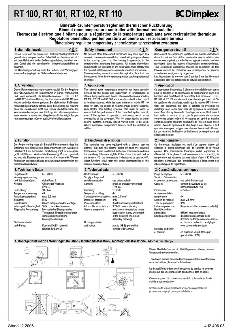
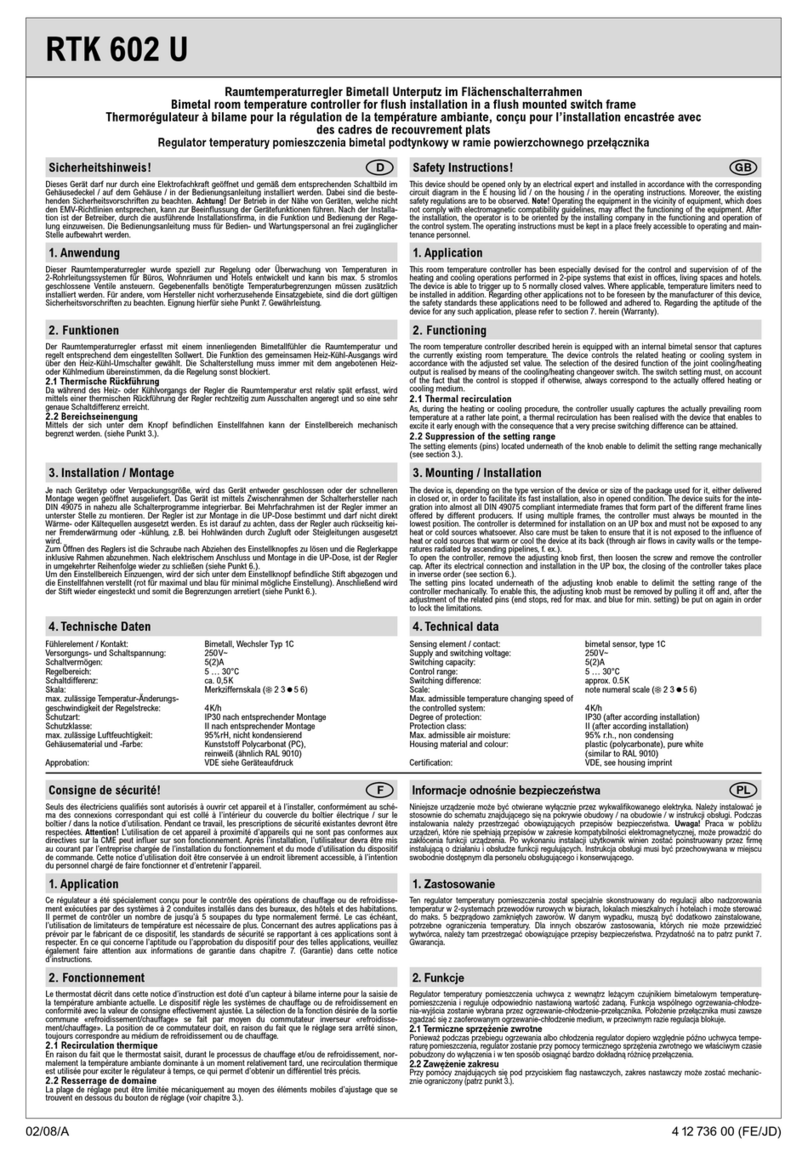
RTW 401 UN
02/08/A 1 5 21404 00 (FE)
Raumtemperaturregler im Flächenschalterrahmen für Unterputzmontage mit Bodentemperaturwächter
Room temperature controller for installation in a flush mounted switch frame with floor temperature thermostat
Thermorégulateur avec contrôleur de température du plancher pour la régulation de la température ambiante; installation encastrée dans un
cadre de recouvrement plat
Regulator temperatury pomieszczenia, do podtynkowego montażu w ramie powierzchownego przełącznika z czujnikiem temperatury podłogi
Sicherheitshinweis!
Dieses Gerät darf nur durch eine Elektrofachkraft geöffnet und gemäß dem entsprechenden Schaltbild im
Gehäusedeckel / auf dem Gehäuse / in der Bedienungsanleitung installiert werden. Dabei sind die beste-
henden Sicherheitsvorschriften zu beachten. Achtung! Der Betrieb in der Nähe von Geräten, welche nicht
den EMV-Richtlinien entsprechen, kann zur Beeinflussung der Gerätefunktionen führen. Nach der Installa-
tion ist der Betreiber, durch die ausführende Installationsfirma, in die Funktion und Bedienung der Rege-
lung einzuweisen. Die Bedienungsanleitung muss für Bedien- und Wartungspersonal an frei zugänglicher
Stelle aufbewahrt werden.
1. Anwendung
In der Haustechnik zur fußbodenüberwachten Raumtemperaturregelung elektrischer Fußbodenheizungen
und Bodentemperiersysteme, in der UP-Dose montiert. Ist als eigenständiges Gerät einsetzbar oder
mittels Zwischenrahmen gemäß DIN 49075 in nahezu alle Flächenschaltersysteme adaptierbar.
Für andere, vom Hersteller nicht vorherzusehende Einsatzgebiete sind die dort gültigen Sicherheitsvor-
schriften zu beachten. Eignung hierfür siehe Punkt 17. Gewährleistung.
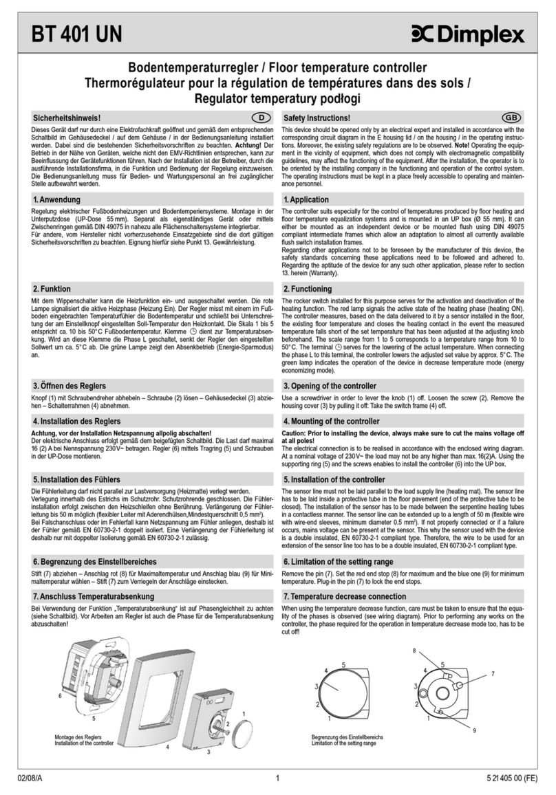
Safety Instructions!
This device should be opened only by an electrical expert and installed in accordance with the corresponding
circuit diagram in the E housing lid / on the housing / in the operating instructions. Moreover, the existing
safety regulations are to be observed. Note! Operating the equipment in the vicinity of equipment, which does
not comply with electromagnetic compatibility guidelines, may affect the functioning of the equipment. After
the installation, the operator is to be oriented by the installing company in the functioning and operation of the
control system. The operating instructions must be kept in a place freely accessible to operating and main-
tenance personnel.
1. Application
The controller suits especially for applications within the domestic engineering sphere. It has been devised
for the floor-temperature dependent control of room temperatures produced by electric floor heating or
temperature equalization systems and is mounted in an UP box (Ø 55 mm). It can either be mounted as
an independent device or be mounted flush using DIN 49075 compliant intermediate frames which
allow an adaptation to almost all currently available flush switch installation frames. Regarding
other applications not to be foreseen by the manufacturer of this device, the safety standards concerning
these applications need to be followed and adhered to. Regarding the aptitude of the device for any such
other application, please refer to section 17. herein (Warranty).
2. Funktion
Der Regler misst mit einem internen Fühler die Raumtemperatur und überwacht mit einem externen
Fühler die Bodentemperatur. Solange die maximale Bodentemperatur nicht überschritten wird, ist bei
Unterschreitung des Raumtemperatursollwertes der Heizkontakt geschlossen. Skala … 6 entspricht
ca. 5 … 30°C Raumtemperatur. Die rote Lampe signalisiert die aktive Heizphase. Mit dem Schalter kann
die Heizfunktion abgeschaltet werden.
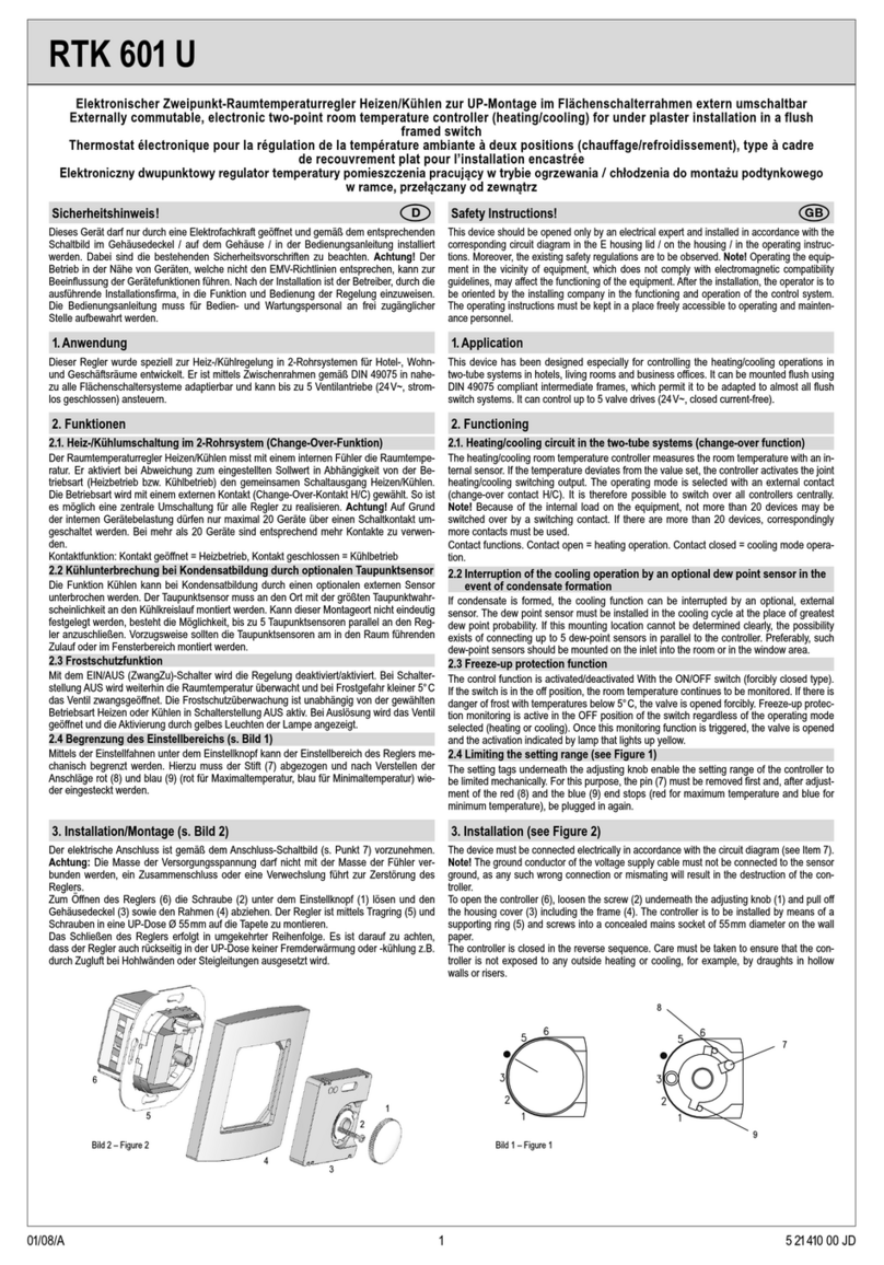
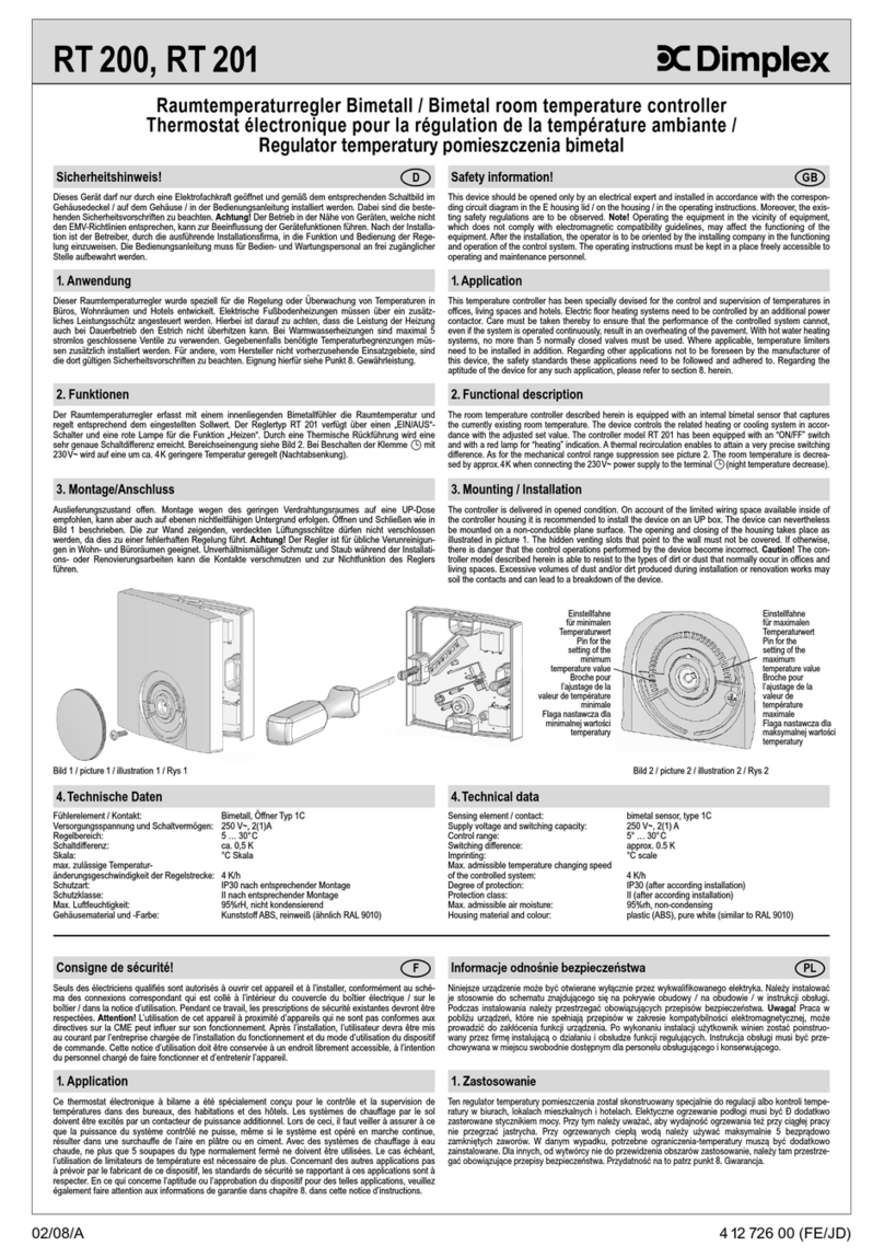
2. Functioning
The controller measures based on the data delivered to it by an internal sensor the existing room tempera-
ture and uses the data detected by an external sensor for the monitoring of the floor temperature. As long
as the maximum admissible floor temperature is not transcended, the heating contact is closed in the
event the actually measured temperature falls short of the previously adjusted room set temperature. The
scale range from to 6 corresponds to a temperature range from 5 to 30°C. The red lamp signals the
active state of the heating phase. The heating function can be deactivated by means of the switch.
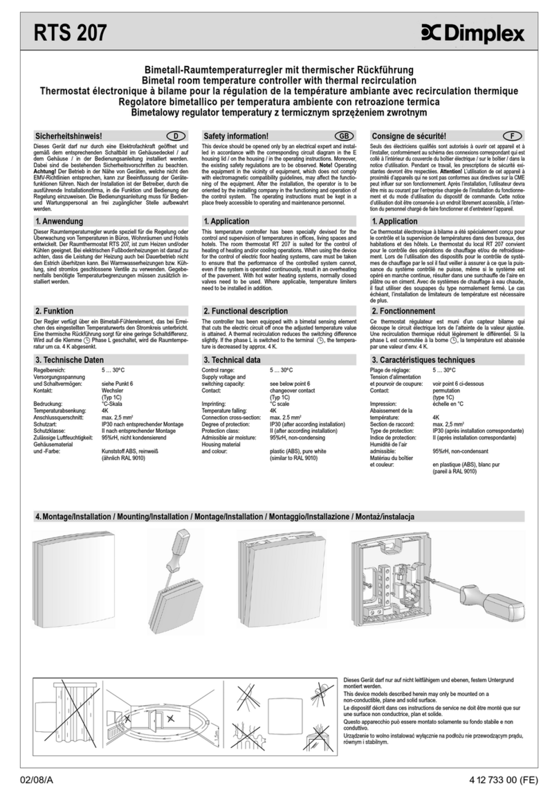
3. Öffnen des Reglers
Knopf (1) mit Schraubendreher abhebeln – Schraube (2) lösen – Gehäusedeckel (3) abziehen – Schalter-
rahmen (4) abnehmen.
3. Opening of the controller
Use a screwdriver in order to lever the knob (1) off. Loosen the screw (2). Remove the housing cover (3)
by pulling it off: Take the switch frame (4) off.
4. Installation des Reglers
Elektrischer Anschluss gemäß „Anschluss-Schaltbild“ (Bild 1) mit Schraubklemmen – Massivleiter Quer-
schnitt lastabhängig 1,5 … 2,5 mm2, Fühlerleitungsquerschnitt 0,5 mm2– kein Schutzleiter – Regler (6)
mittels Tragring (5) und Schrauben in UP-Dose auf Tapete montieren.
Nach der Installation muss der Regler mittels Poti (Bild 2) an die angeschlossene Last angepasst werden
(vgl. Punkt 14. „Lasteinstellung“).
4. Installation of the controller
The electrical connection is to be realised in accordance with the enclosed wiring diagram (picture 1) by
means of terminal screws. The cross-section of the solid conductor to be used depends on the actual load
and ranges thus from 1.5 to 2.5 mm2. The cross-section of the sensor line is 0.5 mm2. No protective earthing
wire is used. Using the supporting ring (5) and the screws enables to install the controller (6) into the UP
box. After completion of the installation works, the potentiometer provided for this purpose (picture 2) must
be used in order to adjust the controller to the actually connected load (see section 14., “Load adjustment”).
5. Installation des Überwachungsfühlers
Innerhalb der Wand und des Estrichs im Schutzrohr; – zwischen die Heizschleifen ohne Berührung; –
Parallelverlegung mit Netzkabel unzulässig; – Verlängerung bis 50 m mit 0,5 mm2(flexible Leiter mit
Aderendhülsen); bei Falschanschluss oder im Fehlerfall kann Netzspannung am Fühler anliegen,
deshalb ist doppelte Isolierung gemäß EN 60730-2-1 vorgeschrieben!
5. Installation of the temperature monitoring sensor
The sensor line has to be laid inside a protective tube within the wall or in the floor pavement. The installa-
tion of the sensor has to be made between the serpentine heating tubes in a contactless manner. The
parallel laying with power cables is inadmissible. The sensor line can be extended up to a length of 50 m
(flexible wires with wire-end sleeves, minimum diameter 0.5 mm2). Caution: If not properly connected or
if a failure occurs, mains voltage can be present at the sensor! This is why the sensor and the wire re-
quired for the extension of the sensor line must both be double insulated, EN 60730-2-1 compliant types!
6. Gerät schließen 6. Connection of the device
For the closing of the controller, follow the steps explained in above section 3. in inverse order.
8. Funktion Nachtabsenkung
Wird an die Anschlussklemme L angeschlossen, ist die Nachtabsenkung aktiv. Dies kann z.B. über
eine externe Schaltuhr oder einen Uhrenregler realisiert werden. Die grüne Lampe zeigt die aktive Nacht-
absenkung an. (Achtung! Zweite Einspeisung) – bei Arbeiten am Regler ist auch die Nachtabsen-
kung abzuschalten!
DGB
1
2
3
4
5
6
1
2
3
4
5
6
7
8
9
7
8
9
8. Night temperature decrease function
Once L is connected to the terminal , the night temperature decrease function is rendered active. This
can, for example, be realised by an external switch clock or a clock controller. The green lamp indicates
the active state of the night temperature decrease function (Caution: second incoming supply!). Prior to
performing any works on the controller, the night temperature decrease function too must be cut off!
9.Technische Daten
Betriebsspannung: 230V / 50Hz
Regelbereich: 5 … 30°C (Skala … 6)
Bodentemp.begrenzung 20 … 60°C (Skala 2 … 6) (intern einstellbar)
Schaltdifferenz: ca.1K
Leistungsaufnahme: ca.1W
Nachtabsenkung: ca. 4K fest; Anschluss an L
Kontakt: Schließer max. 230V 10 (1,5)A
Interner Fühler: 47k⏲, NTC
Externer Fühler (doppelt isoliert):
2k⏲, NTC entspr. DIN EN 44574-3, DIN EN 50350 entspr. DIN EN 60730-2-1
Fühlerbrucherkennung: Heizung wird abgeschaltet
Anzeigen: LED für Heizen, Nachtabsenkung
Schraubanschlüsse: 0,5 … 2,5mm2
Befestigung: in UP-Dose Ø 55 mm
Schutzart: IP30
Schutzklasse: II nach entspr. Montage
Umgebungstemperatur: 0 … 40°C
Lagertemperatur: 20 … +70°C
Funkentstörung: gemäß EN 50081-1, EN 50082-1
Operating voltage: 230V / 50Hz
Control range: 5 … 30°C (scale range … 6)
Floor temperature limitation: 20 … 60°C (scale range 2 … 6) (internally adjustable)
Switching difference: approx.1K
Power consumption: approx.1W
Night temperature decrease: approx. 4K (fixed); connection of to L
Contact: make contact, max. 230V 10(1.5)A
Internal sensor: 47k⏲, NTC
External sensor (double-insulated): 2k⏲, NTC acc. to. DIN EN 44574-3,
DIN EN 50350 in compliance with DIN EN 60730-2
Sensor breakdown detection: heating is turned off
Indicators: LED’s for heating and night temp. decrease mode
Terminal screws: screw terminals (0.5 … 2.5 mm2)
Mounting: in an UP box (Ø 55 mm)
Degree of protection: IP30
Protection class: II (after according installation)
Ambient temperature: 0 … 40°C
Storage temperature: -20 … +70°C
Radio interference suppression: acc. to EN 50081-1 and EN 50082-1
9.Technical Data
Das Schließen des Gerätes erfolgt in umgekehrter Reihenfolge zum Öffnen.
7. Begrenzung des Einstellbereiches
Stift (7) abziehen; – Anschlag rot (8) für Maximalteperatur und Anschlag blau (9) für Minimaltemperatur
verdrehen; – Stift (7) zum Verriegeln der Anschläge wieder einstecken.
7. Limitation of the setting range
Remove the pin (7). Set the red end stop (8) for maximum and the blue one (9) for minimum temperature.
Plug-in the pin (7) to lock the end stops.
Bedien- und Anzeigesymbole Anschluss-Symbole
Regelung EIN Anschluss Heizung
Regelung AUS Anschluss Nachtabsenkung
Heizung EIN L Anschluss Phase 230V~
Nachtabsenkung EIN N Anschluss Neutralleiter
Frostschutz (bei Regelung EIN) F Anschluss Fühler
Wohlfühltemperatur (ca. 20°C)
13. Verwendete Symbole
2
11. Anschluss-Schaltbilder und Maßzeichnungen / Wiring diagrams and dimensioned drawings
Operating and display symbols Connection symbols
Control ON Heating connection
Control OFF Night tem. decrease connection
Heating ON L Mains supply connection (phase) 230V~
Night temperature decrease ON N Neutral conductor connection
Frost protection (with control ON) F Sensor connection
Thermal well-being level (approx. 20°C)
13. Explanation of symbols
Temp. [ºC] R[k⏲] U [V]
10 3,66 2,59
20 2,43 2,34
25 2,00 2,20
30 1,65 2,06
40 1,15 1,77
50 0,82 1,48
60 0,59 1,22
12. Kennwerte des Fußbodentemperaturfühlers (NTC)
Temp. [ºC] R[k⏲] U [V]
10 3.66 2.59
20 2.43 2.34
25 2.00 2.20
30 1.65 2.06
40 1.15 1.77
50 0.82 1.48
60 0.59 1.22
12. Characteristics of the floor temperature sensor
Maßzeichnung Regler / Controller, dimensioned drawing Maßzeichnung Fühler / Sensor, dimensioned drawing
Elektronik
Electronics
Bild 1: Anschluss-Schaltbild /
Picture 1: wiring diagram
Fühler doppelt isoliert /
Double-insulated sensor
Last
max.10A
230V~
Load
max.10A
230V~
10. Zubehör
Der Regler wird komplett mit 4 m Hülsenfühler ausgeliefert.
10.Accessories
The controller is supplied complete with a corresponding sleeve sensor (4 m).
230V/50Hz
10
Last-Justage
Load adjustment
Fußbodentemperaturbegrenzung
Floor temperature limitation
Bild 2: Last- und Begrenzungseinstellung für Fußbodentemperatur
Picture 2: Load and limitation adjustment for floor temperature control
14. Lasteinstellung
Der Regler verfügt über einen internen Sensor, nach dem die Raumtemperatur geregelt wird. Die vom
Regler geschaltete Last verursacht eine interne Erwärmung, welche den Sensor beeinflusst. Um diese
Beeinflussung zu kompensieren, muß eine Lasteinstellung vorgenommen werden. Der Regler ist für eine
Last von 6A bis 7A (1350W bis 1600W) werkseitig eingestellt.
Durchführung der Lasteinstellung:
Das fertig montierte geschlossene Gerät einschalten. Den Temperatureinstellknopf für die entsprechende
Last gemäß der Lasteinstelltabelle einstellen. Drehknopf abnehmen und den Gehäusedeckel abschrau-
ben, ohne den Drehknopf zu verstellen. Nun mit einem isolierten Schraubendreher das interne Poti (10)
entgegen dem Uhrzeigersinn bis zum Anschlag drehen. Die grüne Lampe fängt an zu blinken. Zur Über-
prüfung der Lasteinstellung die Blinkanzahl mit den Werten in der Lasteinstelltabelle vergleichen. Die Blin-
kanzahl wird, unterbrochen durch kleine Pausen (ca. 2-3 Sek.), ständig wiederholt. Stimmt die Lasteinstel-
lung, wird die Begrenzungstemperatur des Fußbodens mit dem internen Poti (10) eingestellt.
15. Einstellen der Begrenzung der Fußbodentemperatur
Die Begrenzung der Fußbodentemperatur ist nach der Skala im Gehäusedeckel mit dem internen Poti (10)
auf die gewünschte maximale Fußbodentemperatur einzustellen. Werkseinstellung: 50°C. Diese Einstel-
lung erfolgt nach Durchführung der Lasteinstellung.
16. Fühlerbruch
Ein Fühlerbruch bzw. -kurzschluss des externen und internen Sensors wird durch dauerndes Blinken der
grünen Lampe signalisiert. Dieses Blinken ist nicht zu verwechseln mit dem Blinken bei der Lastein-
stellung. Die Heizung wird abgeschaltet.
Die folgenden Einstellungen dürfen nur von einer Elektro-Fachkraft durchgeführt werden! Bei
geöffnetem Gehäuse besteht, unabhängig von der Schalterstellung, Lebensgefahr!
Vorhandene Last Einzustellende Zugehörige Blinkanzahl
Drehknopfposition nach Einstellung
1150 - 1150 W (0 - 5A) 1
1150 - 1350 W (5 - 6A) 2 2
1350 - 1600 W (6 - 7A) 3 3
1600 - 1850 W (7 - 8A) 4
1850 - 2050 W (8 - 9A) 5 5
2050 - 2300 W (9 - 10A) 6 6
Lasteinstelltabelle
14. Load adjustment
The controller has been equipped with an internal sensor that serves for the regulation of the room tempe-
rature. The load switched by the controller causes an internal warming that impinges on the sensor. To
compensate this influencing, a corresponding load setting has to be made. Ex factory, the controller has
been adjusted to a load of 6 to 7A (1350W up to 1600W).
Load setting procedure:
Activate the device after its installation. Then adjust the temperature adjusting knob in accordance with the
load setting table so that it corresponds to the related load. After that, remove the turning knob and un-
screw the housing cover. Take care not to misplace the turning knob while doing so. Following this, use an
isolated screwdriver and turn the internal potentiometer (10) in anticlockwise direction until to its stop. The
green lamp starts blinking. In order to check the load adjustment actually made, compare the number of
blinks with the values specified in the load setting table. The number of blinks during one blinking sequence
is, interrupted by little pauses (approx. 2 to 3 sec.), repeated permanently. Once the load setting actually
made is correct, use the internal potentiometer to adjust the floor temperature limitation.
15. Adjustment of the floor temperature limitation
The desired maximum floor temperature (floor temperature limitation) must be adjusted in compliance with
the scale imprinted in the housing cover using the internal potentiometer (10). Factory setting: 50°C. This
adjustment is to be made only after the completion of the load setting adjustments.
16. Sensor breakdown
The permanent blinking of the green lamp indicates a sensor breakdown or short circuit. This blinking is
not to be confounded with the blinking sequences shown during the load setting procedure. Once a sensor
breakdown or short circuit occurs, the heating is being turned off.
An expert electrician only may make the following settings and adjustments! Caution! Danger to
life with the housing in opened condition, no matter in what position the switch may be!
Existing load Position of control knob Number of blinks
to be adjusted after adjustment
1150 - 1150 W (0 - 5A) 1
1150 - 1350 W (5 - 6A) 2 2
1350 - 1600 W (6 - 7A) 3 3
1600 - 1850 W (7 - 8A) 4
1850 - 2050 W (8 - 9A) 5 5
2050 - 2300 W (9 - 10A) 6 6
Load adjustment table
3
Consignes de sécurité!
Seuls des électriciens qualifiés sont autorisés à ouvrir cet appareil et à l’installer, conformément au schéma
des connexions correspondant qui est collé à l’intérieur du couvercle du boîtier électrique / sur le boîtier /
dans la notice d’utilisation. Pendant ce travail, les prescriptions de sécurité existantes devront être respec-
tées. Attention! L’utilisation de cet appareil à proximité d’appareils qui ne sont pas conformes aux direc-
tives sur la CME peut influer sur son fonctionnement. Après l’installation, l’utilisateur devra être mis au
courant par l’entreprise chargée de l’installation du fonctionnement et du mode d’utilisation du dispositif de
commande. Cette notice d’utilisation doit être conservée à un endroit librement accessible, à l’intention du
personnel chargé de faire fonctionner et d’entretenir l’appareil.
Uwagi doatyczące bezpieczeństwa!
Niniejsze urządzenie może być otwierane wyłącznie przez wykwalifikowanego elektryka. Należy instalować
je stosownie do schematu znajdującego sie˛ na pokrywie obudowy / na obudowie / w instrukcji obsługi.
Podczas instalowania należy przestrzegać obowiązujących przepisów bezpieczeństwa. Uwaga! Praca w
pobliżu urządzeń, które nie spełniają przepisów w zakresie kompatybilności elektromagnetycznej, może
prowadzić do zakłócenia funkcji urządzenia. Po wykonaniu instalacji użytkownik winien zostać poinstruo-
wany przez firme˛ instalującą o działaniu i obsłudze funkcji regulujących. Instrukcja obsługi musi być prze-
chowywana w miejscu swobodnie dostępnym dla personelu obsługującego i konserwującego.
FPL
1. Application
Ce régulateur convient spécialement pour des applications sur le plan de la technique du bâtiment. Il a été
conçu pour le contrôle de températures produites par de systèmes sol chauffants électriques et de systè-
mes pour la mise en équilibre de la température du plancher en fonction de la température effective du
plancher. Le dispositif est installé dans une boîte de branchement encastrée (Ø 55 mm). Il peut être
monté soit en tant que dispositif indépendant ou peut, lors de l’utilisation des cadres intermédiaires en
conformité avec DIN 49075, être intégré dans presque tous les systèmes de cadres de recouvrement
actuellement en vente. Concernant des autres applications pas à prévoir par le fabricant de ce dispositif,
les standards de sécurité se rapportant à ces applications sont à respecter. En ce qui concerne l’aptitude
ou l’approbation du dispositif pour des telles applications, veuillez également faire attention aux informati-
ons de garantie dans chapitre 17. (Garantie) dans cette notice d’instructions.
1. Zastosowanie
W technice domowej do nadzorownia podłogi regulatora temperatury pomieszczenia elektrycznego ogrze-
wania podłogi i sytemów temperowania podłogi w zamontowanej up-(podtynkowej) puszce. Jest jako
samodzielny przyrząd dający się zastosować albo przy pomocy pierścieni oddzielających według DIN
49075 w prawie wszystkich systemach zaadoptowanych płaskich przełącznikach.
Dla innych, od producenta nie do przewidzenia obszarów zastosowania, musi sie˛ tam przestrzegać
obowiązujących przepisów bezpieczeństwa. Przydatność na to patrz punkt 17. Gwarancja.
2. Fonctionnement
Le régulateur mesure, sur la base des données délivrées par un détecteur interne la température ambiante
existante et utilise les données saisies par un détecteur externe pour la surveillance de la température du
plancher. Tant que la température du plancher maximalement admissible n’est pas dépassée, le contact de
chauffage est fermé lorsque la température effectivement mesurée sous-dépasse la température de consi-
gne ambiante préalablement ajustée. La gamme au bouton de réglage allant de à 5 correspond à une
gamme de température de 5 à 30°C. La lampe-témoin rouge prévue à cet effet sert pour l’indication de l’état
actif de la phase de chauffage. La fonction de chauffage peut être désactivée par moyen de l’interrupteur.
2. Funkcja
Regulator mierzy z wewne˛trznym czujnikiem temperature˛ pomieszczenia i nadzorowuje z zewne˛trzym czuj-
nikiem temperature˛ podłogi. Dopóki maksymalna temperatura podłogi nie zostanie przekroczona, zostanie
zamknie˛ty przy przekroczeniu na dół wartości zadanej temperatury pomieszczenia, kontakt ogrzewacza.
Skala …6 odpowiada ca. 5 …30°C temperaturze pomieszczenia. Czerwona lampka sygnalizuje
aktywną faze˛ ogrzewania (ogrzewanie włączone). Przełącznikiem może zostać wyłączona funkcja ogrzewa-
nia.
3. Ouverture du régulateur
Soulever le bouton (1) à l’aide d’un tournevis et l’enlever. Ensuite desserrer la vis (2) et ôter le couvercle
du boîtier (3) en tirant. Après ceci, enlever le cadre de recouvrement (4).
3. Otwarcie regulatora
Przycisk (1) podnieść śrubociągiem Đ śrube˛ (2) poluzować Đ pokrywe˛ obudowy Đ (3) odciągnąć Đ rame˛Đ
przełączników (4) zdjąć.
4. Installation du régulateur
Le raccordement électrique est à réaliser en conformité avec le schéma de branchement inclus (illustration1)
en utilisant les bornes à vis prévues à cet effet. La section du conducteur solide à utiliser dépend de la char-
ge actuelle et doit, selon le cas, avoir une taille de 1,5 à 2,5 mm2. La section de la ligne du détecteur fait 0,5
mm2. Aucun conducteur de terre n’est utilisé. L’installation du régulateur (6) dans la boîte encastrée se fait
par moyen du collier support (5) et des vis fournies avec l’appareil. Les travaux d’installation une fois
terminés, il faut faire attention à utiliser le potentiomètre prévu à cet effet (illustration 2) afin d’ajuster le régu-
lateur à la charge effectivement connectée (voir chapitre14., «Ajustage à la charge connectée»).
4. Instalacja regulatora
Elektryczne przyłącze zamontować według „przyłącza-planu połączeń
“
(Rysunek 1) z zaciskami śrubowymi
Đ masywnym przewodem przekroju zależnego od 1,5 …2,5 mm2, przekrój przewodu czujnika 0,5 mm2Đ
żaden przewód ochronny Đ regulator (6) przy pomocy pierściena nośnego (5) i śrub w up-(podtynkowej)
puszce na tapecie. Po instalacji regulator musi zostać dopasowany przy pomocy potencjometra (Rysunek 2)
do przyłączonego obciążenia (porów. punkt 14. „Nastawienie obciążenia
“
).
5. Installation du détecteur pour la surveillance de la température
La ligne du détecteur doit, après son insertion dans un tube protecteur, être posée dans le mur ou dans l’aire en
plâtre ou en ciment. L’installation du détecteur dans le tube protecteur est à faire entre les serpentins réchauf-
feur de telle manière qu’il ne les touche pas. La pose en parallèle avec des câbles de réseau est interdite. La
ligne du détecteur peut être prolongée jusqu’à une longueur de 50m (fil flexible avec des embouts, section mini-
male 0,5 mm
2
). Attention! Le détecteur peut, lors de l’apparition d’une panne ou d’un défaut, être sous
potentiel de tension de réseau! C’est pourquoi le détecteur ainsi que le câble requis pour la prolongation de la
ligne du détecteur doivent être des types à double isolation en conformité avec la norme EN 60730-2-1!
5. Instalacja nadzoru czujnika
Wewnątrz ściany i jastrycha rurze ochronnej; Đ pe˛tlami ogrzewczymi bez styczności; Đ rozłożenie równ-
oległe z kablem sieciowym niedopuszczalne; Đ przedłużenie do 50 m z 0,5 mm2(elastyczne przewody z
końcówkami pochewek żył); przy błe˛dnym połączeniu albo w przypadku błędu może przylegać na czuj-
niku napięcie sieci, dlatego jest podwójna izolacja według EN 60730-2-1 nakazana!
6. Raccordement du dispositif
7. Limitation de l’étendue de réglage
8. Fonction d’abaissement de la température nocturne
Le raccordement de L à la borne résulte dans l’activation de la fonction d’abaissement de la tempéra-
ture nocturne. Ceci peut, par exemple, être réalisé par une minuterie externe ou par un régulateur piloté
par une horloge. La lampe-témoin verte sert pour l’indication de l’état actif de la fonction d’abaissement de
la température nocturne. (Attention! Deuxième alimentation d’arrivée!). Avant tous travaux au régula-
teur, la fonction d’abaissement de la température nocturne aussi est à débrancher en tout cas!
7. Ograniczenie zakresu nastawiania
8. Funkcja obniżenie nocne
Zostanie na zacisku przyłączeniowym L przyłączony, to obniżenie nocne jest aktywne. To może np.
zostać zrealizowane przez zewne˛trzny zegar sterujący albo regulator zegarów. Zielona lampka pokazuje
aktywne obniżenie nocne. Uwaga! Drugie zasilanie) Đ przy pracach na regulatorze należy też obniżenie
nocne wyłączyć!
9.Caractéristiques techniques
Tension de service: 230V / 50Hz
Plage de réglage: 5 … 30°C (gamme … 6)
Limitation de la temp. du plancher: 20 … 60°C (gamme 2 … 6) (ajustable à l’intérieur)
Différentiel: env. 1K
Puissance absorbée: env.1W
Abaissement de la temp. nocturne: env. 4K (réglé fixe); branchement de à L
Contact: contact de fermeture, max. 230V 10(1.5)A
Détecteur interne: 47k
⏲
, NTC
Détecteur externe: 2k
⏲
, NTC selon DIN EN 44574-3,
(type à double isolation): DIN EN 50350 en conformité avec DIN EN 60730-2
Réaction en cas d’une défaillance
du détecteur: mise hors du circuit du chauffage
Indicateurs: Voyants DEL pour les indications «chauffage» et
«mode de service abaissement de la temp. nocturne»
Raccordement électrique: bornes à vis (0,5 … 2,5 mm2)
Montage: dans une boîte encastrée (Ø 55 mm)
Type de protection: IP30
Indice de protection: II (après installation correspondante)
Température ambiante: 0 … 40°C
Température de stockage: -20 … +70°C
Antiparasitage: en conformité avec EN 50081-1 et EN 50082-1
Napięcie sieciowe: 230V / 50Hz
Zakres regulacji: 5
…
30
°
C (skala
…
6)
Ograniczenie temperatury podłogi: 20
…
60
°
C (skala 2
…
6) (wewnątrz nastawialna)
Różnica przełączania: ca. 1K
Pobór mocy: ca. 1W
Obniżenie nocne: ca. 4K stałe; przyłącze na L
Kontakt: normalnie otwarty, max. 230V 10(1,5)A
Wewne˛trzny czujnik: 47k
⏲
, NTC
Zewne˛trzny czujnik (podwójnie izolowany): 2k
⏲
, NTC odpow. DIN EN 44574-3,
DIN EN 50350 odpow. DIN EN 60730-2
Rozpoznanie uszkodzenia czujnika: Ogrzewanie zostanie wyłączone
Wyświetlać: LED dla ogrzewania, obniżenie nocne
Przyłącza śrubowe: 0,5
…
2,5 mm2
Umocowanie: w UP-puszce (
Ø
55 mm)
Rodzaj ochrony IP30
Klasa ochrony: II (po odpowiednim montażu)
Temperatura otoczenia: 0
…
40
°
C
Temperatura składowania: -20
…
+70
°
C
Zakłócenie iskrowe: według EN 50081-1 i EN 50082-1
9. Techniczne dane
Pour refermer le régulateur, suivre les pas expliqués dans chapitre 3. ci-dessus en ordre inverse.
10.Accessoires
Le régulateur est fourni avec une sonde à douille correspondante (4 m).
10. Osprze˛t
Regulator zostanie dostarczony z 4 m osłonki czujnika.
7
8
9
7
8
9
D’abord enlever la goupille (7). Ensuite mettre la butée (8) pour l’ajustage de température maximale et la
butée bleue (9) pour celui de la température minimale. Après ceci, réenficher la goupille (7) pour arrêter
les deux butées.
6. Przyrząd zamknąć
Zamknie˛cie naste˛puje w odwrotnej kolejności do otwarcia.
Sztyft (7) ściągnąć Đ znak czerwony (8) dla maksymalnej temperatury a znak niebieski (9) dla minimalnej
temperatury wybrać Đ sztyft (7) do zablokowania końcowych znaków wetknąć.
1
2
3
4
5
6
1
2
3
4
5
6
Glen Dimplex Deutschland GmbH Telefon: +49 (0)9221 709-564
Geschäftsbereich Dimplex Fax: +49 (0)9221 709-589
Am Goldenen Feld 18 Email: kundendienst.hauswaerme@dimplex.de
D-90326 Kulmbach Internet: www.dimplex.de
Für dieses Produkt übernehmen wir 2 Jahre Garantie gemäß unseren Geschäftsbedingungen. Die von uns genannten technischen Daten wurden unter Laborbedingungen nach allgemein gültigen Prüfvorschriften, insbesondere DIN-
Vorschriften, ermittelt. Nur insoweit werden Eigenschaften zugesichert. Die Prüfung der Eignung für den vom Auftraggeber vorgesehenen Verwendungszweck bzw. den Einsatz unter Gebrauchsbedingungen obliegt dem Auftraggeber;
hierfür übernehmen wir keine Gewährleistung. Änderungen vorbehalten.
In compliance with our standard business conditions, we grant a two year warranty term with respect to this product. The above-mentioned technical data was determined under laboratory conditions in accordance with the relevant test
regulations, in particular DIN standards. The data shown is guaranteed in this respect only. It is the responsibility of the customer to ensure suitability for proposed application or for operating according to conditions of use, we can offer
no warranty in this range of use. Subject to change without notice.
En conformité avec nos conditions contractuelles générales, nous accordons une garantie de deux ans sur ce produit. Les données techniques que nous indiquons ont été déterminées dans des conditions de laboratoire et suivant les
prescriptions valables en général, notamment les normes DIN. Les propriétés garanties ne le sont que dans ce cadre. C’est au client d’examiner si ces instruments conviennent à son utilisation prévue ou à l’application selon les conditi-
ons de leur mise en ouvre: En ce qui concerne ce point, nous n’assumons aucune garantie. Sous réserve de modifications techniques.
Na ten produkt udzielamy 2 letniej gwarancji zgodnie z naszymi warunkami gwarancyjnymi. Podane przez nas dane techniczne zostały ustalone w warunkach laboratoryjnych zgodnie z ogólnie obowiązującymi przepisami w zakresie do-
konywania badań, w szczególnie przepisów DIN. Tylko w tym zakresie, wie˛ c zapewniamy właściwości produktu. Klient/zleceniodawca ma obowiązek sprawdzenia, czy produkt nadaje sie˛ do przewidzianego celu zastosowania wzgle˛dnie
możliwość jego zastosowania w warunkach panujących u klienta/zleceniodawcy. W tym zakresie nie udzielamy żadnej gwarancji. Zastrzegamy sobie prawo do wprowadzenia zmian.
17. Gewährleistung / Warranty / Garantie /
Gwarancja
4
Symboles d’opération et d’affichage Symboles de raccordement
Régulation MARCHE Raccord de chauffage
Régulation ARRET Raccord «abaissement temp. nocturne»
Chauffage MARCHE L Branchement sur secteur (phase) 230V~
Abaissement de la température nocturne MARCHE
N Raccord «conducteur neutre»
Protection antigel (régulation en service) F Raccord «détecteur»
Température de bien-être (env. 20°C)
13. Explication des symboles
11. Schémas de branchement et dessins cotés /
Przyłącze-plan połączeń i rysunki wymiarowe
Symbole obsługi i wyświetlania Symbole-przyłącza
Regulacja WŁĄCZ PL
Regulacja WYŁĄCZ PL
Ogrzewanie WŁĄCZ
LPL
Obniżenie nocne WŁĄCZ
N
PL
Środek przeciw zamarzaniu (przy regulacji WŁĄCZ)
F
PL
Temperatura dobrego poczucia (ca. 20
°
C)
13. Stosowane symbole
Temp. [ºC] R[k⏲] U [V]
10 3,66 2,59
20 2,43 2,34
25 2,00 2,20
30 1,65 2,06
40 1,15 1,77
50 0,82 1,48
60 0,59 1,22
12. Valeurs caractéristiques du détecteur pour le contrôle de la
température du plancher
Temp. [ºC] R[k⏲] U [V]
10 3,66 2,59
20 2,43 2,34
25 2,00 2,20
30 1,65 2,06
40 1,15 1,77
50 0,82 1,48
60 0,59 1,22
12. Parametry czujnika temperatury podłogi
Régulateur, dessin coté /
Rysunek wymiarowy regulatora
Détecteur, dessin coté /
Rysunek wymiarowy
czujnika
Electronics
Elektronika
Illustration 1: schéma de branchement /
Rys 1: Przyłącze-plan połączeń
Détecteur à double isolation /
Czujnik podwójnie izolowany
Charge
max.10A
230V~
Obciążenie
max.10A
230V~
230V/50Hz
10
Ajustage à la charge connectée
Obciążenie-nastawianie
Limitation de la température du plancher
Ograniczenie temperatury podłogi
Illustration 2: Ajustage de la charge et de la limitation de la
température pour le contrôle du plancher /
Rys 2: Obciążenie- i nastawienie ograniczenia temperatury podłogi
14. Ajustage à la charge connectée
Le régulateur a été muni d’un détecteur interne qui sert pour la régulation de la température ambiante. La charge com-
mutée par le régulateur engendre échauffement interne qui affecte le détecteur. Afin d’équilibrer cette influence, il faut
faire un ajustage à la charge réellement connectée. Côté de l’usine, le régulateur à été ajusté à une charge connectée de
6 à 7A (1350W jusqu’à 1600W).
Procédure de l’ajustage à la charge connectée: Activer le dispositif après son installation. Puis ajuster le bouton de
réglage en conformité avec le tableau guide pour l’ajustage à la charge connectée de telle façon qu’il correspond à la
charge correspondante. Après ceci ôter le bouton de réglage et desserrer le couvercle du boîtier. Lors de ceci, faire
attention à ne pas dérégler le bouton. Maintenant utiliser un tournevis isolé et tourner le potentiomètre interne (10) en
sens inverse horaire jusqu’à ce qu’il arrive à l’arrêt. La lampe-témoin verte commence à clignoter. Afin de s’assurer des
ajustages effectivement faits, comparer le nombre des éclairs émis avec les chiffres spécifiés dans le tableau guide pour
l’ajustage à la charge connectée. Le nombre d’éclairs individuels émis au cours d’un train d’éclairs sera, interrompu par
des petites pauses (env. 2 à 3 sec), constamment répété. Lorsque l’ajustage de la charge effectivement fait était correct,
utiliser le potentiomètre interne afin d’ajuster la valeur de limitation pour le contrôle de la température du plancher.
15. Ajustage de la limitation de la température du plancher
L’ajustage de la température du plancher maximale désirée (limitation de la température du plancher) en con-
formité avec la gamme imprimée dans le couvercle du boîtier se fait par moyen du potentiomètre interne (10).
Ajustage fait à l’usine: 50°C. Cet ajustage ne doit être fait qu’après l’achèvement des travaux pour l’ajustage
à la charge connectée.
16. Défaillance du détecteur
Le clignotement permanent de la lampe-témoin verte indique la survenu d’une défaillance du détecteur ou
d’un court-circuit sur celui-ci. Ce clignotement n’est à confondre avec les trains d’éclairs qui sont émis durant
l’exécution de la procédure pour l’ajustage à la charge connectée. Dans le cas où une défaillance se produi-
rait ou un court-circuit sur celui-ci, le chauffage sera mis hors de circuit.
Les travaux d’ajustage suivants ne doivent être faits que par une personne qualifiée en matière d’électri-
cité! Attention! Danger de mort avec le couvercle du boîtier en condition ouverte, ce qui vaut en dépit de la
position actuelle de l’interrupteur!
Charge existante Position du bouton Nombre d’éclairs émis
de réglage à ajuster aprés l’ajustage
1150 - 1150 W (0 - 5A) 1
1150 - 1350 W (5 - 6A) 2 2
1350 - 1600 W (6 - 7A) 3 3
1600 - 1850 W (7 - 8A) 4
1850 - 2050 W (8 - 9A) 5 5
2050 - 2300 W (9 - 10A) 6 6
Tableau guide pour l’justage à la charge connectée
14. Nastawienie wydajności
Regulator dysponuje wewnętrznym czujnikiem, według którego jest regulowana temperatura pomieszczenia. Od
regulatora przełączane obciążenie powoduje wewne˛trzne nagrzanie, które wpływa na czujnik. Aby skompenso-
wać ten wpływ, musi zostać przedsie˛wzięte nastawienie obciążenia. Regulator jest w zakładzie nastawiony na
obciążenie od 6A do 7A (1350W do 1600W).
Przeprowadzenie nastawienia obciążenia:
Poprawnie zamontowane zamknięte urządzenie włączyć. Przyciskiem nastawienia temperatury nastawić dla
odpowiedniego obciążenia według tabeli nastawienia obciążenia. Pokre˛tło zdjąć i pokrywe˛ obudowy odśrubo-
wać, uważać aby nie przestawić pokre˛tła. Teraz z izolowanym śrubociągiem kre˛cić wewne˛trzny potencjometr (10)
przeciwnie do wskazówek zegara aż do uderzenia. Zielona lampka zaczyna migać. W celu sprawdzenia nasta-
wienia obciążenia liczbe˛ mignie˛ć porównać z wartościami w tabeli nastawienia obciążenia. Liczba mignie˛ć zosta-
nie, przerwana przez małe przerwy (ca. 2-3 sek.), stale powtarzana. Zgadza sie˛ nastawienie obciążenia, zostanie
temperatura ograniczenia podłogi nastawiona z wewne˛trznym potencjometrem (10).
15. Nastawienie ograniczenia temperatury podłogi
Ograniczenie temperatury podłogi należy ustawić według skali w pokrywie obudowy z wewne˛trznym potencjo-
metrem (10) na zażyczoną maksymalną temperature˛ podłogi. W zakładzie: 50
°
C. To nastawienie naste˛puje po
przeprowadzeniu nastawienia obciążenia.
16. Uszkodzenie czujnika
Uszkodzenie czujnika wzgl. -krótkie spięcie zewnętrznego i wewne˛trznego czujnika zostanie sygnalizowane przez
trwałe miganie zielonej lampki. To miganie nie należy pomylić z miganiem przy nastawieniu obciążenia. Ogrzewa-
nie zostanie wyłączone.
Naste˛pujące nastawienia mogą być przeprowadzone tylko przez wykwalifikowanych elektryków! Przy
otwartej obudowie istnieje, niezależnie od ustawienia przełącznika, niebezpieczeństwo utraty życia!
Istniejące obciążenie Do nastawienia Przynależna liczba mignie˛ć
pozycji pokre˛tła po nastawieniu
1150 - 1150 W (0 - 5A) 1
1150 - 1350 W (5 - 6A) 2 2
1350 - 1600 W (6 - 7A) 3 3
1600 - 1850 W (7 - 8A) 4
1850 - 2050 W (8 - 9A) 5 5
2050 - 2300 W (9 - 10A) 6 6
Tabela nastawienia obciążenia
Gerät nicht im allgemeinen Hausmüll entsorgen
Do not dispose of this device with the normal household refuse
Eviter de mettre cet appareil au rebut en le jetant avec les ordures ménagères ordinaires
Urządzenia nie wolno utylizować razem z innymi odpadami z gospodarstw domowych

Other Dimplex Temperature Controllers manuals

Dimplex Smart-RTC User manual

Dimplex

Dimplex Smart-RTC User manual

Dimplex BT 401 UN User manual

Dimplex

Dimplex BT 401 UN User manual

Dimplex RTV 101EO User manual

Dimplex

Dimplex RTV 101EO User manual

Dimplex BRTU 101 UN Operating instructions

Dimplex

Dimplex BRTU 101 UN Operating instructions

Dimplex RT 100 User manual

Dimplex

Dimplex RT 100 User manual

Dimplex SOLCU User manual

Dimplex

Dimplex SOLCU User manual

Dimplex RTS 207 User manual

Dimplex

Dimplex RTS 207 User manual

Dimplex SOLCU3 User manual

Dimplex

Dimplex SOLCU3 User manual

Dimplex RT 202 User manual

Dimplex

Dimplex RT 202 User manual

Dimplex RX0 10007 User manual

Dimplex

Dimplex RX0 10007 User manual

Dimplex RTK 602 U User manual

Dimplex

Dimplex RTK 602 U User manual

Dimplex RTK 601 U User manual

Dimplex

Dimplex RTK 601 U User manual

Dimplex RT 200 User manual

Dimplex

Dimplex RT 200 User manual

Dimplex AC3N User manual

Dimplex

Dimplex AC3N User manual

Popular Temperature Controllers manuals by other brands

Shinko BCR2 Communication instruction manual

Shinko

Shinko BCR2 Communication instruction manual

S+S Regeltechnik HYGRASGARD 4100 Series Operating instructions & installation manual

S+S Regeltechnik

S+S Regeltechnik HYGRASGARD 4100 Series Operating instructions & installation manual

Airstream INTER 2V4SA user manual

Airstream

Airstream INTER 2V4SA user manual

2VV ESSENSSE NEO COMFORT Installation and operation instructions

2VV

2VV ESSENSSE NEO COMFORT Installation and operation instructions

Tempco TEC-9200 user manual

Tempco

Tempco TEC-9200 user manual

Pentair Raychem RTD-200 installation instructions

Pentair

Pentair Raychem RTD-200 installation instructions

WallyHome Temperature Controller product manual

WallyHome

WallyHome Temperature Controller product manual

Johnson Controls A419 Series Product/Technical Bulletin

Johnson Controls

Johnson Controls A419 Series Product/Technical Bulletin

Autonics TX4S Series instruction manual

Autonics

Autonics TX4S Series instruction manual

Siemens RLE132 installation instructions

Siemens

Siemens RLE132 installation instructions

Full Gauge Controls TC-940Ri plus manual

Full Gauge Controls

Full Gauge Controls TC-940Ri plus manual

Aurora ZS Pro-F installation guide

Aurora

Aurora ZS Pro-F installation guide

OWL Intuition RBT-3C installation instructions

OWL

OWL Intuition RBT-3C installation instructions

F&F RT-825 user manual

F&F

F&F RT-825 user manual

Schluter Systems BTERWL/BW operating instructions

Schluter Systems

Schluter Systems BTERWL/BW operating instructions

Nibe ECS 40 Installer manual

Nibe

Nibe ECS 40 Installer manual

Carbolite Type 301 operating instructions

Carbolite

Carbolite Type 301 operating instructions

Novus N1050 instruction manual

Novus

Novus N1050 instruction manual

manuals.online logo
manuals.online logoBrands
  • About & Mission
  • Contact us
  • Privacy Policy
  • Terms and Conditions

Copyright 2025 Manuals.Online. All Rights Reserved.