PPM ViaLiteHD HRD-1-L1-0R-01 User manual


HRS-HB-9 SUPPORT MODULE HANDBOOK.DOCX
2
Instrument Care and Safety Information
Please read the whole of this section before using your ViaLiteHD product. It contains important safety
information and will enable you to get the most out of your Fibre Optic Link.
Electrical Safety
The ViaLiteHD chassis is a Safety Class 1 product (having metal case directly connected to earth via the power
supply cable).
When operating the equipment note the following precautions:
Hazardous voltages exist within the equipment. There are no user serviceable parts inside; the covers should
only be removed by a qualified technician.
There are no user replaceable fuses in the chassis mounted equipment. Replacement should only be carried out
by a ViaLite Communications technician.
The chassis earth stud SHOULD be connected to the safety earth.
When using a 2 pin power supply cable the chassis earth stud MUST be connected to the safety earth.
The ViaLiteHD Power Supply Modules do not have an isolating switch on the mains voltage inlet. For this
reason, the ViaLiteHD Chassis must be installed within easy reach of a clearly labelled dual pole mains isolation
switch, which supplies the equipment.
ESD Precautions The ViaLiteHD support modules are equipped with high frequency active electronics, without the correct handing they
will be susceptible to damage.
Precautions for handling electro-static sensitive devices should be observed when handling all ViaLiteHD modules.
Technicians should ensure that they use effective personal grounding (i.e. ESD wrist strap etc.) when servicing the
equipment. Any equipment or tools used should be grounded to prevent static charge build-up. Good practice should
be observed at all times for reference see relevant standards.
EN 61340-5-1, “Protection of Electronic Devices from Electrostatic Phenomena – General Requirements”
Optical Safety The ViaLiteHD serial digital and Ethernet devices contain optical sources (usually laser diodes) operating at nominal
wavelengths of 1270nm to 1610nm.
These devices are rated as EN60825-1:2007 as CLASS 1 radiation emitting devices. A class 1 laser is safe under
all conditions of normal use.
When operating the equipment note the following precautions:
Never look into the end of an optical fibre directly or by reflection either with the naked eye or through an optical
instrument.
Never leave equipment with radiating bare fibres –always cap the connectors.
Do not remove equipment external covers when operating.

HRS-HB-9 SUPPORT MODULE HANDBOOK.DOCX
3
TABLE OF CONTENTS
1INTRODUCTION....................................................................................................................................................................................5
ViaLiteHD and ViaLite Classic compatibility...............................................................................................................................51.1
2SETTING UP AND UNDERSTANDING THE MODULES.......................................................................................................................6
Module operation.......................................................................................................................................................................62.1 5HP blindmate plug-in modules.....................................................................................................................................62.1.1 5HP standard plug-in modules ......................................................................................................................................72.1.2 Blue Link modules.........................................................................................................................................................82.1.3 Yellow Link modules......................................................................................................................................................82.1.4
Using the support module..........................................................................................................................................................92.2 Connecting the module..................................................................................................................................................92.2.1 Front panel Indicators, plug in modules.........................................................................................................................92.2.2 Module summary alarm.................................................................................................................................................92.2.3 Connecting to the summary alarm.................................................................................................................................92.2.4 Module analogue monitor............................................................................................................................................102.2.5 RF connectors.............................................................................................................................................................102.2.6 RF and optical rear input and output ports...................................................................................................................102.2.7
Controlling amplifier module.....................................................................................................................................................112.3 Manual control.............................................................................................................................................................112.3.1 Manual control, DIP switch functions...........................................................................................................................112.3.2 2.3.2.1 DIP switches, AMPLIFIER AGC......................................................................................................................12
2.3.2.2 Manual gain control example ..........................................................................................................................12
Changing modules RF gain.........................................................................................................................................122.3.3 Software control, via SNMP controller .........................................................................................................................132.3.4
Susceptibility to DC pulses from ViaLiteHD modules................................................................................................................132.4 Protection of ViaLiteHD equipment from DC pulses.................................................................................................................132.5 Module Interface ratings ..........................................................................................................................................................132.6 Logic interface, TTL 5V ...............................................................................................................................................132.6.1 Logic interface, RS232................................................................................................................................................132.6.2 Logic interface, RS422/485 .........................................................................................................................................132.6.3 Logic interface, I2C .....................................................................................................................................................132.6.4 Logic interface, Open Drain, output .............................................................................................................................142.6.5 Power interface, Vcc, +12V, input................................................................................................................................142.6.6 LNB power supply and tone.........................................................................................................................................142.6.7 Ethernet interface, GE.................................................................................................................................................142.6.8 Alarm inputs, switch and splitter ..................................................................................................................................15
2.6.9 RF connectors.............................................................................................................................................................152.6.10 Optical connections.....................................................................................................................................................152.6.11
3MODULE TYPES.................................................................................................................................................................................16
Splitter, module Type...............................................................................................................................................................163.1 Splitter, options ...........................................................................................................................................................163.1.1 Splitter, DC path..........................................................................................................................................................163.1.2 Splitter with switched DC path, module configuration...................................................................................................173.1.3 Splitter, DC path protection..........................................................................................................................................173.1.4 Splitter, fuse replacement............................................................................................................................................183.1.5 Splitter, installation......................................................................................................................................................183.1.6 Splitter, connecting the module....................................................................................................................................183.1.7 Splitter, front panel indicators......................................................................................................................................193.1.8 Splitter, system integration ..........................................................................................................................................193.1.9 Splitter, 3U chassis configurations, four 1:1 redundant receivers.................................................................................203.1.10 Splitter, 3U chassis configurations, six 1:1 redundant receivers...................................................................................213.1.11 Using DC switched splitters with GPS transmitters with GPS mode enabled ...............................................................223.1.12 Splitter, associated parts .............................................................................................................................................223.1.13 Splitter, maintenance and fault finding guide ...............................................................................................................22
3.1.14
Module Type RF switch 3 port .................................................................................................................................................233.2 RF switch 3 port, options.............................................................................................................................................243.2.1 Switch, installation.......................................................................................................................................................243.2.2 Switch, connecting the module....................................................................................................................................243.2.3 Switch, module configurations.....................................................................................................................................253.2.4 Switch, front panel indicators and alarms ....................................................................................................................253.2.5 Switch, DC path...........................................................................................................................................................253.2.6 3.2.6.1 No DC path.....................................................................................................................................................25
3.2.6.2 Unswitched DC path.......................................................................................................................................25
3.2.6.3 Switched DC path...........................................................................................................................................25
Switch, DC path protection..........................................................................................................................................263.2.7 Switch, fuse replacement ............................................................................................................................................263.2.8 Switch, connecting the module....................................................................................................................................263.2.9 Switch, system integration...........................................................................................................................................283.2.10 Switch, 3U chassis configurations, four 1:1 redundant transmitters .............................................................................283.2.11 Switch, 3U chassis configurations, six 1:1 redundant receivers ...................................................................................293.2.12

HRS-HB-9 SUPPORT MODULE HANDBOOK.DOCX
4
Switch, 3U chassis configurations, six and four 1:1 redundant receivers .....................................................................303.2.13 Switches, associated parts..........................................................................................................................................303.2.14 Switch, maintenance and fault finding guide................................................................................................................30
3.2.15
Module Type Amplifier.............................................................................................................................................................313.3 Amplifier, options.........................................................................................................................................................313.3.1 Amplifier, installation....................................................................................................................................................313.3.2 Amplifier, connecting the module.................................................................................................................................323.3.3 Amplifier, front panel indicators and alarms.................................................................................................................323.3.4 Amplifier, gain control..................................................................................................................................................323.3.5 3.3.5.1 Amplifier, gain control, manual via DIP switches .............................................................................................32
3.3.5.2 Amplifier, gain control, manual via GUI ...........................................................................................................32
3.3.5.3 Amplifier, gain control, automatic gain control via GUI.....................................................................................32
3.3.5.4 Amplifier, performance versus gain, amplitude................................................................................................33
3.3.5.5 Amplifier, performance versus gain, noise figure.............................................................................................35
3.3.5.6 Amplifier, performance versus gain, output P1dB............................................................................................36
3.3.5.7 Amplifier, performance versus gain, input P1dB..............................................................................................36
Amplifier, system integration........................................................................................................................................363.3.6 Amplifier, associated parts...........................................................................................................................................373.3.7 Amplifier, maintenance and fault finding guide.............................................................................................................383.3.8
Serial Digital Modem................................................................................................................................................................393.4 Serial Digital Modem, options......................................................................................................................................393.4.1 Serial Digital Modem, installation.................................................................................................................................393.4.2 Serial Digital Modem, connecting the module..............................................................................................................393.4.3 Serial Digital Modem, module configurations...............................................................................................................423.4.4 Serial Digital Modem, front panel indicators and alarms ..............................................................................................423.4.5 Serial Digital Modem, maintenance and fault finding guide..........................................................................................433.4.6
Gigabit Ethernet Fibre Optic Link.............................................................................................................................................433.5 GE FOL, installation....................................................................................................................................................443.5.1 GE FOL connecting the module...................................................................................................................................443.5.2 GE FOL, module operation..........................................................................................................................................453.5.3 GE FOL, front panel indicators and alarms..................................................................................................................453.5.4 GE FOL, rear panel indicators.....................................................................................................................................453.5.5 GE FOL, maintenance and fault finding guide .............................................................................................................453.5.6
LNB power supply....................................................................................................................................................................463.6 LNB module installation...............................................................................................................................................463.6.1 LNB module SNMP configuration................................................................................................................................463.6.2 LNB module manual configuration...............................................................................................................................473.6.3 LNB module interface..................................................................................................................................................473.6.4
4MECHANICAL DIMENSIONS ..............................................................................................................................................................48
Plug in module - dimensions....................................................................................................................................................484.1 Yellow Link module - dimensions.............................................................................................................................................494.2 Blue Link module - dimensions ................................................................................................................................................494.3 Blue Link –mounting dimensions, with rear plate ........................................................................................................504.3.1 Blue Link –mounting dimensions, without rear plate ...................................................................................................504.3.2
5PART NUMBERING.............................................................................................................................................................................51
6TECHNICAL SPECIFICATIONS ..........................................................................................................................................................52
Technical specification, Splitter................................................................................................................................................526.1 Technical specification, Splitter, L-Band HTS..............................................................................................................526.1.1 Technical specification, Splitter, Wideband..................................................................................................................536.1.2
Technical specification, 3 port switch.......................................................................................................................................546.2 Technical specification, 3 port switch, L-Band HTS, high isolation...............................................................................546.2.1 Technical specification, 3 port switch, wideband, high isolation, 50 ohm......................................................................556.2.2 Technical specification, 3 port switch, L-Band HTS, Low loss, 50 ohms ......................................................................566.2.3
Technical specification, Amplifier, single channel 30dB gain....................................................................................................576.3 Technical specification, Serial digital modem...........................................................................................................................586.4 Technical specification, Gigabit Ethernet Fibre Optic Link........................................................................................................596.5 Technical specification, LNB Power Supply .............................................................................................................................606.6
7MAINTENANCE AND FAULT FINDING GUIDE...................................................................................................................................61
8PRODUCT WARRANTY......................................................................................................................................................................62
9FCC APPROVAL .................................................................................................................................................................................63

HRS-HB-9 SUPPORT MODULE HANDBOOK.DOCX
5
1 Introduction
The ViaLiteHD RF Fibre Optic Links (FOLs) are a family of fibre optically coupled link systems designed for the transmission of RF analogue
signals over long distances for the communications market. ViaLiteHD is a product brand manufactured by Pulse Power and Measurement
Ltd (PPM). ViaLite communications is a division of Pulse Power and Measurement Ltd (PPM).
The ViaLiteHD system offers a family of support modules that provide range of functions that can be used stand alone or with its RF Fibre
Optic Links (FOLs).
This handbook covers the following ViaLiteHD RF support modules:
Amplifier module
oHRA
Serial Digital modem
oHRB
Splitter module
oHRD
RF switch module
oHRS
Gigabit Ethernet optical link module
oHRE
LNB power supply module
oHRP
For complete information and product familiarisation, this handbook should be read in conjunction with all other relevant handbooks for your
ViaLiteHD system.
ViaLiteHD and ViaLite Classic compatibility1.1
The RF interfaces of most ViaLiteHD and ViaLite Classic are compatible. However the physical size, mounting systems and control of the
modules are different, so it will not be possible to fit ViaLiteHD module in a ViaLite Classic chassis or housing and vice versa. However it is
possible for chassis of different types to interwork and be used to expand existing systems. Listed below is a brief summary of inter family
compatibility.
Amplifier module Compatible RF interfaces
Splitter module Compatible RF interfaces
RF switch module Compatible RF interfaces, control interface not compatible 1
1It would be possible under some configurations, to extend the RF switches open collector input control interface to another chassis.
This would require the construction of a custom wire loom. Contact Vialite Communication or your local agent for more details.

HRS-HB-9 SUPPORT MODULE HANDBOOK.DOCX
6
2 Setting up and understanding the modules
This section describes the connection of your RF support modules and the operation with other system elements.
Please read fully all relevant documents for information on installing your ViaLiteHD equipment before commissioning your RF fibre optic link
system.
Module operation2.1
5HP blindmate plug-in modules2.1.1
All ViaLiteHD plug-in modules are hot-swappable, so it is not necessary to power-down the chassis before inserting a module. All blind mate
optical connectors are provided with spring loaded covers that will protect the optics of any inserted modules. As there is no cover on the
opposite side, mating cables should not be installed until the slot modules are present.
To install a blind mate module and matching interface plate
Firstly inspect the rear blindmating plate [1], ensure that the connector barrels are fitted into all RF connectors and are centrally aligned.
Remove protective covers from the inside face of the optical connector if fitted.
Ensure that the rear plate is free of any dust and contamination, if necessary clean with filtered compressed air.
Screw the blindmating plate into the appropriate slot at the rear of the chassis, using the supplied screws and a “Pozidriv Number 1”
screwdriver [2]
Push the release button of the module handle down and simultaneously pull the top of the handle towards you.
Align the module upright and perpendicular to the front face of the chassis so that the PCB slides into the “crow’s feet” card guides top
and bottom. [3]
Gently push the module down its guide, applying pressure via the handle (without locking it), you may also apply pressure between the
LED and test connector [4].
As the module is fully mated the top of the handle should snap back and lock in position.
The pawls of the handle should be fully engaged in the matching slots.
If power is applied to the chassis the module power LED should light as soon as the module is fully inserted.
Connect any interface cables to the blind mate plate, at the rear of the chassis.
[1] [2] [3] [4]
To remove a blind mate module
Push the release button of the module handle down and simultaneously pull the top of the handle towards you.
Apply pressure via the handle and gently withdraw the module from the chassis.
Check that the RF mating barrel is retained by the chassis Blindmating plate
All cables with be retained by the chassis.

HRS-HB-9 SUPPORT MODULE HANDBOOK.DOCX
7
5HP standard plug-in modules2.1.2
All ViaLiteHD plug-in modules are hot-swappable, so it is not necessary to power-down the chassis before inserting a module. All standard
optical connectors are retained by the module, so it will be necessary to either disconnect any cables or have a sufficiently long service loop
when removing modules.
To install a 5HP standard module and matching interface plate
The protective covers on the connectors may be left in place.
Push the release button of the module handle down and simultaneously pull the top of the handle towards you.
Align the module upright and perpendicular to the front face of the chassis so that the PCB slides into the “crow’s feet” card guides top
and bottom.
Gently push the module down its guide, applying pressure via the handle, you may also apply pressure between the LED and test
connector.
As the module is fully mated the top of the handle should snap back and lock in position.
The pawls of the handle should be fully engaged in the matching slots.
If power is applied to the chassis the module power LED should light as soon as the module is fully inserted
Remove protective covers and connect any interface cables
To remove a 5HP Standard module
Disconnect any cables if necessary
Push the release button of the module handle down and simultaneously pull the top of the handle forwards.
Apply pressure via the handle and gently withdraw the module from the chassis.

HRS-HB-9 SUPPORT MODULE HANDBOOK.DOCX
8
Blue Link modules2.1.3
The Blue Link module is fully enclosed and built with connectorised interfaces with electromagnetic shielding. This allows system integrators
and equipment manufacturers an easy route to build RF/optical interfaces into their own equipment. The small form factor and integrated
design should allow the module to be easily integrated into end user equipment.
Yellow Link modules2.1.4
The Yellow Link module has an edge connector for DC and alarm connections, an integrated RF shield, and a very small overall form factor.
This allows system integrators and equipment manufacturers to very simply integrate this on a motherboard giving an easy route to build
RF/optical interfaces into their own design. The low volume of this module allows it to easily be fitted into existing mechanical housings.
HRS-HB-9 SUPPORT MODULE HANDBOOK.DOCX
9
LED1
LED2
LED3
Using the support module2.2
Connecting the module2.2.1
Connect the transmitter module to the power source, cross-site fibre optic cable and RF signal as described in section 2.1. The RF input
signal applied to the signal connector should be within the maximum and minimum signal levels given in the technical specifications in
section 6.
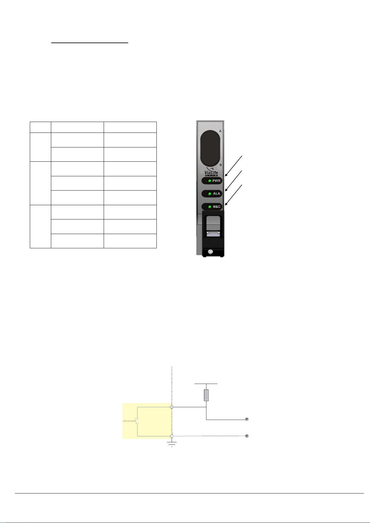
Front panel Indicators, plug in modules2.2.2
Each plug-in module has three front panel LEDs for indication of the state of the module. The following table shows the operation of the front
panel LEDs of the amplifier.
Colour
Plug-in Module
LED1
GREEN
Normal
No light
PSU fail
LED2
GREEN
Normal
Flashing
GREEN
Minor Alarm
RED
Major alarm
LED3
GREEN
I2C enabled
Flashing
GREEN
I2C active
AMBER
I2C disabled
Module summary alarm2.2.3
Each module has a single summary alarm, which registers the status of the module. Activation of this alarm registers an internal fault and the
module should be replaced with a spare and returned to your local ViaLite Communications representative. The alarm state should be
accompanied by a fault status on one of the front panel Status LEDs.
The summary alarm is indicated by use of open drain logic. The alarm logic is OPEN when in an ALARM state and SHORT when in a
NORMAL (non alarm) state. The module will remain in an ALARM state until the ALARM condition is cleared, there is no latching.
Connecting to the summary alarm2.2.4
The alarm output pin should be connected to a suitable current source (a positive voltage via a 10kohm pull-up resistor is adequate). When
the module is in a working (non-alarm) state, the alarm output pin is short circuited to ground by the module. If the module enters an alarm
state, the alarm pin is released to a high impedance state and current is no longer drawn from the constant current source. In the case of a
positive voltage and pull-up resistor, the voltage on the alarm output pin will rise to indicate the alarm state. It follows that, if a module is
removed from the chassis, the alarm will be raised for that module position.
The capability of the open collector is dependent on the module that provides it.
The typical capability of the Open Collector/Drain is 50mA maximum current sink and 15V maximum voltage (Vext)
Vext
Pull up
Resistor
Alarm
Ground
Internal to module External to module

HRS-HB-9 SUPPORT MODULE HANDBOOK.DOCX
10
Module analogue monitor2.2.5
The analogue monitor available on the chassis case connector (see the HRK-3 case handbook) is NOT used by this module. The pin for
these module positions will be open circuit.
Function
Amplifier
Splitter
RF switch
Analogue monitor A
Not Used
Not Used
Not Used
Analogue monitor B
Not Used
Not Used
Not Used
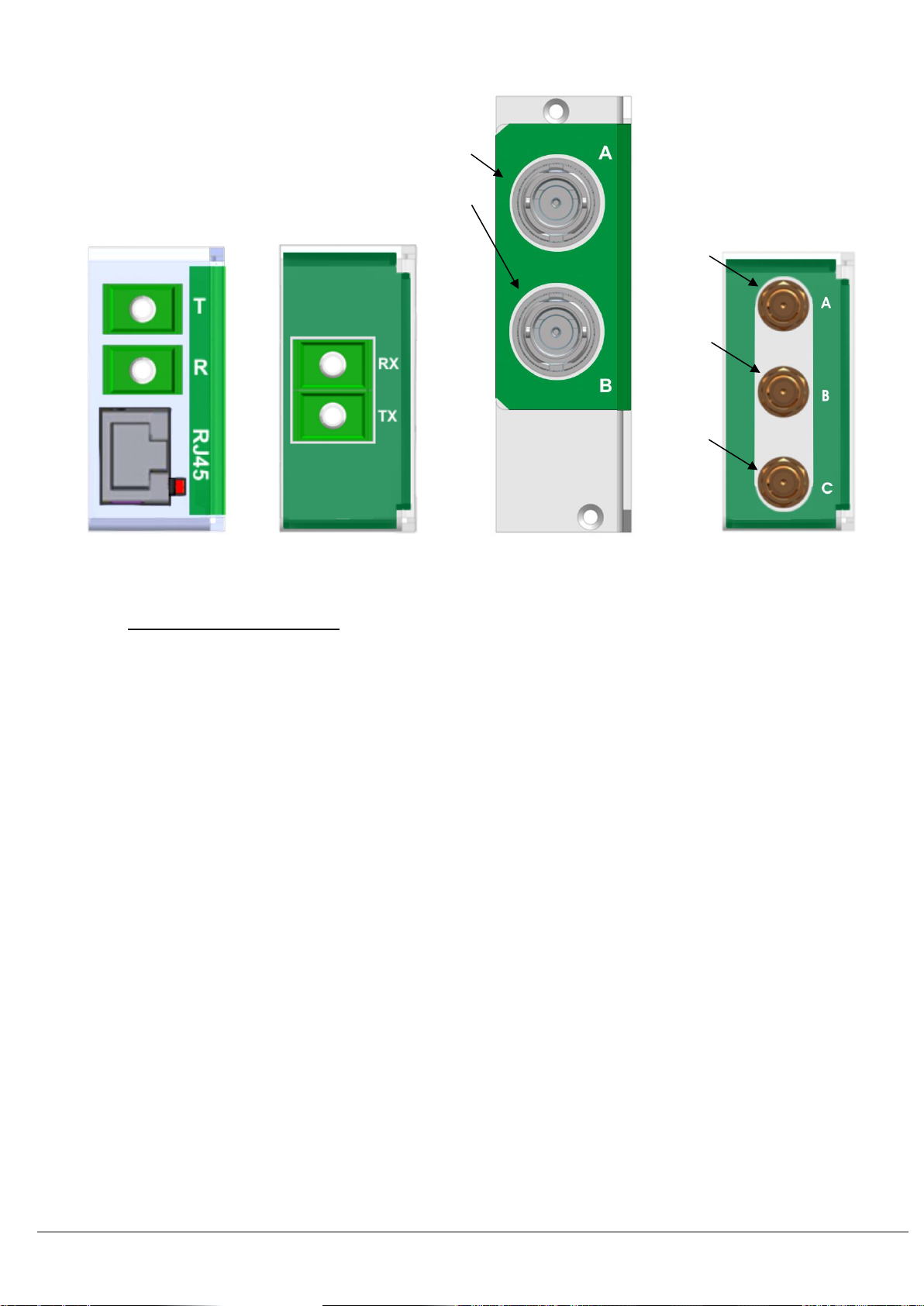
RF connectors2.2.6
ViaLiteHD products are fitted with a range of standard RF connectors. The RF modules are all fitted with FEMALE connectors. When
connecting the modules ensure that you have both the correct type and impedance of connector. Listed below are the connector types
available.
Front panel test connectors, plug in modules only
BNC 50 ohms bayonet
BNC 75 ohms bayonet
Rear Input/Output connectors, plug in modules only
SMA 50 ohms screw on
BNC 75 ohms bayonet
F-Type 75 ohms screw on
Not all connector types are available on all types of module. If you are unsure of the connector type your module is fitted with this can be
determined from the part number (see section 5). Blind mating modules are fitted with a floating RF connector, mating between the plug in
module and the chassis rear plate. This is a purely internal interface and should not be connected by any means other than via the supplied
chassis interface.
Warning! Use of incorrect impedance connectors may also cause intermittent connections and in extreme cases result in
physical damage to the connector.
Warning! Use of incorrect impedance connector will result in mismatch increasing the system loss and reducing flatness.
Warning! Use of incorrect impedance cable will result in mismatch increasing the system loss and reducing flatness.
RF and optical rear input and output ports2.2.7
All modules are fitted with one, two or three rear RF ports. All new Blindmate modules are supplied with an appropriate chassis interface
plate. LEFT and RIGHT refer to connection to adjacent module, referenced to the front view.
Function
Single
Amplifier
Splitter
RF switch
3 port
Port A
RF IN
S1
LEFT
Port B
RF OUT
COMMON
COMMON
Port C
Not
Used
S2
RIGHT
Port D
Not
Used
Not
Used
Not
Used
HRS-HB-9 SUPPORT MODULE HANDBOOK.DOCX
11
Standard rear interface Standard rear interface Blindmate rear interface Standard rear interfac
Gigabit Ethernet Serial Digital Single Amplifier Splitter or switch
Controlling amplifier module2.3
ViaLiteHD RF links are factory preset and ready to operate. However they can be software controlled or manually controlled via the DIP
switches fitted to each module.
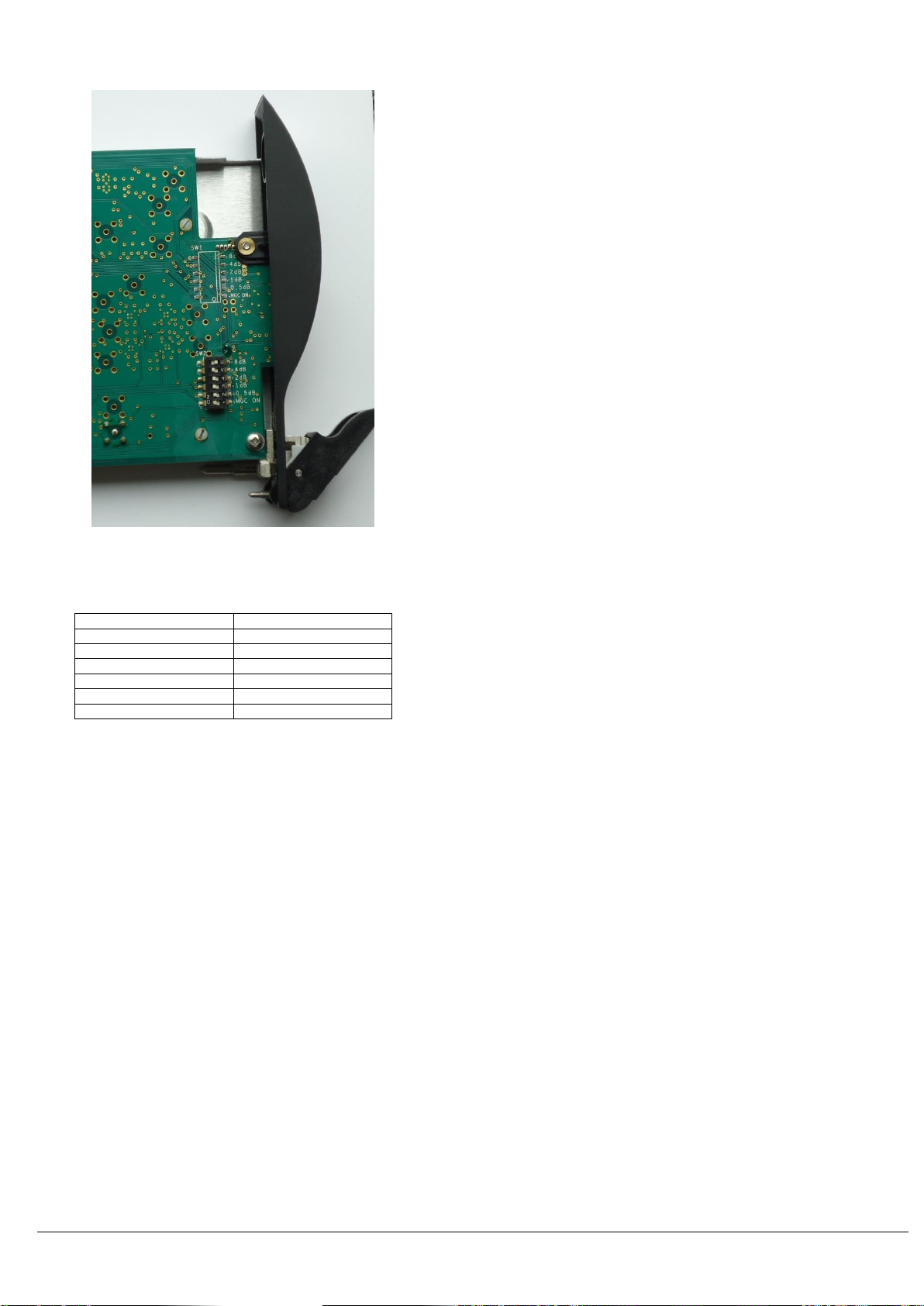
Manual control2.3.1
The Plug-in amplifier modules can be manually configured to set various operational parameters. The dual in line package (DIP) switch SW2
control these configurations, and is located on the bottom side of the PCB and can be accessed by withdrawing the module by approximately
a third of its length
Manual control, DIP switch functions2.3.2
Located on the bottom side of the module board, DIP switch SW2) provides manual control of various functions. SW2 is dedicated to manual
gain control (MGC). Once MGC_ON is switched on, internal RF attenuators can be set directly to a desired level.
All modules will be delivered with DIP switches all set to OFF (clear). Only special manual gain control modules will be delivered with the
DIP switches set to the modules factory calibrated gain settings.
RF port A
RF port A
RF port B
RF port B
RF port C
HRS-HB-9 SUPPORT MODULE HANDBOOK.DOCX
12
Amplifier
Manual Configuration DIP switches
SW2 DIP switch
Single amplifier
All other cards
AMP –8dB
Not fitted
AMP –4dB
Not fitted
AMP –2dB
Not fitted
AMP –1dB
Not fitted
AMP –0.5dB
Not fitted
AMP - MGC ON
Not fitted
Manual switch configurations by module type
When view in the orientation illustrated, switching the DIP to the LEFT is OFF (clear) and to the RIGHT is ON (set)
2.3.2.1 DIP switches, AMPLIFIER AGC
The RF gain of the amplifier is the maximum gain minus the sum of all set AGC steps on SW2.
The RF gain can be changed in nominal steps of 0.5dB.
AMP - MGC ON ON = Module under manual gain control, OFF = Module under software control
AMP - 0.5dB ON = Attenuation increased by 0.5dB nominal, OFF= no gain increase
AMP - 1dB ON = Attenuation increased by 1dB nominal, OFF= no gain increase
AMP - 2dB ON = Attenuation increased by 2dB nominal, OFF= no gain increase
AMP - 4dB ON = Attenuation increased by 4dB nominal, OFF= no gain increase
AMP - 8dB ON = Attenuation increased by 8dB nominal, OFF= no gain increase
2.3.2.2 Manual gain control example
The factory preset maximum gain is 30dB
You wish to decrease the gain to 19dB, a reduction of 11dB from the factory present maximum gain.
The amplifiers AGC setting will be 11dB, made from the following steps 1+2+8, therefore set the switches as shown below
AMP1 –0.5dB=OFF; AMP1 –1dB=ON; AMP1 –2dB=ON; AMP1 –4dB=OFF; AMP1 –8dB=ON.
The new gain is now set to 19dB
Changing modules RF gain2.3.3
The performance specifications in section 6 are only valid for when modules are operated in the factory preset configuration. However the
gain of the modules can be changed to suit customer requirements.

HRS-HB-9 SUPPORT MODULE HANDBOOK.DOCX
13
Software control, via SNMP controller2.3.4
ViaLiteHD support modules can be controlled via a ViaLiteHD SNMP control card fitted in the same chassis; see the SNMP controller
handbook for further details. The control card offers control via both a web interface and SNMP.
Remember if you wish to use software control the manual attenuation has to be set to zero, i.e. all poles with the same switch should return
to OFF position. Failure to do so may prevent the module from controlling the gain correctly.
Susceptibility to DC pulses from ViaLiteHD modules2.4
All amplifier modules will create a 1-2Vpeak DC transient from the RF output at start up into a 50Ω load (approximately 5V into a 1MΩ load).
This may cause failure in some very sensitive spectrum analysers or similar equipment. Please check before connecting your equipment.
Contact ViaLite Communications for more details.
Protection of ViaLiteHD equipment from DC pulses2.5
All modules have AC coupled inputs and/or outputs and will be sensitive to large transients (>5V) applied at the RF connector. This may
result in permanent damage to the modules, particularly to low frequency or wideband modules. Contact ViaLite Communications for more
details.
Module Interface ratings2.6
Logic interface, TTL 5V2.6.1
Absolute maximum voltage rating -0.5 to +5.5V No damage
Input, Logic Low (max) <0.8V
Input, Logic High (min) >2.0V
Output, Logic Low (max) <0.4V no load
Output, Logic High (min) >4.8V no load
Drive capability 1k ohms
Short circuit protection No
Logic interface, RS2322.6.2
Absolute maximum voltage rating -15 to +15V No damage
Input, Logic Low (max) <0.8V
Input, Logic High (min) >2.6V
Output, Logic Low (max) <-3.2V no load
Output, Logic High (min) >+3.2V no load
Drive capability 3k ohms
Short circuit protection Yes
Logic interface, RS422/4852.6.3
Absolute maximum voltage rating -12 to +12V No damage
Input, Logic Low (max) <0.8V Common mode referenced to GND
Input, Logic High (min) >2.0V Common mode referenced to GND
Output, Logic Low (max) <0.8V at 27 ohms Common mode referenced to GND
Output, Logic High (min) >2.0V at 27 ohms Common mode referenced to GND
Output Differential >1.5V at 27 ohms
Output Differential >2.0V at 50 ohms
Drive capability 27 ohms
Short circuit protection Yes
Logic interface, I2C2.6.4
Absolute maximum voltage rating -0.3 to +5.3V No damage
Input, Logic Low (max) <1.5V
Input, Logic High (min) >3.5V
Output, Logic Low (max) <0.6V no load
Output, Logic High (min) >4.3V no load
Drive capability 1k ohms
Short circuit protection No

HRS-HB-9 SUPPORT MODULE HANDBOOK.DOCX
14
Logic interface, Open Drain, output2.6.5
For details of operation see 2.2.4
Operational pull up voltage 0 to 15V No damage
Maximum load current 50mA
Short circuit protection No
Note: Negative voltage on the output will be clamped by the FET body diode; you must ensure that these do not exceed current rating.
Note: When fitted in a chassis with a controller card (i.e. SNMP and web controller or summary alarm card) or if fitted active backplane
(ie SATCOM6) the alarm lines maybe loaded and pulled up, see chassis handbook
Note: When fitted in a chassis or enclosure adjacent to a RF switch or RF splitter card, alarm lines maybe loaded and pulled up, see
chassis handbook
Power interface, Vcc, +12V, input2.6.6
ALL modules EXCEPT High power TX module
Nominal input voltage 12V
Typical input voltage range 11 to 13V
Maximum operational voltage range 9 to 16V
LNB power supply and tone2.6.7
Voltage set to LOW
Nominal output voltage 13.4V, Output select = LOW
Output voltage range 12.4 to 14.4V
Current rating 700mA per channel for single transmit channel (i.e. single transmitter or transceiver module).
350mA per channel for dual transmit channel, 700mA total (i.e. dual transmitter module).
Short circuit protection Yes
Voltage set to HIGH
Nominal output voltage 18.5V, Output select = HIGH
Output voltage range 17.5 to 19.5V
Current rating 700mA per channel for single transmit channel (i.e. single transmitter or transceiver module).
350mA per channel for dual transmit channel, 700mA total (i.e. dual transmitter module).
Short circuit protection Yes
Voltage BOOST active
Nominal output Voltage increased 1V, Output boost = ENABLE
Voltage when set to AUX
Nominal output voltage 22V, AUX mode = ON
Output voltage range 21 to 23V
Current rating 150mA per channel for single transmit channel (i.e. single transmitter or transceiver module).
150mA per channel for dual transmit channel, 300mA total (i.e. dual transmitter module).
Short circuit protection Yes
TONE active
Nominal output level 0.6Vp-p, Tone Gen = ACTIVE
Output range 0.4 to 1.2Vp-p
Nominal frequency 22kHz
Frequency accuracy 20 to 24 kHz
Ethernet interface, GE2.6.8
Fitted the Gigabit Ethernet module
Standard 1000BASE-T, 1GB Ethernet, 802.3
Wiring 4 pairs, use CAT6 or CAT5e cable
Voltage range 0.35 to 3.1V
RJ45 Pin, 8 way
Function
1
P1_0
2
N1_0
3
P1_1
4
N1_1
5
P1_2
6
N1_2
7
P1_3
8
N1_3

HRS-HB-9 SUPPORT MODULE HANDBOOK.DOCX
15
Alarm inputs, switch and splitter2.6.9
These are used by the switch and splitter modules ALARM LEFT and ALARM RIGHT
Load 10Kohms pulled up to +5V
Inputs conditions OKAY condition < 100 ohms to ground
ALARM condition > 100Kohms to ground
No damage voltage -0.5 to +5.5V
RF connectors2.6.10
Maximum RF input power, no damage see rating in section 6 or contact ViaLite Communication
Maximum RF output power see rating in section 6, or contact ViaLite Communication
Optical connections2.6.11
Maximum usable input power see rating in section 6 or contact ViaLite Communication
Optical output power see rating in section 6 or contact ViaLite Communication
HRS-HB-9 SUPPORT MODULE HANDBOOK.DOCX
16
3 Module types
Splitter, module Type3.1
This section covers the following ViaLiteHD RF support module:
RF splitter module
oHRD
The ViaLiteHD RF Splitter / Combiner module allows users to implement 1:1 redundancy with ViaLiteHD RF modules. Together with the
ViaLiteHD dual redundant power supplies and the 1:1 Redundancy RF Switch, the RF Splitter / Combiner provides the highest possible
availability for the ViaLiteHD system. This module is bi-directional and can be used as either a splitter or a combiner.
The ViaLiteHD RF Splitter / Combiner offers the following key advantages:
Low insertion loss
Small 5HP form factor
Blindmate capability
DC pass through on RF ports (switched or unswitched)
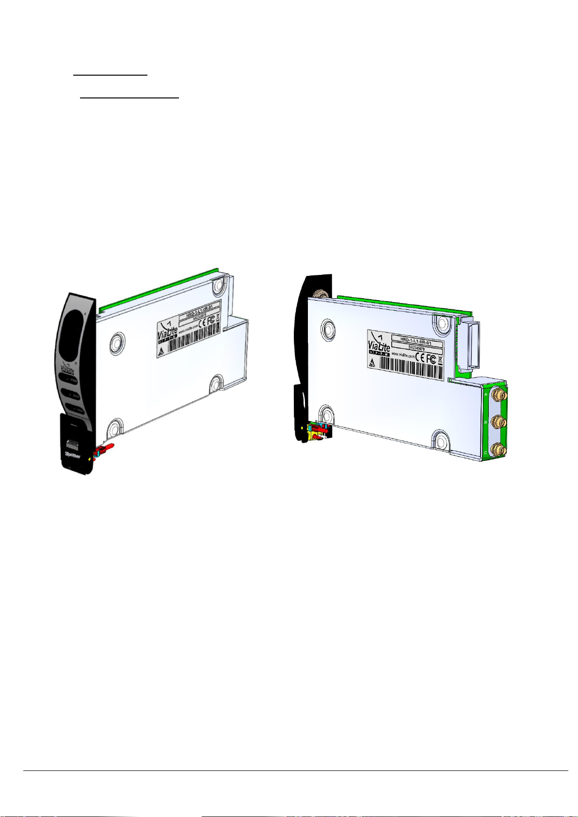
Compatibility with ViaLiteHD chassis
Splitter front view (standard plug-in) Splitter rear view (standard plug-in)
Splitter, options3.1.1
The ViaLiteHD RF Splitter / Combiner module offer the following options
50ohm and 75ohm options
RF connectors
Frequency band
DC pass through
Switched and unswitched DC paths
Standard 5HP module
Blindmate 5HP module
NOTE: Not all combinations of options are available. Contact ViaLite Communications for more details.
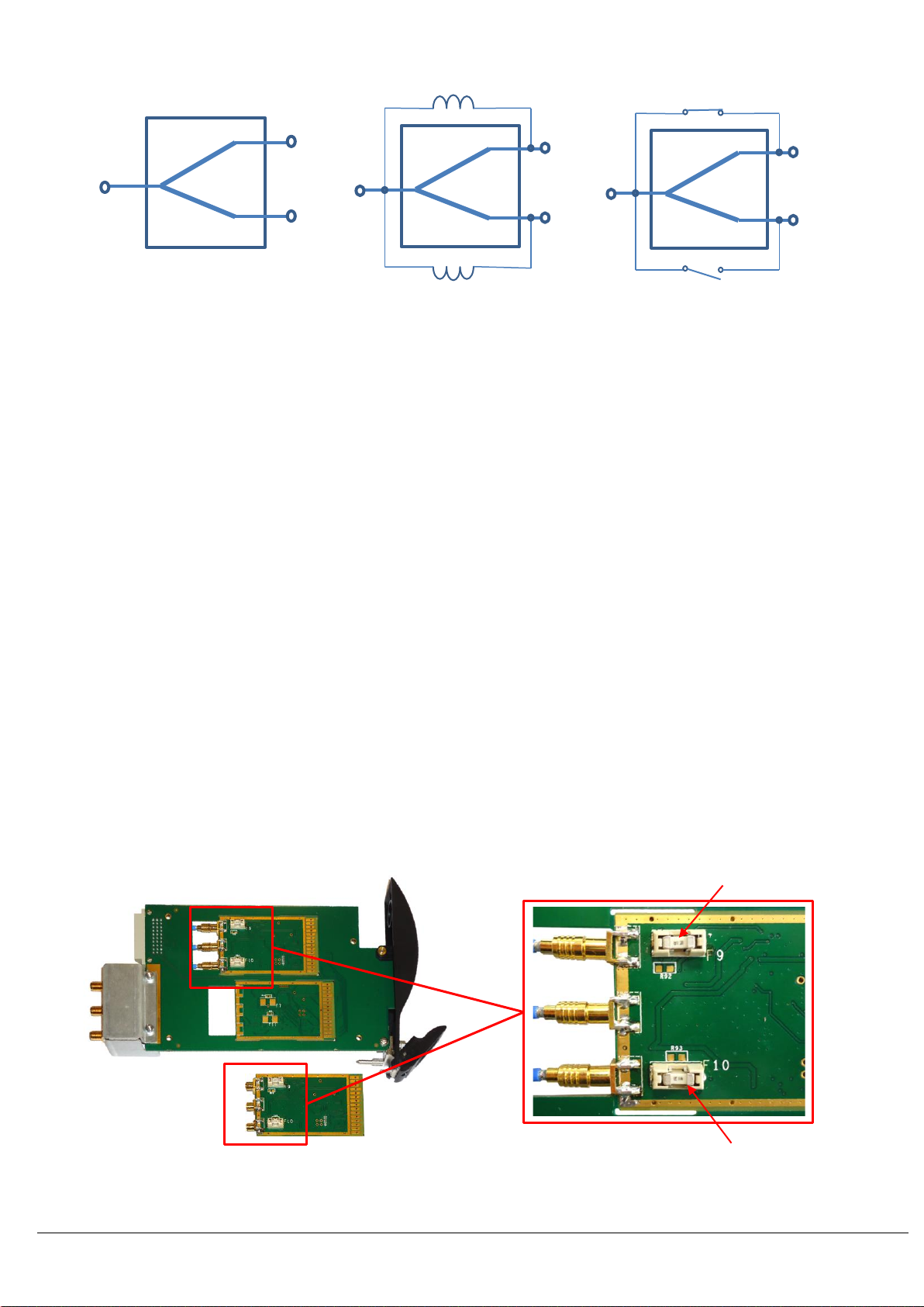
Splitter, DC path3.1.2
The ViaLiteHD RF splitter module can pass DC current. Three variants of the splitter are available.
HRS-HB-9 SUPPORT MODULE HANDBOOK.DOCX
17
The diagrams above shows the difference between DC path options offered.
Splitter with no DC path: All RF ports are DC open circuit
Unswitched DC path: All ports are permanently DC shorted, any DC voltage on one port is available on the others
Switched DC path: The common port is DC connected to one of the output ports dependent on the card configuration, see section 3.1.3
Modules can work with voltages up to 20V and currents up to 0.8A. Unswitched version should be chosen only if DC voltage on all three
ports should be the same. If devices connected to ports S1 and S2 require different voltage or different tone frequency the splitter with
switched DC path should be used.
Note that for the purpose of this manual a term ‘DC path’ means path for low frequency signals from DC to approx. 50 kHz.
Splitter with switched DC path, module configuration3.1.3
The mode in which the RF splitter operates is USER configurable. You can change this by using the ViaLiteHD SNMP and Web controller
module. The DEFAULT configuration in which all units are delivered is PREFERRED LEFT. Below is a list of the available modes.
PREFERRED LEFT –The COMMON is DC connected to the LEFT hand unit, if this unit alarms, it will switch to the RIGHT hand unit.
PREFERRED RIGHT –The COMMON is DC connected to the RIGHT hand unit, if this unit alarms, it will switch to the LEFT hand unit.
FORCED LEFT –The COMMON is DC connected to the LEFT irrespective of alarm status.
FORCED RIGHT –The COMMON is DC connected to the RIGHT irrespective of alarm status.
Note that this is relevant ONLY for DC. RF port behaviour cannot be configured.
Splitter, DC path protection3.1.4
The DC paths of the splitter are protected from over current with a fuse fitted to each DC output path, these protect the passive components
from over stress and permanent damage. The fuses are fast acting “blow once” fuses; these fuses will only fail under gross fault conditions.
The fuse is replaceable –access to the fuse is from the bottom of the module. Contact ViaLite Communications for more details. The
modules are protected as follows.
Splitter with no DC path: No fuse fitted, not required
Unswitched DC path: L-Band HTS, no fuse fitted, DC components will be protected by other system components in standard
configurations.
Unswitched DC path: Other bands, fuse fitted
Switched DC path: Fuse fitted
Position of fuses on rear of splitter modules, plug in and yellow link
RF splitter, no DC path
RF splitter with
unswitched DC path
RF splitter with
switched DC path
Common
Common
Common
S1
S1
S1
LEFT
S2
S2
S2
RIGHT
Fuse F9, port A
Fuse F10, port C
HRS-HB-9 SUPPORT MODULE HANDBOOK.DOCX
18
Splitter, fuse replacement3.1.5
To replace the fuse of the splitter you will need a set of tweezers.
Remove the module from the chassis.
Use a pair of tweezers to remove the failed fuse, pulling perpendicularly away from the PCB.
Fuse F9 is connected to port A
Fuse F10 is connected to port C
NOTE: The fuse is fitted in a socket; see below for a picture of the removable part
Replace the fuse with a suitable part, details below.
Check the fuse is securely fixed.
Replace the module.
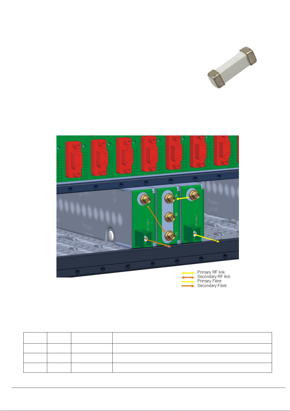
Suitable replacement fuse:
Description: 1A, 125V, very fast, OMNI-BLOK, SMD socketed
PPM part number: 59993A
Source: Littelfuse Suppliers part number: 0453001.MR
Splitter, installation3.1.6
The ViaLiteHD RF Splitter / Combiner module is available in standard plug-in module or blindmate plug-in module; see sections 2.1.1 and
2.1.2 for details on installing these in a chassis. More details are also provided in the chassis handbook HRK-HB. The splitter maybe fitted
in any of the 5HP slots. Your RF splitter can be supplied with two flexible RF cables to be used for the rear panel connections.
Typical configuration of Splitter (standard plug-in) with single transmitter modules, cables omitted for clarity
Splitter, connecting the module3.1.7
The ViaLiteHD RF Splitter / Combiner module has three rear RF ports that connect to the other RF modules being used. Typically an RF
splitter will have its COMMON INPUT port connected to the signal source (such as an LNB output); its OUTPUT S1 port connected to the
PRIMARY fibre optic transmitter input and its OUTPUT S2 port connected to the SECONDARY fibre optic transmitter input.
Function
Splitter
Alarm connection
Notes
Port A
S1
LEFT
Typically this will be the PRIMARY path
Should be connected to the adjacent unit on the left when switched DC path is used
Port B
COMMON
NA
Typically this is an INPUT
Port C
S2
RIGHT
Typically this will be the SECONDARY path
Should be connected to the adjacent unit on the right when switched DC path is used
OMNI-BLOK removable fuse

HRS-HB-9 SUPPORT MODULE HANDBOOK.DOCX
19
In addition, there is a 30-way DIN type connector at the back of the module, which normally plugs into the relevant socket on the chassis
backplane. The pin assignment is given below
30-way DIN
Column A
Function
30-way DIN
Column B
Function
30-way DIN
Column C
Function
A1
NC
B1
ALARM
C1
NC
A2
NC
B2
ALARM LEFT
C2
NC
A3
NC
B3
ALARM RIGHT
C3
NC
A4
NC
B4
NC
C4
NC
A5
NC
B5
NC
C5
NC
A6
NC
B6
MS
C6
NC
A7
NC
B7
SCL
C7
NC
A8
NC
B8
SDA
C8
NC
A9
VCC
B9
VCC
C9
VCC
A10
GND
B10
GND
C10
GND
The Yellow link uses a 30 pin edge connector and the Blue Link uses a 15-way Molex CGRID connector.
Pin, 30 way EDGE connector
Function
Pin, 15 way Blue Link
connector
Function
1, 2
NC
1
NC
3, 4
NC
2
NC
5, 6
NC
3
NC
7, 8
GND
4
GND
9, 10
VCC
5
VCC
11, 12
NC
6
NC
13, 14
NC
7
NC
15,16
NC
8
NC
17, 18
NC
9
NC
19, 20
ALARM LEFT
10
ALARM LEFT
21, 22
NC
11
NC
23, 24
ALARM
12
ALARM
25, 26
ALARM RIGHT
13
ALARM RIGHT
27, 28
SCL
14
SCL
29, 30
SDA
15
SDA
Compatible mating connectors
PPM # Description Supplier Supplier part PPM # Description Supplier Supplier part
number number
55708 CGRID3 15 way housing Molex 90156-0155 59897 Straight connector Toby Electronics 802-S-30-S-R
54245 Crimp connector 22-24AWG Molex 90119-2110 59910 Right angle conn Digikey EEC15DRAN-ND
Note that for the 30 way PCB edge connector, the top and bottom pin pads are electrically connected through the large via holes in the
middle. Hence there are only 15 connections effectively, with 30 pin pads. The PCB connector can be linked to your motherboard through the
via holes using standard 2.54mm pitch pin header.
Splitter, front panel indicators
3.1.8
The ViaLiteHD RF Splitter / Combiner module uses the common front panel signalling scheme detailed in section 2.2.2. It will generate an
ALARM under the condition of an internal hardware failure being detected.
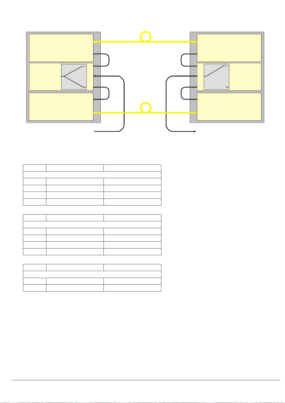
Splitter, system integration3.1.9
In this typical configuration, the RF signal is connected to Port B of the ViaLiteHD RF splitter and the two outputs, ports A and C are fed into
two ViaLiteHD single transmitter modules. These modules are connected via two separate optical fibres to two ViaLiteHD single receiver
modules. These form the PRIMARY and SECONDARY paths. The RF outputs of the PRIMARY and SECONDARY Receivers are
connected to ports A and C respectively of the ViaLiteHD 3 port Switch module. Port B of the ViaLiteHD 3 port Switch module is fed to the
user equipment. Control lines in the chassis backplane connect alarms to adjacent slots. These are used to control the status of the switch
module and ensuring that the RF Switch selects the SECONDARY path in the event of a failure in the PRIMARY path.
Yellow Link: Top View, 30 way double sided header
Connector Type: 2.54mm double sided edge
connector
2927252321191715131197531
Contact No 1
Blue Link module: Top view, 15 pin header
(male)
Connector Type: Molex (C-Grid III), single
Contact No 1
HRS-HB-9 SUPPORT MODULE HANDBOOK.DOCX
20
Typical 1:1 redundancy configuration
In this example configuration, the following parts would be required to implement the system.
Quantity
Description
Part Number
Remote chassis
1
Chassis
HRK3S
2
PSU
HPS
2
L-Band HTS single transmitter
HRT-L1-8D-53-S1310
1
RF Splitter
HRD-1-L1-0D-41
Quantity
Description
Part Number
Local chassis
1
Chassis
HRK3S
2
PSU
HPS
2
L-Band HTS single receiver
HRR-L1-8D-03
1
3 port RF switch
HRS-1-L1-0D-01
Quantity
Description
Part Number
Cabling
2
Fibre optic cable
F8R1/x
4
RF cable
73739
Splitter, 3U chassis configurations, four 1:1 redundant receivers3.1.10
The chassis configuration below can be used to provide four redundant transmitters in a single ViaLiteHD 3U chassis. For simplicity the
chassis configuration is viewed from the rear.
The blank slot can be used as a storage slot for a hot spare.
For simplicity the chassis configuration is viewed from the rear.
A
C
PRIMARY FOLTX
SECONDARY FOLTX
A
A
RF INPUT (LNB)
B
PRIMARY FOL RX
SECONDARY FOL RX
A
RF SPLITTER
RF OUTPUT (satcom receiver)
A
C
A
B
AA
AA
PRIMARY
fibre optic
cable
SECONDARY
fibre optic
cable
Remote rack chassis Local rack chassis
RF SWITCH
This manual suits for next models
16
Table of contents
Other PPM Control Unit manuals


Popular Control Unit manuals by other brands


M-Elec
M-Elec ADB-5F30v1 instruction manual

Power Tec
Power Tec Regenerative Brushless DC Motor Control... Installation and operation instruction manual

Sel
Sel 651R installation instructions

Lake Shore
Lake Shore 240 Series quick start guide

American Flow Control
American Flow Control 2500 Series product manual

Honeywell
Honeywell NetAXS-123 installation guide


