Lake Shore 240 Series User manual

1Model 240 Quick Start Guide
Quick Start Guide
240 Series Cryogenic Sensor Input Module

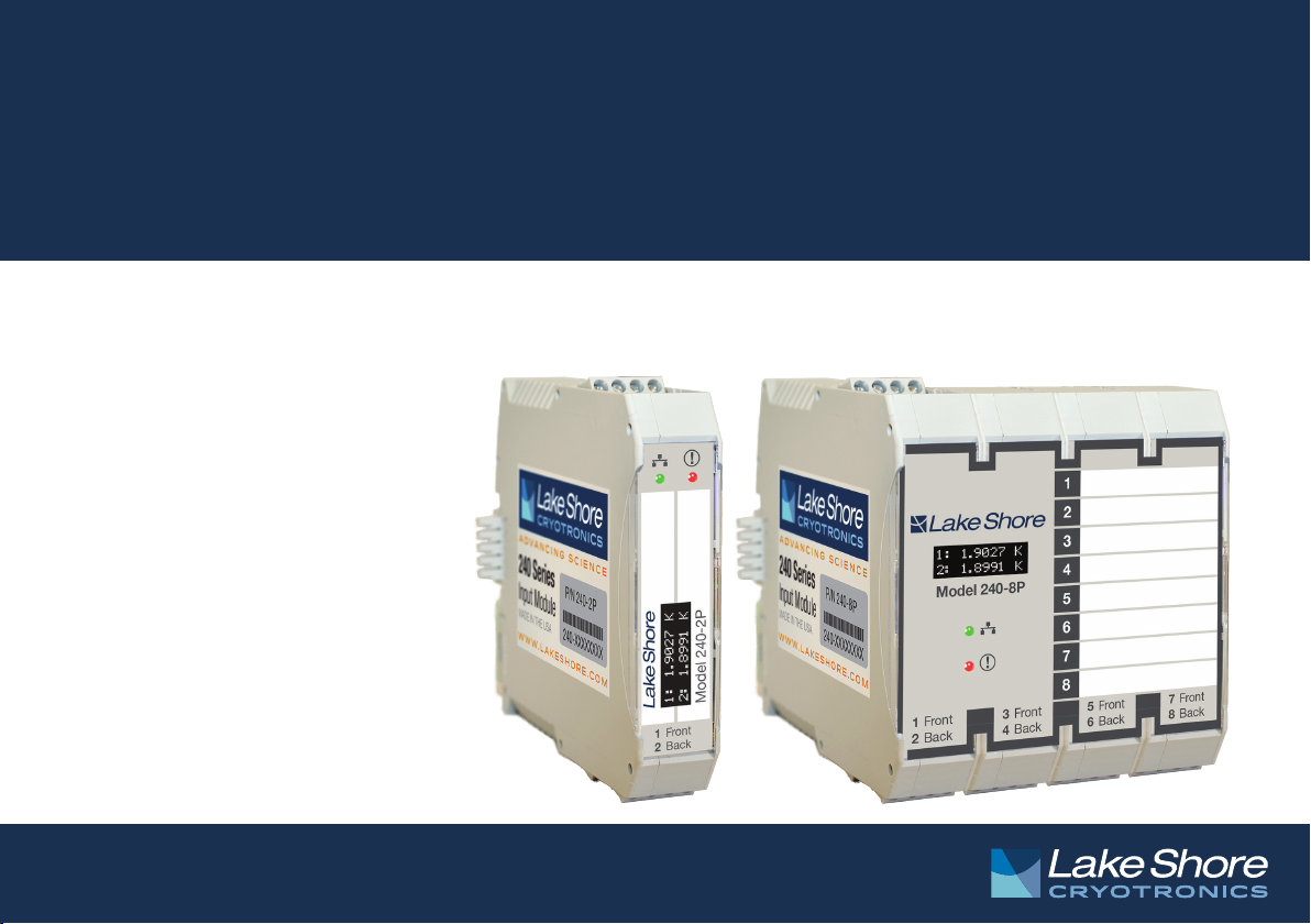
2Model 240 Quick Start Guide
Safety Precautions
Observe these general safety precautions during all phases of
instrument operation, service, and repair. Failure to comply with
these precautions or with specic warnings in the user’s manual
violates safety standards of design, manufacture, and intended
instrument use. Lake Shore Cryotronics, Inc. assumes no liability
for customer failure to comply with these requirements.
The 240 Series input module protects the operator and
surrounding area from electric shock or burn, mechanical
hazards, excessive temperature, and spread of re from the
instrument. Environmental conditions outside of the conditions
below may pose a hazard to the operator and surrounding area.
Indoor use
Altitude to 2000 m
Temperature for safe operation: -20 °C to 50 °C
Maximum relative humidity: 95% non-condensing
Power supply voltage uctuations not to exceed
±10% of the nominal voltage
Overvoltage category II
Pollution degree 2
IP20: not protected against harmful ingress of water
Ground the instrument
To minimize shock hazard, the instrument is equipped with a
grounded connection to the DIN rail. Connect the DIN rail to an
electrical ground.
Do not operate in an explosive atmosphere
Do not operate the instrument in the presence of ammable gases or
fumes. Operation of any electrical instrument in such an environment
constitutes a denite safety hazard.
Do not substitute parts or modify instrument
Do not install substitute parts or perform any unauthorized
modication to the instrument. Return the instrument to an
authorized Lake Shore Cryotronics, Inc. representative for service and
repair to ensure that safety features are maintained.
Cleaning
Do not submerge instrument. Clean only with a damp cloth,
exterioronly.
Installation
When installing the instrument, ensure it is mounted securely on the
DIN rail.
Improper Use
If the instrument is used in a manner that is not specied by Lake
Shore, the safety protections provided by the instrument are no
longer guaranteed, and may be impaired.
Refer to the Model 240 user’s manual for more safety information.

3Model 240 Quick Start Guide
Introduction
This guide provides basic
information for getting started
with your input modules. For
further information, please see
the Model 240 user’s manual.
Front-mounted
OLED screen
Cryogenic temperature
sensor inputs
(5-pin connectors)
Power and communication
connector (4-pin connector)
USB port
USB port
Integrated
rear DIN rail
connections

4Model 240 Quick Start Guide
Unpacking
1. Inspect shipping containers for external damage
before opening them.
2. Photograph any container that has signicant
damage before opening it.
3. Inspect all items for both visible and hidden damage
that occurred during shipment. If there is visible
damage to the contents of the container, contact the
shipping company and Lake Shore immediately.
NOTE: Procedures vary slightly with shipping
companies. Keep all damaged shipping materials and
contents until instructed to either return or discard
them.
4. Open the shipping container and keep the container
and shipping materials until all contents have been
accounted for.
Packing list
Items included with Model 240 input module:
240 Series input module
2 or 8 sensor input connectors, 5-pin terminal plug
connectors
1 power and communication connector, 4-pin
terminal plug connector
1 or 4 DIN rail backplane connector, 5-pin 35 mm DIN
rail connectors
NOTE: For further information, see section 3.2.1 of the
Model 240 user’s manual.

5Model 240 Quick Start Guide
Power and Communication
Connection
To minimize shock hazard, the instrument is equipped
with a grounded connection to the DIN rail. Connect the
DIN rail to an electrical ground.
Power
The typical power supply is 24 VDC, but can range
from 21.6 VDC to 26.4 VDC. The power supply should be
capable of supplying at least 100 mA per module.
PROFIBUS interface
The PROFIBUS-DP communication integrates with
distributed PLC-based control architectures.
Sensor Input Connection
For best results, voltage leads (V+ and V-) and current
leads (I+ and I-) should be twisted together. The twisted
pairs of voltage and current leads should then be
covered with a braided or foil shield that is connected
to the shield pin of the instrument. This type of cable is
available through local electronics suppliers. Instrument
specications are given assuming 3 m
(10 ft) of sensor cable. Longer cables can be used, but
environmental conditions may degrade accuracy and
noise specications.
The sensor inputs are isolated from earth ground to
reduce noise pickup. The shield should not be connected
to earth ground at the modules. One shield should
be connected to an earth ground near the sensors.
Connecting at more than one point will cause a ground
loop, which adds noise to the measurement.
PWR+ DC power supply positive
PWR- DC power supply return
B+ PROFIBUS signal
A- PROFIBUS signal
I+ Positive current
V+ Positive voltage
SH Shield
V- Negative voltage
I- Negative current

6Model 240 Quick Start Guide
NOTE: Make sure to properly seat connectors.
When removing a sensor, use a screwdriver to gently
remove the connector.
USB Connection
MeasureLINK™ utility
Lake Shore provides a utility called MeasureLINK™,
which makes loading temperature curves into the
Model 240 a very simple process. The program
congures the module and copies curves from
formatted les into the Model 240.
Congure the USB/PC connection
The Model 240 is fully-congurable through direct USB
connection.
NOTE: After conguring the USB, disconnect it from the
computer before beginning PLC communication.
Physical Installation
The 240 Series input module has been specically
designed to mount on a DIN rail. To minimize shock
hazard, the instrument is equipped with a grounded
connection to the DIN rail. Mount the input module
vertically, and connect the DIN rail to an electrical
ground. If the input module is mounted in an equipment
rack or enclosure, ensure that the ambient temperature
does not exceed the instrument rating.
NOTE: For best noise and accuracy performance, install the
input module in a grounded metallic enclosure.
Power and PROFIBUS
connections may be
shared between
modules by using
the optional
backplane
connectors supplied
with the module.

7Model 240 Quick Start Guide
Startup
Once you have placed the Model 240 in its intended
location, you can begin setting up the instrument. The
steps that follow will take you through to displaying
measurements. This is just the beginning of what is
possible with the Model 240. For additional features,
please see the Model 240 user’s manual.
Basic operation
1. Connect a power adapter to the input module.
2. Connect the USB connector to the computer using a
USB cable.
3. Install and run the MeasureLINK™ utility.

8Model 240 Quick Start Guide
4. Select the input module from the drop down menu and click Connect.
5. Click the Input at the left of the screen to congure the sensor settings.

9Model 240 Quick Start Guide
6. Load the sensor calibration le (under Sensor setup) that matches the sensor by navigating to the
appropriate le.

10 Model 240 Quick Start Guide
Type of sensor
Custom curve Cernox
Standard curve Platinum/Diode
No curve Simulated
If you have a custom calibration curve to load, choose Custom Curve and load your le (the Model 240
supports the .340 le format).
If a sensor with a standard curve is connected, choose Standard Curve and select the curve from the drop
down menu.
If you aren’t using a curve, the module will continue to monitor sensor units.
7. Once the curve is loaded, rename the Input Label (if desired).
8. Turn Sensor Excitation to ON. (Turn Sensor Excitation to off to disable any unused inputs.)
9. Under Operating mode, select High accuracy or High speed.
NOTE: The Current Reversal option is available if a resistive sensor is connected, and the High accuracy mode is selected.
NOTE: High speed ID is only available for the Model 240-2P.
10. Under Reporting units, select either Sensor units or a temperature unit.
11. Live readings from your connected sensors should now be displayed at the right of the screen, as well as on the
front OLED display of the 240 Series input module.

11 Model 240 Quick Start Guide
12. Click Module to go to the Module Settings screen, and set the PROFIBUS address on the main screen of the
MeasureLINK™ utility.
NOTE: For further information on communication settings, see section 4.3.3.2 of the Model 240 user’s manual.
13. Your module should now be congured to respond to PROFIBUS requests, and you may disconnect the Model
240 by clicking the Disconnect button.
Evaluation Kit
The evaluation kit includes two unique accessories for the 240 Series input module that will help simulate a live
sensor connection if one is not readily available for your evaluation testing.
Sensor simulator: A box containing a trimpot (variable resistor) that is similar to the Cernox temperature range, to be
used as a rough approximation of these sensors. This product can be useful if you’d like to see how the 240 Series
input module handles communicating and displaying a particular temperature range, or if you’d like to see how the
240 Series input module autoranges. Follow these steps to use the sensor simulator:
1. Connect the sensor simulator to the desired input of the 240 Series input module using the pluggable connector.
2. In MeasureLINK™, choose the correct input.
3. Under Sensor setup, select Standard Curve and pick Sensor Simulator – NTC from the drop down list.
4. Make any other changes to the input conguration needed for your application, and then disconnect from
MeasureLINK™.
5. Adjust the dial to change the temperature to coincide with the markings on the sensor simulator box.
NOTE: The accuracy rating of the trimpot is 10%, so the measured resistance and temperature value may not align exactly
with the markings on the dial. Please do not use the sensor simulator as a method for verifying accuracy of the 240 Series
input module.

12 Model 240 Quick Start Guide
Fixed resistor board: A small PCB containing two different xed resistors that correspond with an arbitrary Cernox
sensor at approximately 1.8 K and a 100 W platinum sensor at approximately 65 K. The evaluation kit contains
enough of these boards for both the 2 and 8 input modules included in the kit so that valid readings can be easily
obtained on all inputs. Follow these steps to use the xed resistor board:
1. Insert one of the xed resistor boards into one of the 5-pin sensor input connectors provided with the 240
Series input module. Locate the board so that the switch is on the same side as the screw heads on the terminal
connector.
2. Screw down the terminal connections so that the terminals contact the metal traces on the ngers of the xed
resistor board.
NOTE: The ngers can be fragile. Please handle the assembled set by the terminal connector when connecting and
disconnecting to the 240 Series input module.
3. Plug the terminal connector into the desired input of the 240 Series input module. The switch should face toward
the front of the module.
4. In MeasureLINK™, choose the correct input.
5. Under Sensor Setup, select the sensor you wish to simulate from the drop down list under Standard Curve:
For Cernox reading 1.8K, choose Sensor Simulator – NTC
For Platinum reading 65 K, choose LSCI PT-100
6. Make any other changes to the input conguration needed for your application, and then disconnect from
MeasureLINK™.
7. Set the switch on the xed resistor board to CERNOX if you loaded the Sensor Simulator – NTC temperature
curve. Set the switch to PLATINUM if you selected the LSCI PT-100 curve instead.
NOTE: If the switch is set to PLATINUM when the Sensor Simulator – NTC curve is loaded, the temperature displayed
will be approximately 400 K. If the switch is set to CERNOX when the LSCI PT-100 curve is loaded, the input module will
report an S.Over error since the resistance value is greater than the 1 kW limit for a PTC sensor.

13 Model 240 Quick Start Guide
Analog input
Cernox Platinum Diodes
Sensor units Ohms (Ω) Volts (V)
Cernox Platinum Diodes
Measurement
range
0 to 100kΩ 0 to 1 kΩ 0 to 10 V
Excitation
current
100 nA to
1 mA
1mA 10 µA
Measurement performance:
Measurement
resolution
Electronic
accuracy
2 K (with CX-1050) 0.06 mK ±0.57 mK
4.5 K (with CX-1050) 0.2 mK ±2.1 mK
4.2 K (with DT-670) 0.6 mK ±15 mK
77 K (with PT-103) 47 mK ±104 mK

14 Model 240 Quick Start Guide
Contacting Lake Shore
The Lake Shore Service Department is staffed Monday through Friday between the hours of 8:00 a.m. and
5:00p.m.EST, excluding holidays and company shut down days.
Contact Lake Shore Service through any of the means listed below. However, the most direct and efcient way is to
complete the online service request form at http://www.lakeshore.com/Service/.
Lake Shore Service
Lake Shore Cryotronics
Instrument Service Department
575 McCorkle Blvd.
Westerville, Ohio USA 43082-8888
Phone: 614-891-2244
Email: service@lakeshore.com
Web: www.lakeshore.com
Rev. 1.2 PN 119-240 9 September 2016
Other manuals for 240 Series
1
This manual suits for next models
2
Table of contents
Other Lake Shore Control Unit manuals
Popular Control Unit manuals by other brands

Val-Matic
Val-Matic Swing-Flex Check Valve Operation, maintenance and installation manual

Thermotron
Thermotron 8200 Plus instruction manual

Pepperl+Fuchs
Pepperl+Fuchs VAA-2E-KE1-S Original instructions

Honeywell
Honeywell REDLINK ERM5220R Product data

LGB
LGB 55080 manual

Luxart
Luxart OmniVersa 1341-DIV Installation