PPM ViaLiteHD HRK-12 HB-5 Series User manual

ViaLiteHD
1U GPS Splitter
User Manual
GPS Splitter
HRK-12-x-HB-5
CR5266 02/03/23
Pulse Power & Measurement Ltd
, 65 Shrivenham Hundred Business Park, Watchfield, Swindon, Wiltshire SN68TY, UK
Tel +44 (0)1793 784389 Fax +44 (0)1793 784391 Email sales@vialite.com Web www.vialite.com

HRK-12-X-HB-5 VIALITEHD 1U GPS SPLITTER HANDBOOK.DOCX
2
Instrument Care and Safety Information
Please read the whole of this section before using your ViaLiteHD product. It contains important safety
information and will enable you to get the most from your Fibre Optic link.
Electrical Safety
The ViaLiteHD chassis provides the termination for power inputs and can be fitted with power supplies.
The ViaLiteHD chassis is a Safety Class 1 product (having metal chassis directly connected to earth via the power
supply cable).
NOTE: Before removing ANY of the POWER SUPPLIES the power to that position MUST be ISOLATED (i.e. AC
power is not applied to its inlet connectors). ViaLite Communications ships all units fitted with a single power supply
with a blanking plug in the unused AC inlet, to prevent power being applied to that position; the HPS-1-0 blanking plug
must not be removed unless a power supply is fitted.
When operating the equipment note the following precautions:
Hazardous voltages exist within the equipment.
There are no user serviceable parts inside; the covers MUST NOT be removed.
There are no user replaceable fuses in the chassis mounted equipment. Replacement should only be carried out
by a ViaLite Communications technician.
The chassis earth stud SHOULD be connected to the safety earth.
When using a 2 pin power supply cable the chassis earth stud MUST be connected to the safety earth.
The ViaLiteHD Power Supply Modules do not have an isolating switch on the mains voltage inlet. For this reason,
the ViaLiteHD chassis MUST be installed within easy reach of a clearly labelled dual pole mains isolation switch,
which supplies the equipment.
PSU modules fused on one input feed (see section 5), should be externally fused on both inputs if the polarity of
the connectors could be reversed; rating should match those given in section 5.3.
ESD Precautions
The ViaLiteHD 1U chassis is equipped with active electronics and will be fitted with additional active modules while in
use.
Precautions for handling electro-static sensitive devices should be observed when handling all ViaLiteHD modules.
Technicians should ensure that they use effective personal grounding (i.e. ESD wrist strap etc.) when servicing the
equipment. Any equipment or tools used should be grounded to prevent static charge build-up. Good practice should
be observed at all times. For reference see relevant standards.
EN 61340-5-1, “Protection of Electronic Devices from Electrostatic Phenomena – General Requirements”
Optical Safety
The ViaLiteHD RF Transmitter and Transceiver modules contain laser diode sources operating at nominal
wavelengths of 1270nm to 1610nm.
These devices are rated as EN60825-1 CLASS 1 radiation emitting devices. A class 1 laser is safe under all conditions
of normal use.
When operating the equipment note the following precautions:
Never look into the end of an optical fibre directly or by reflection either with the naked eye or through an optical
instrument.
Never leave equipment with radiating bare fibres – always cap the connectors.
Do not remove equipment external covers when operating.
Hot surface
The ViaLiteHD Redundancy load module may have hot surfaces when operating under fulll load. The hot surfaces are
not accessible when fitted in an approved chassis installation.
Suitable precaution should be taken when handling this device.
Allow to cool for 10 minutes
Do not touch metallic surfaces or printed circuit board when hot.
When handling, hold front panel and handle only.
NOTE: THIS EQUIPMENT IS NOT SUITABLE FOR USE IN LOCATIONS WHERE CHILDREN ARE LIKELY TO BE PRESENT

HRK-12-X-HB-5 VIALITEHD 1U GPS SPLITTER HANDBOOK.DOCX
3
TABLE OF CONTENTS
1 INITIAL INSPECTION ............................................................................................................................................................................ 4
2 INTRODUCTION TO THE VIALITEHD RANGE ..................................................................................................................................... 4
3 VIALITEHD GPS SPLITTER .................................................................................................................................................................. 5
3.1 Description ................................................................................................................................................................................. 5
3.1.1 GPS blind mate RX modules. ........................................................................................................................................ 5
3.1.2 Redundant AC Version. ................................................................................................................................................. 5
3.1.3 Redundant DC Version. ................................................................................................................................................. 5
3.2 Power Interface Management .................................................................................................................................................... 6
3.2.1 External backplane power ............................................................................................................................................. 6
3.2.2 Module bias feed ........................................................................................................................................................... 6
3.3 Alarm Management ................................................................................................................................................................... 6
3.3.1 Common Chassis 25way Connector J1 ......................................................................................................................... 6
3.3.2 Connecting to an "open collector" output. ...................................................................................................................... 6
3.3.3 Summary Alarm............................................................................................................................................................. 6
3.3.4 Module Alarm Defeat ..................................................................................................................................................... 7
3.4 Heat management ..................................................................................................................................................................... 7
3.5 Unused module positions ........................................................................................................................................................... 7
3.6 Minimum power supply load ....................................................................................................................................................... 8
3.7 Chassis Specification ................................................................................................................................................................. 9
3.8 Chassis connector pinouts ......................................................................................................................................................... 9
3.9 LNA feed simulation ................................................................................................................................................................. 10
4 INTEGRAL VIALITEHD HRC-3 MODULE ............................................................................................................................................ 10
4.1 Software Update ...................................................................................................................................................................... 10
4.2 Reset Button ............................................................................................................................................................................ 10
5 VIALITEHD POWER SUPPLIES .......................................................................................................................................................... 10
5.1 Slide in Chassis AC Power Supplies, HPS-1-GPS ................................................................................................................... 10
5.2 Slide in Chassis DC Power Supplies, HPS-1-GPS-DC ............................................................................................................. 11
5.2.1 Fuse replacement in DC Power Supplies..................................................................................................................... 12
5.3 Specification ............................................................................................................................................................................ 13
5.4 19” Chassis Power Requirements ............................................................................................................................................ 14
6 INSTALLATION GUIDE ....................................................................................................................................................................... 15
6.1 Chassis Installation .................................................................................................................................................................. 15
6.2 Power Supply Module Installation (slots 4 and 5) ..................................................................................................................... 15
6.3 GPS RX Plug-in Modules (slots 1-2) ........................................................................................................................................ 15
6.4 5HP blanking panel installation ................................................................................................................................................ 17
6.5 Power supply blanking panel installation (slots 4, 5)................................................................................................................. 17
6.6 Electrical power connection ..................................................................................................................................................... 17
6.7 Fibre Connections .................................................................................................................................................................... 17
6.8 SNMP Fibre Connections......................................................................................................................................................... 18
6.9 SNMP Ethernet Connections ................................................................................................................................................... 18
6.10 GPS connection ....................................................................................................................................................................... 18
7 PART NUMBERING ............................................................................................................................................................................. 19
8 MAINTENANCE AND FAULT-FINDING GUIDE ................................................................................................................................... 20
9 PRODUCT WARRANTY ...................................................................................................................................................................... 21
10 FCC APPROVAL ................................................................................................................................................................................. 21

HRK-12-X-HB-5 VIALITEHD 1U GPS SPLITTER HANDBOOK.DOCX
4
1 Initial Inspection
Unpack and inspect the equipment as soon as possible. If there is any sign of damage or any parts missing, do not install the equipment
before seeking advice from ViaLite Communications or your local agent.
The equipment received should match the delivery note that is shipped with the equipment. If there are any discrepancies, contact ViaLite
Communications or your local agent.
Check that ALL unfitted POWER SUPPLY positions are ISOLATED (i.e. AC power is not applied to its inlet connectors). ViaLite
Communications ships all chassis fitted with a single power supply, with a blanking plug in the unused AC inlet; to prevent power being applied
to that position the HPS-1-0 blanking plug must NOT be removed unless a power supply is fitted. Failure to do this will cause a potential
electrical hazard.
2 Introduction to the ViaLiteHD Range
The ViaLiteHD range has been developed to provide a modular solution to the transmission of a wide range of analogue and digital data where
traditional ‘copper wire’ systems cannot be used, for example, in electrically noisy environments or over long distances
The range is ideal for permanent and semi-permanent installation in satellite communications, GPS, antenna remoting and other related
applications.
The variety of links available includes low frequency timing (2kHz) to wideband RF (4.2GHz), RF splitters, amplifiers and RF switches; they
also include a full suite of supporting functions including RS232/422/485, Ethernet and control systems to monitor and control the system with
both Web and SNMP interfaces.
All ViaLiteHD equipment operates over high quality glass fibre optic cable, which can be supplied in low-cost 3mm jacket, riser and outdoor
specifications. The links can also be used with existing cable systems at customer premises.
A ViaLiteHD system can be added to at any time, enabling the system to evolve with the needs of the user.
ViaLiteHD is a product brand manufactured by Pulse Power and Measurement Ltd (PPM). ViaLite Communications is a division of Pulse
Power and Measurement Ltd (PPM).
HRK-12-X-HB-5 VIALITEHD 1U GPS SPLITTER HANDBOOK.DOCX
5
3 ViaLiteHD GPS Splitter
3.1 Description
The GPS Splitter is a 19” rack mount 1U chassis, the chassis must be factory configured for either AC or DC power. Power supplies MUST
match the chassis type (either AC or DC) failure to do so may result in permanent damage to your system. The modules fitted in the chassis
must be either single or dual output blind mate GPS RX modules – Section 3.1.1.
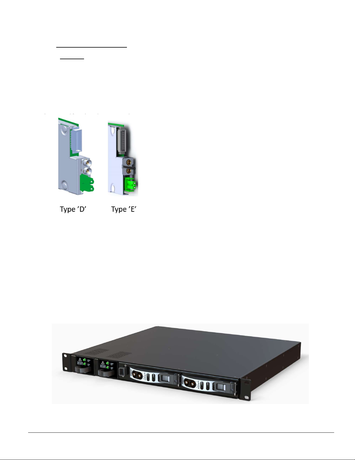
3.1.1 GPS blind mate RX modules.
The modules fitted in your Splitter chassis will either be Type ‘D’ or Type ‘E’ to identify which you have refer to the pictures below: The type
‘E’ is the newer style module. It should be noted that because of the different RF and fibre connectors the two are not interchangeable. Should
you wish to upgrade your Splitter rack then please contact PPM to discuss your requirements and availability of modules.
There are two factory configured powered versions;
3.1.2 Redundant AC Version.
Depending on part number selection the chassis will ship with two power modules fitted and both AC inputs accessible or a single power supply
with a blanking plug in the unused AC inlet, to prevent power being applied to that position; the HPS-1-0 blanking plug must not be removed
unless a power supply is fitted in the relevant power supply slot.
3.1.3 Redundant DC Version.
Depending on part number selection the chassis will ship with two power modules fitted and both DC inputs accessible or a single power supply
however both DC inputs will still be accessible, care should be taken when connecting the DC inputs to ensure a power supply is fitted in the
relevant power supply slot.
The chassis dual power supply configuration provides full redundancy and maximum reliability to avoid GPS signal loss in the event of a power
supply failure. Before removing any power supply, the input power must be isolated from that module.
Note: Each power supply position requires a separate power source to provide fully redundant protection.
GPS Splitter Rack accommodates up to two single or dual GPS RX modules and one embedded control module and two front mount power
supplies
Table of contents
Other PPM Media Converter manuals

Popular Media Converter manuals by other brands


H&B
H&B TX-100 Installation and instruction manual

Bolin Technology
Bolin Technology D Series user manual

IFM Electronic
IFM Electronic Efector 400 RN30 Series Device manual

GRASS VALLEY
GRASS VALLEY KUDOSPRO ULC2000 user manual

Linear Technology
Linear Technology DC1523A Demo Manual

Lika
Lika ROTAPULS I28 Series quick start guide

Weidmuller
Weidmuller IE-MC-VL Series Hardware installation guide

Optical Systems Design
Optical Systems Design OSD2139 Series Operator's manual

Tema Telecomunicazioni
Tema Telecomunicazioni AD615/S product manual

KTI Networks
KTI Networks KGC-352 Series installation guide

Gira
Gira 0588 Series operating instructions

Lika
Lika SFA-5000-FD user guide