Visa Lighting SYMMETRY Series User manual

SYMMETRY
CM1970-W
CM1972-W
CM1972-T
Drawing:
762262XX
Rev:
A
Sheet:
1 of 6
Eng:
CG2
Date Drawn:
1/11/17
INSTALLATION INSTRUCTIONS
Model:
CM1970-W, CM1972-W, CM1972-T
Fixture Family:
SYMMETRY
1717 West Civic Drive Milwaukee, WI 53209
414-354-6600
Design Modification Rights Reserved
© Visa Lighting
!
When using electrical equipment, basic safety precautions should always be followed, including the following:
Read all instructions carefully before installing and save for future use.
•
Make sure all connections are in accordance with the National Electrical Code and local regulations.
•
To avoid possible electric shock, be sure the power supply is turned off before servicing or installing the fixture
•
Service should be performed by qualified personnel.
•
These instructions may not cover all details or variations. If additional information is needed, please contact Visa Lighting.
•
Document Description: Installation Instructions for
Symmetry Series Luminaires

LENS ASSEMBLY
TRIM FRAME
LED HOUSING
LENS SPRING
TRIM FRAME SCREWS
.281 MOUNTING HOLE
(4) PLACES
18.0
SQUARE
LENS AND TRIM FRAME ASSEMBLY
Mounting Hole Layout
Drawing:
762262XX
Rev:
A
Sheet:
2 of 6
Eng:
CG2
Date Drawn:
1/11/17
INSTALLATION INSTRUCTIONS
Model:
CM1970-W, CM1972-W, CM1972-T
Fixture Family:
SYMMETRY
1717 West Civic Drive Milwaukee, WI 53209
414-354-6600
Design Modification Rights Reserved
© Visa Lighting
!
When using electrical equipment, basic safety precautions should always be followed, including the following:
Read all instructions carefully before installing and save for future use.
•
Make sure all connections are in accordance with the National Electrical Code and local regulations.
•
To avoid possible electric shock, be sure the power supply is turned off before servicing or installing the fixture
•
Service should be performed by qualified personnel.
•
These instructions may not cover all details or variations. If additional information is needed, please contact Visa Lighting.
•
Document Description: Installation Instructions for
Symmetry Series Luminaires

STRUT
(by others)
1/4-20 THREADED ROD
(by others)
SUPPORT
(by others)
* Note: This fixture is supported from the structure above the sheetrock ceiling.
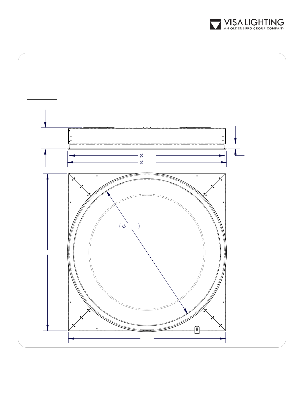
SHEETROCK INSTALLATION:
Provide a framed opening for centering the fixture. The LED housing opening should measure
1.
between 44-1/2" and 48" square. This will help support the fixture when it is fully installed.
Remove lens and trim frame. Re-attach the trim frame screws to the LED housing for use
2.
later. The lens and trim frame are not re-installed until all sheetrock work is completed.
Remove driver/wiring cover.
3.
Secure the fixture to the structure above using threaded rod and nuts into the (4)
.281 holes
4.
provided (see page 2). Make sure to locate the fixture so the bottom of the square housing is
1-3/8" (+0.00"/-0.125") above the bottom of the finished surface.
NOTE:
Adjustment to the
fixture height is done by raising or lowering the fixture using the threaded rods. Do not fully
tighten the fixture yet.
Make all the electrical connections required and following local codes that apply.
5.
Re-attach driver/wiring cover.
6.
Complete sheetrock installation.
NOTE:
Protect LEDs during sheetrock installation and
7.
finishing.
Once sheetrock is completed, cut circular opening for trim frame.
NOTE:
Opening diameter to
8.
be 43.75" to 44.25".
Remove trim frame screws and re-attach the trim frame to the housing.
NOTE:
If the trim
9.
frame is not flush with sheet rock, raise or lower fixture at the threaded rod.
Re-attach the lens assembly.
10.
Drawing:
762262XX
Rev:
A
Sheet:
3 of 6
Eng:
CG2
Date Drawn:
1/11/17
INSTALLATION INSTRUCTIONS
Model:
CM1970-W, CM1972-W, CM1972-T
Fixture Family:
SYMMETRY
1717 West Civic Drive Milwaukee, WI 53209
414-354-6600
Design Modification Rights Reserved
© Visa Lighting 2016
!
When using electrical equipment, basic safety precautions should always be followed, including the following:
Read all instructions carefully before installing and save for future use.
•
Make sure all connections are in accordance with the National Electrical Code and local regulations.
•
To avoid possible electric shock, be sure the power supply is turned off before servicing or installing the fixture
•
Service should be performed by qualified personnel.
•
These instructions may not cover all details or variations. If additional information is needed, please contact Visa Lighting.
•
Document Description: Installation Instructions for
Symmetry Series Luminaires

FIXTURE SUPPORT WIRES
(by others)
LOCATIONS FOR SUPPORT WIRE
T-BAR SCREWS (2)
T-BAR BRACKET
T-BAR GRID INSTALLATION:
Attach the T-bar brackets to each of the (4) corners using
1.
the provided screws.
Install the fixture in the T-bar grid system by lifting the
2.
fixture through the opening and lowering it onto the T-bar
grid.
Adjust the corner brackets so the bottom of the round trim
3.
ring is at the same height as the bottom of the T-Bars.
Support the fixture with wires attached to the building
4.
structure on all (4) corners.
Drawing:
762262XX
Rev:
A
Sheet:
4 of 6
Eng:
CG2
Date Drawn:
1/11/17
INSTALLATION INSTRUCTIONS
Model:
CM1970-W, CM1972-W, CM1972-T
Fixture Family:
SYMMETRY
1717 West Civic Drive Milwaukee, WI 53209
414-354-6600
Design Modification Rights Reserved
© Visa Lighting
!
When using electrical equipment, basic safety precautions should always be followed, including the following:
Read all instructions carefully before installing and save for future use.
•
Make sure all connections are in accordance with the National Electrical Code and local regulations.
•
To avoid possible electric shock, be sure the power supply is turned off before servicing or installing the fixture
•
Service should be performed by qualified personnel.
•
These instructions may not cover all details or variations. If additional information is needed, please contact Visa Lighting.
•
Document Description: Installation Instructions for
Symmetry Series Luminaires

1.375
5.94
44.53
43.64
44.00
44.00
41.28
Wiring Instructions - Over Bed Units
All AC inputs to fixture must be supplied from the same branch circuit.
1.
AMBIENT LINE and EXAM LINE must both be energized to achieve EXAM light levels
2.
on patient bed surface.
Dimensions:
Drawing:
762262XX
Rev:
A
Sheet:
5 of 6
Eng:
CG2
Date Drawn:
1/11/17
INSTALLATION INSTRUCTIONS
Model:
CM1970-W, CM1972-W, CM1972-T
Fixture Family:
SYMMETRY
1717 West Civic Drive Milwaukee, WI 53209
414-354-6600
Design Modification Rights Reserved
© Visa Lighting
!
When using electrical equipment, basic safety precautions should always be followed, including the following:
Read all instructions carefully before installing and save for future use.
•
Make sure all connections are in accordance with the National Electrical Code and local regulations.
•
To avoid possible electric shock, be sure the power supply is turned off before servicing or installing the fixture
•
Service should be performed by qualified personnel.
•
These instructions may not cover all details or variations. If additional information is needed, please contact Visa Lighting.
•
Document Description: Installation Instructions for
Symmetry Series Luminaires

CM1972-T - TUNABLE WHITE
Technical Information:
Each Symmetry Tunable White unit is built using two Lumenetix Araya LED kits. Fixtures are
to be commissioned using the
Araya Tunable Color iOS APP
found in the App Store. When
commissioning, combine the two kits into one group for best performance.
DMX Color Output Guide:
CCT
CRI
R9
Delivered
Lumens
Power
(Watts)
DMX Value
1650 91 82 3600 68 0
2700 93 99 7200 110 44
3000 91 94 8400 128 57
3500 90 91 10300 156 79
4000 90 93 10300 158 101
5000 90 77 10400 158 138
6500 90 76 10100 159 195
8000 89 70 8500 135 255
Drawing:
762262XX
Rev:
A
Sheet:
6 of 6
Eng:
CG2
Date Drawn:
1/11/17
INSTALLATION INSTRUCTIONS
Model:
CM1970-W, CM1972-W, CM1972-T
Fixture Family:
SYMMETRY
1717 West Civic Drive Milwaukee, WI 53209
414-354-6600
Design Modification Rights Reserved
© Visa Lighting
!
When using electrical equipment, basic safety precautions should always be followed, including the following:
Read all instructions carefully before installing and save for future use.
•
Make sure all connections are in accordance with the National Electrical Code and local regulations.
•
To avoid possible electric shock, be sure the power supply is turned off before servicing or installing the fixture
•
Service should be performed by qualified personnel.
•
These instructions may not cover all details or variations. If additional information is needed, please contact Visa Lighting.
•
Document Description: Installation Instructions for
Symmetry Series Luminaires
This manual suits for next models
3
Table of contents
Other Visa Lighting Lighting Equipment manuals
Popular Lighting Equipment manuals by other brands

Pentair Pool Products
Pentair Pool Products IntellipH Installation and user guide

Balmani
Balmani Livigno User information

IOTA
IOTA ILBLP CP12 HE SD LC CW instruction manual

Chauvet
Chauvet CH-PAR38PACK user guide

Larson Electronics
Larson Electronics EPL-120-150-EPP instruction manual

Chors
Chors Maman R TRC Assembly instructions