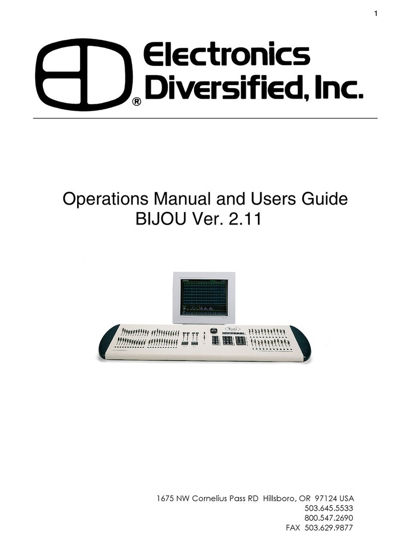
Electronics Diversified SMART User manual

SMART System
User Manual
Electronics Diversified, Inc..
Revision2.0,January2003
©2003ElectronicsDiversified, Inc.

SMART System
TABLE OF CONTENTS
OVERVIEW
Master Station buttons.........
Connections.........................
Power Consumption..............
PRESETS
Overview.............................
Activation............................
Editing................................
Global Presets.....................
XGlobal Presets...................
STATIONS
Overview.............................
SlaveLCD............................
10 Button.............................
2 Button...............................
Digital Slider........................
Remote Device Interface.......
IR Remote Station................
PATCH
Overview.............................
Patch Screen.......................
Non-Dimming.......................
COMBINES
Overview.............................
Activation............................
OverlappingCombines..........
Combine Setup....................
How: Preset vs. Zone............
XGlobals..............................
Patch Page switching............
LOCKOUTS
Overview.............................
Setup Lockout Actions.........
Assign Lockout Actions.........
Lockout Override..................
Example1:0ne preset lock.....
Example2:Left-side preset..
lock, right-side preset unlock
TIMECLOCK
Overview............................
Setup Clock........................
Setup Events......................
Turn On/Off Events..............
CONFIG SETTINGS
Remote Edit........................
Password............................
Master Room Assignment....
Activate Patch....................
Blackout.............................
PASSWORD
Changing Passwords...........
CLEARINGTHE SYSTEM
Clearing and Setup............
STATIONWIRING
Cabling...............................
HARDWARE PIECES
Overview............................
Removal of faceplate...........
1
2
3
3
4
4
4
6
8
9
9
12
13
14
18
20
22
22
23
24
24
24
25
26
27
28
29
29
30
30
31
33
37
37
38
39
40
40
40
41
41
42
43
44
45
45

OVERVIEW
SMART System
2
MASTER STATION BUTTONS
11
3
4
2
MappedButtons:
Illuminating Buttons mapped to the display.Any
button press results in the execution of the feature
mappedtothe button.
Up/DownButtons:
Allowsusertocontrolhighlightedfeaturedisplayed
by the Mapped Buttons. Mapped buttons are ued to
adjust levels, set time or curse through character
fieldsdependingonthiersetfunction.Character
fields will go SPACE, ! ,” , #, $, %, &, ’, (, ), *, +, ,,
-, ., 0 through 9, :, ;, <, =, >, ?, @, A through Z, [,
], ^, _, ’, a through z.
Menu Button:
Gives access between the preset menu page and
a menu of 8 other selections: ClearSys, Stations,
DimPatch, Combines, Lockouts,Timers, Pass-
word,andConfig.
EditButton:
When in the Preset activation page this button will
allow the user to toggle between the 3 sets of
preset pages.Within one of the Menu pages, it will
allow the user to cycle through pages of one of the
other topics:ClearSys, Stations,Dim Patch,
Combines, Lockouts,Timers, Password, and
Configurations.
1.
2.
3.
4.

2
1
3
POWER CONSUMPTION
OperatingVoltage:9-24V
For small (1-8 Stations) systems 15VDC is
sufficient. Larger systems (9-16 Stations) must
use a 24VDC Power Supply.
MasterStation
LCDSlave
Station
2/10/IR Stations
Slider Stations
RDI
110mA
50mA
60mA
100mA*
100mA
Current(12VDC)
CONNECTORS
SMART System
1.
2.
3.
Combines:
PIN1-8:CombineInputs
PIN10: Ground
DMXOutput:
PIN1: Ground
PIN2:Data-
PIN 3: Data+
Power/Serial Connection:
PIN1: Ground
PIN 2: Serial +
PIN 3: Serial -
PIN 4:+9 to 24VDC
OVERVIEW
3
*Ratingbasedupon10channel
slider.Lesserchannel models will
have a smaller maximum value.

The SMART System has 117 presets
total. Each of the 8 rooms have 13 user
editable presets, plus 13 XGlobal
Presets.The user has access to 7
presets at one time from the Preset
Menu.To access the other six presets,
press the More button.The 13th preset,
labeled OFF will be accessable in both
screens.
To Edit Presets,
Press Edit.
Select Room:
Press Rm.
Use Up/Down buttons to
select room.
Select Preset:
Press Pr.
Use Up/Down buttons to
select preset.
Select Zone to be edited:
Press Zn.
Use Up/Down buttons to
select zone.
Adjust Level:
Press Lv.
Use Up/Down buttons to
adjust level or use
Full,Off,+10 (increase by
10%) or -10% (decrease
by 10%).
SMART System
PRESETS
OVERVIEW
EDITING LEVELS/TIMES
4
PR1
PR2
PR3
Off
PR4
PR5
PR6
More
PR4
PR5
PR6
More
PR1
PR2
PR3
Off
Rm1
Pr1
Zn1
Lv100%
Full
+10
-10
Off
Rm1
Pr1
Zn1
Lv100%
Full
+10
-10
Off
Rm1
Pr1
Zn1
Lv100%
Full
+10
-10
Off
Rm1
Pr1
Zn1
Lv100%
Full
+10
-10
Off

SMART System
PRESETS
Set Fade Time:
Press Edit.
SelectTm.
Use Up/Down buttons to
increment by seconds,
Min-/Min+ to increment
by minutes and -10/+10
to increment by 10
second intervals.
Name Preset:
Press Edit.
Select Name.
Use Up/Down buttons to
select character. Character
fields will go SPACE, ! ,”
, #, $, %, &, ’, (, ), *, +, ,, -,
., 0 through 9, :, ;, <, =, >,
?, @, A through Z, [, ], ^, _,
’, a through z. Use !, 0, a,
and Ato quickly jump to
characters.
Return to Preset Menu:
Press Menu.
Note: All changes are being
recorded while the user is editing.
5
+Min
+10
-10
-Min
Rm1
Pr1
Tm00:05
Globalno
!
0
a
A
Rm1
Pr1
Name PR1
Lockout None

SMART System
PRESETS GLOBAL PRESETS
Normal presets allow levels to be adjusted
within a room and that room only.Global
presets allow the user to adjust different
zones in different rooms. Users can inhibit or
“skip” zones so that they will not be affected
by the preset. A global preset is most useful in
cases where lights in distant rooms need to be
turnedonsimultaneouslyorwhereaspecial
preset is needed for system wide control.
From Preset Menu,
To create a global,
press Edit.
Select Room:
Press Rm.
Use Up/Down buttons to
select room for the preset.
Select Preset:
Press Pr.
Use Up/Down buttons to
select preset.
Activate Global Function for this
Preset:Press Edit.
Press Global.
Press Up button. The display
should change from Global no to
Global yes.
Select Room:
Press Edit twice. The display
should show Global below Rm
and Pr in the left hand part of the
screen.
Press Edit again.*GLOBAL*
should display at the top.
Press Rm.
Use Up/Down buttons to select
room.
6
PR4
PR5
PR6
More
PR1
PR2
PR3
Off
Rm1
Pr1
Zn1
Lv100%
Full
+10
-10
Off
Rm1
Pr1
Zn1
Lv100%
Full
+10
-10
Off
Full
+10
-10
Off
Rm1
Pr1
*Global*
Full
+10
-10
Off
Rm1 *GLOBAL*
Zn1 *Rm1*
Lv100% *Pr1*
Skip yes
+Min
+10
-10
-Min
Rm1
Pr1
Tm00:05
Globalno

SMART System
PRESETS
Select Zone to be edited:
Press Zn.
Use Up/Down buttons to
select zone.
Adjust Level:
Press Lv.
Use Up/Down buttons to
adjust level or use Full,Off,+10
(increase by 10%) or -10%
(decrement by 10%).
Unskip Zone:
Press Skip.
Press Down button. Skip yes
should change to Skip no. A
zone that is left on Skip yes will
not be affected by this preset.
Set FadeTime:
Press Edit.
SelectTm.
Use Up/Down buttons incre-
ment by seconds, Min-/Min+
increment by minutes and -10/
+10 to increment by 10 second
intervals.
Name Preset:
Press Edit.
Select Name.
Use Up/Down buttons to select
character. Character fields will go
SPACE, ! ,” , #, $, %, &, ’, (, ), *,
+, ,, -, ., 0 through 9, :, ;, <, =,
>, ?, @, A through Z, [, ], ^, _,
’, a through z. Use !, 0, a,
and Ato quickly jump to
characters.
Return to Preset Menu:
Press Menu.
7
+Min
+10
-10
-Min
Rm1
Pr1
Tm00:05
Globalno
Full
+10
-10
Off
Rm1 *GLOBAL*
Zn1 *Rm1*
Lv100% *Pr1*
Skip yes
Full
+10
-10
Off
Rm1 *GLOBAL*
Zn1 *Rm1*
Lv100% *Pr1*
Skip yes
Full
+10
-10
Off
Rm1 *GLOBAL*
Zn1 *Rm1*
Lv100% *Pr1*
Skip yes
!
0
a
A
Rm1
Pr1
Name PR1
Lockout None

SMART System
PRESETS
XGLOBAL PRESETS
8
13 XGlobal Presets can replace presets in
combined rooms.The presets are not associated
with any room, thus dsignated on the master
station as X. Because they are a global preset,
they will affect only those zones in rooms that
are not“skipped”.They can only be activated with
a combine function and only be activated from
stationswithinthecombinedroom.
To assign an XGlobal Preset to a Combine
function, turn to page 25.
From Preset Menu,
To create an XGlobal,
press Edit.
Select Room:
Press Rm.
Use Up button to select room
X.The display should show
Global below Rm and Pr in the
left hand part of the screen
Press Edit.
Select Roomto Edit:
Press Edit again.*GLOBAL*
should display at the top.
Press Rm.
Use Up/Down buttons to select
room.
Follow the directions on page 7 for
editing Global presets.
Full
+10
-10
Off
RmX
Pr1
*Global*
PR4
PR5
PR6
More
PR1
PR2
PR3
Off
Rm1
Pr1
Zn1
Lv100%
Full
+10
-10
Off
Full
+10
-10
Off
Rm1 *GLOBAL*
Zn1 *RmX*
Lv0% *Pr1*
Skip yes

SMART System
STATIONS
9
OVERVIEW
The SMART System can handle up to 16 stations:
6 types of stations are available on the SMART System: LCD
Slave, 10 Button, 2 Button, Digital Slider, IR Remote, and Remote
DeviceInterface.
Stations can be spread out over 1000 feet of Alpha 1133.
The SMART System can only address one station and cannot
allow“mirroring”of stations.
The Master Station itself can be used as a station and is non
addressable.
To read how to select the room the Master station will operate
turn to page 31.
SLAVE LCD STATION
MappedButtons:
Illuminating Buttons mapped to the display.
Any button press results in the execution of
the feature mapped to the button.
Up/Down Buttons:
Allowsusertocontrolhighlightedfeature
displayed by the Mapped Buttons. Used to
adjust levels or set time.
Menu Button:
Returnstothepreset menu page.
EditButton:
Prompts for the next page within the Preset
editpages
1.
2.
3.
4.
11
3
4
2

SMART System
STATIONS
10
Adjust Level:
Press Lv.
Use Up/Down buttons to
adjust level or use
Full,Off,+10 (increase by
10%) or -10% (decrease by
10%).
Set Fade Time:
Press Edit.
SelectTm.
Use Up/Down buttons to
increment by seconds,
Min-/Min+ to increment
by minutes and -10/+10
to increment by 10
second intervals.
Return to Preset Menu:
Press Menu.
To Edit Presets,
Press Edit.
Select Preset:
Press Pr.
Use Up/Down buttons to
select preset.
Select Zone to be edited:
Press Zn.
Use Up/Down buttons to
select zone.
PR4
PR5
PR6
More
PR1
PR2
PR3
Off
Rm1
Pr1
Zn1
Lv100%
Full
+10
-10
Off
Rm1
Pr1
Zn1
Lv100%
Full
+10
-10
Off
Rm1
Pr1
Zn1
Lv100%
Full
+10
-10
Off
+Min
+10
-10
-Min
Rm1
Pr1
Tm00:05
Globalno

SETUP LCD:
From Preset Menu,
On the Master Station,
Press Menu. Main Menu displays.
Press Stations.
Press Station 0.
Use Up/Down arrows to select a
Station. In the station name, LCD
refers to a Slave LCD Station.
Select Room:
Press Room.
Use Up/Down buttons to assign a
room to a station.
Select Backlight:
Press BL.
Use Up/Down button to select
between backlight constant on,
constant off, or instant on/ delay
off.
Test the Station:
Press Test.
Station will flash LEDs
Press any other button to resume
normal functions.
SMART System
STATIONS
11
Return to Preset Menu:
Press Menu.
Station0
Room1
Test
Station1 LCD
Room1
BL:delay Test
Lockouts
Timers
Password
Config
Clear Sys
Stations
DimPatch
Combines
Station1 LCD
Room1
BL:delay Test
Station1 LCD
Room1
BL:delay Test

SMART System
STATIONS
12
10 BUTTON STATION
Presets 1-6 (7-12 when More is activated)
Press a button to execute a preset in a room
Master Room Level Buttons
Adjust levels up or down in all zones within a
room.
MoreButton
Switchesbetween Presets 1-6 and 7-12
OffButton
Press to Execute Preset 13 (Off)
1.
2.
3.
4
1
2
3
4SETUP 10 BUTTON:
From Preset Menu,
On the Master Station,
Press Menu. Main Menu displays
Press Stations.
Press Station 0.
Use Up/Down arrows to select a
Station. In the station name, 10Btn
refers to a 10 Button Station.
Select Room:
Press Room.
Use Up/Down buttons to assign a
room to a station.
Test the Station:
Press Test.
Station will flash LEDs
Press any other button to resume
normal functions.
Lockouts
Timers
Password
Config
Clear Sys
Stations
DimPatch
Combines
Station0
Room1
Test
Station1 10Btn
Room1
Test
Return to Preset Menu:
Press Menu.
Station1 10Btn
Room1
Test

SMART System
STATIONS
13
2 BUTTON STATION 1
2
OnButton
Press button to execute an assigned preset
(seebelow).
OffButton
Press button to execute preset 13 (Off)
1.
2.
SETUP 2 BUTTON:
From Preset Menu,
On the Master Station,
Press Menu. Main Menu Displays.
Press Stations.
Press Station 0.
Use Up/Down arrows to select a
Station. In the station name, 2Btn
refers to a 10 Button Station.
Select Room:
Press Room.
Use Up/Down buttons to assign a
room to a station.
Select On Preset:
Press On preset.
Use Up/Down buttons to assign a
preset on a button.
Test the Station:
Press Test.
Station will flash LEDs
Press any other button to resume
normal functions.
Station0
Room1
Test
Return to Preset Menu:
Press Menu.
Lockouts
Timers
Password
Config
Clear Sys
Stations
DimPatch
Combines
Station1 2Btn
Room1
Onpreset: 1 Test
Station1 2Btn
Room1
Onpreset: 1 Test
Station1 2Btn
Room1
Onpreset: 1 Test

SMART System
STATIONS
14
DIGITAL SLIDER STATION
1
2
34 56
7
8
9
1.
2.
3.
4.
5.
6.
7.
8.
9.
Presets 1-6 (7-12 when More is
activated)
Press a button to execute a preset in a
room.
RecordButton
Used in saving levels to a preset.Also,
this button is used for paging different
channels.(See recording presets and
changing zone pages on pages 15
and 16).
OffButton
Press to Execute Preset 13 (Off).
MoreButton
Toggles between Presets1-6and7-12.
Master/FadeRate Button
Toggles the M/R display (9) from
displaying master control use and the
fade rate of an executed preset. It will
also toggle the use of the M/R level
controls (6) from adjusting all zones
within a room to adjusting preset fade
rateswhen recording.
Master/Fade Rate Control
Press to raise or lower level in a room
or adjust fade rate as desired (See
recording presets about fade rate
changes on page 15).
Channel Level Controls
Press to raise or lower an individual
channellevelwithinaroom.
ChannelLevels
10-segment LEDS show intesity values
from 0 to 100% on each channel.
M/R Levels
10-segmentLEDsshowsmasterfader
action and fade rates up to 5 minutes.

SMART System
STATIONS
15
To Record a Preset:
Adjust Channel Level Con-
trols to desired levels.
Press and hold Record button.
Press Preset to be stored in.
Release both buttons.
View Fade Rate:
Press M/R button.
To Change Fade Rate of a Preset:
View Fade Rate.
Press and hold Record button.
Use M/R Control to raise or
lower fade rate.
Release Record when fin-
ished editing.This changes
the fade rate of the active
preset.
CHANGING ZONE PAGES:
Sliderstationshave programmable
zonal paging, allowing the user to edit
all or some of the zones within a room
reguardlessofsliderstationconfigura-
tion and zones within a room.The
user can view 4,6,8, or 10 zones at a
time(baseduponhowmanyslider
controlsthereare).The user can
advanceor“page” to another groupof
zones within the room.Thus on a 4
channel slider the user can view the
followingzones:1through4 on the
first page, 5 through 8 on the second
page,9through 12 on the third page,
and 13 through 16 on the fourth.

SMART System
STATIONS
16
To Change Zone Page,
Press Record button and Down
Zone button on the page to be
viewed (Ex.First Page would be the
first Down Zone button).The lowest
LED over the slider button will
flash.
Note:The LED for the first page will
not flash.
SETUP SLIDER STATION:
From Preset Menu,
On the Master Station,
Press Menu. Main Menu displays.
Press Stations.
Press Station 0.
Use Up/Down arrows to select a
Station. In the station name, Sldr
refers to a Slider Station.
Select Room:
Press Room.
Use Up/Down buttons to assign a
room to a station.
Set Channel Size of Slider :
Press Channels.
Use Up/Down buttons to designate
the maximum number of zones that
can be displayed on that station.
Test the Station:
Press Test.
Station will flash LEDs
Press any other button to resume
normal functions.
Return to Preset Menu:
Press Menu.
Lockouts
Timers
Password
Config
Clear Sys
Stations
DimPatch
Combines
Station0
Room1
Test
Station1 Sldr
Room1
Channels: 1
Page:1 Test
Station1 2Btn
Room1
Channels: 1
Page:1 Test
Station1 2Btn
Room1
Channels: 1
Page:1 Test

SMART System
STATIONS
17
1
2
3
4
Power/Serial
Connection
PIN 1-12:input port latches
PIN 13: common for input port latches
PIN14:9-24VDCfrom LAN
PIN15:GroundfromLAN
PIN 1-12:output port latches
PIN 13:common for output port
latches
InputLEDs1-12:lamponwhen
latch is closed by
outsidesource
OutputLEDs1-12:lamponwhenRDIhas
closed the latch
1.
2.
3.
4.
REMOTE DEVICE INTERFACE
OVERVIEW
The Remote Device Interface (RDI) allows the
SMART System to communicate with other devices
throughmaintainormomentary switching.Each port
hasalatched(On)functionandunlatched(Off)
function, allowing the user to activate to separate
fuctions on one switch ( Example: Preset 1 for
Port1 On function and Preset Off for port 1 Off
function).This is useful for turning on and off
combines or a blackout switch for a room.
Momemtary switching can be used by setting the
On and Off functions to the same setting. (Example:
Preset 1 for Port 1 On and Off functions and Preset
Off for Port 2). A custom keypad for a master
controlpanel/swtichboardmayusemomentary
switching on the RDI to activate fuctions throughout
the SMART System.

SMART System
STATIONS
18
SEUP RDI FUNCTIONS:
From Preset Menu,
On the Master Station,
Press Menu. Main Menu displays.
Press Stations.
Press Station 0.
Use Up/Down arrows to select a
Station. In the station name, RDI
refers to the Remote Device Inter-
face.
Select a Port:
Press Port.
Use the Up/Down buttons to select
an input or output port latch (1-12).
Select a Room:
Press Room.
Use the Up/Down buttons to select
a room that RDI will activate or
sense.The same port can be used
for multiple rooms.
Select an On Function:
Press the 4th button down on the
left.When this button is lit, the user can
designate functions to the RDI
Press on
Use Up/Down buttons to select an
action for the given room when the input
port has been latched. The RDI
can: Blackout/ un-Blackout
Turn the timeclock operationson
or off execute
Presets1-13
Combine or UnCombine
1-8.
Lockouts
Timers
Password
Config
Clear Sys
Stations
DimPatch
Combines
Station0
Room1
Test
Station1 RDI
Port1
Room1
On:none
on
off
out
pol
Station1 RDI
Port1
Room1
On:none
on
off
out
pol
Station1 RDI
Port1
Room1
On:none
on
off
out
pol

Select an Off Function :
Press off
Use Up/Down buttons to select an
action for the given room when the input
port is open. The RDI can:
Blackout/ un-Blackout
Turn the timeclock operationson
or off execute
Presets1-13
Combine or UnCombine
1-8.
Select an Output Function:
Press out
Use Up/Down buttons to latch the
output port for a given executed preset
The RDI can respond to the following
actions:
Blackout/ un-Blackout,
Turn the timeclock operations on
or off,
Execution of Presets1-13,
Combine or UnCombine 1-8.
POLARITY:
This determines whether or not the Remote
Device Interface should keep an active high or
active low on a selected port.
Give the Polarity of the Port:
Press pol.
Press Up button for the RDI to pull up
high to latch or signal action.The
display will show Pol: high. Press
Down button for the RDI to pull down
low to latch or signal action.The display
will show Pol: low.
Return to Preset Screen:
Press Menu.
SMART System
19
Station1 RDI
Port1
Room1
On:none
on
off
out
pol
STATIONS
Station1 RDI
Port1
Room1
On:none
on
off
out
pol
Table of contents
Other Electronics Diversified Lighting Equipment manuals
Popular Lighting Equipment manuals by other brands
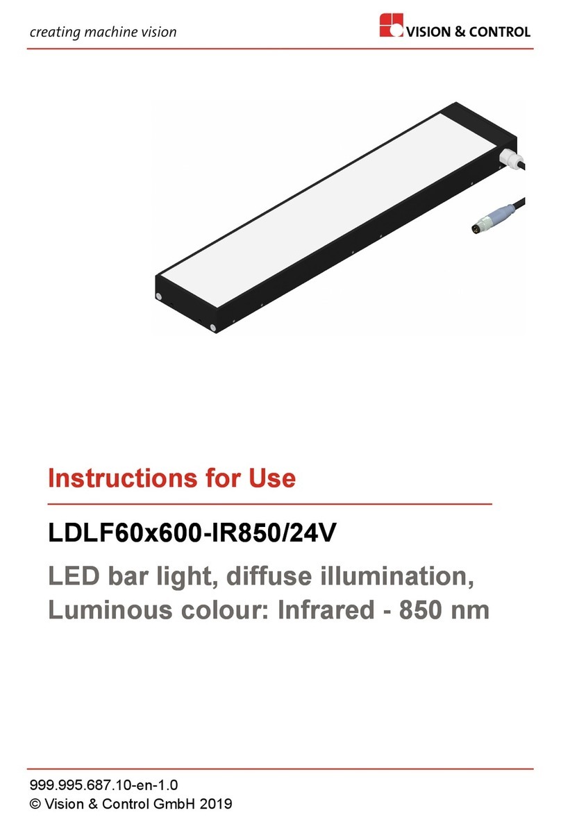
Vision & Control
Vision & Control LDLF60x600-IR850/24V Instructions for use
Luci
Luci RIMiT sm instruction manual

Westinghouse
Westinghouse LED T8 Tube Series owner's manual
RAB Lighting
RAB Lighting ND4R installation instructions
Elinchrom
Elinchrom D-Lite RX 2 Operation manual
Philips
Philips TrueLine SM530C manual
