Installation and Operating Guidelines
4
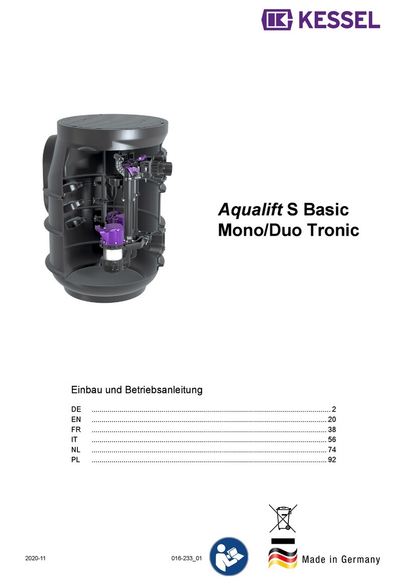
1. Select a suitable location for the pumping station. Where possible, installation of a pumping station
in a roadway should be avoided due to the need for periodic maintenance of the pumps contained
therein. If the location is adjacent to a roadway, the installation method should take account of the
imposed loads likely to be transmitted to the chamber by traffic etc.
2. Excavate the minimum opening in the ground to receive the chamber and external connections. It is
the installer’s responsibility to measure the chamber before sizing the excavation. If a machine is
used to remove the spoil, the sides of the excavation should be battened for stability. Where ground
water is present in the excavation you must make a provision for a sump in one corner for
dewatering purposes.
3. Where ground water is present in the excavation, de-watering must be undertaken throughout the
installation procedure and until the backfill has completely set.
4. Lift the chamber into the excavation (please refer to section 3, lifting guide) and position it such that
the inlet and outlet pipework connections are correctly aligned and temporarily pack the base to the
correct level. Mark all connections and remove the chamber before installing the rubber seals
(100mm pipe). Please note that all connections should be aligned square to the chamber enabling
the seals to remain watertight, connections: 100mm cable duct, 100mm vent duct, inlet pipework =
subject to inlet pipework size and pumping main (please use fittings supplied).
5. Simply lay clean hardcore to the base of the excavation ensuring that it is consolidated to a
minimum thickness of 150mm, then lay a WET mass concrete base to a thickness adequate for the
ground conditions (minimum 200mm), on top of the hardcore or to structural engineers
requirements.
6. Lift the chamber into the excavation (please refer to section 3, lifting guide) and carefully position it
onto the WET mass concrete base ensuring that no loose debris is inadvertently knocked onto the
base, under the chamber during this procedure. Position it such that the inlet and outlet pipework
are correctly aligned. The chamber is be imbedded 50mm into the WET mass concrete base,
provision should made to prevent the chamber from being lowered more than 50mm into the
concrete.
7. Once the chamber is positioned connect the 100mm cable duct, 100mm vent duct and inlet
pipework to the chamber (please use fittings supplied). The discharge pipework can then be
connected. We recommend that all discharge pipework be black MDPE or HDPE pipe.
8. The vent duct should be vented to atmosphere at high level. An air admittance valve/durgo/one way
valve must NOT be used.
9. The chamber MUST be ballasted with water at the same rate as backfilling such that the level
difference between the water and backfill does not exceed 300mm at any time.
10. Whilst the concrete base is still WET pour a WET mass concrete surround to a thickness adequate
for the ground conditions (minimum 250mm) upto the top of the chamber in a single pour. The
concrete must be evenly poured around the chamber ensuring that no voids are left within the
concrete. Care must be taken to ensure that any pipes (or other connections) made, are not
damaged. During the concrete pour, ensure that the chamber is vertical (by use of a spirit level
across the chamber’s opening). Additionally, ensure that the chamber is at the correct depth level.
DO NOT REMOVE THE WATER FROM THE CHAMBER.


