PR Elecronics 5333 User manual

5333
CCOE
2-Wire Programmable
Transmitter
No. 5333V113-UK
From ser. no.:
132094001 - 132094630
141115001

1707
Revision Notes
The following list provides notes concerning revisions of this document.
Rev. ID Date Notes
111 13/45 IECEx and INMETRO approvals added
112 15/14 PESO/CCOE approval added
GOST approval replaced with
EAC approval
113 17/07 FM installation drawing updated
INMETRO installation drawings updated

5333V113-UK 1
2-WIRE
PROGRAMMABLE TRANSMITTER
5333
Contents
Application................................................................................................. 2
Technical characteristics...................................................................... 2
Mounting / installation ......................................................................... 2
Applications............................................................................................... 3
Order: 5333............................................................................................... 4
Electrical specifications........................................................................ 4
Connections .............................................................................................. 7
Block diagram........................................................................................... 8
Programming ............................................................................................ 9
Mechanical specifications ................................................................... 10
Mounting of sensor wires ................................................................... 10
Appendix .................................................................................................... 11
ATEX Installation Drawing - 5333A ............................................ 12
ATEX Installation Drawing - 5333D ............................................ 13
IECEx Installation Drawing - 5333A............................................ 15
IECEx Installation Drawing - 5333D............................................ 16
FM Installation Drawing - 5333D................................................. 18
CSA Installation Drawing - 5333D............................................... 20
INMETRO Instruções de Segurança - 5333A........................... 21
INMETRO Instruções de Segurança - 5333D........................... 22

2 5333V113-UK
2-WIRE PROGRAMMABLE TRANSMITTER
5333
• RTD or Ohm input
• High measurement accuracy
• 3-wire connection
• Programmable sensor error value
• For DIN form B sensor head mounting
Application
• Linearised temperature measurement with Pt100...Pt1000 or Ni100...Ni1000
sensor.
• Conversion of linear resistance variation to a standard analogue current
signal, for instance from valves or Ohmic level sensors.
Technical characteristics
• Within a few seconds the user can program PR5333 to measure temperatures
within all RTD ranges defined by the norms.
• The RTD and resistance inputs have cable compensation for 3-wire
connection.
Mounting / installation
• For DIN form B sensor head mounting. In non-hazardous areas the 5333 can be
mounted on a DIN rail with a special fitting.

5333V113-UK 3
APPLICATIONS
V+
mA
+-
V+
mA
+-
RTD to 4...20 mA
2-wire installation
in control room
Resistance to 4...20 mA
2-wire installation
in control room

4 5333V113-UK
Electrical specifications
Specifications range:
-40°C to +85°C
Common specifications:
Supply voltage, DC
Standard.................................................................. 8...35 V
CSA, FM, ATEX, IECEx & INMETRO................ 8...30 V
Internal power dissipation
Standard.................................................................. 25 mW...0.8 W
CSA, FM, ATEX, IECEx & INMETRO................ 25 mW...0.7 W
Voltage drop .............................................................. 8 VDC
Warm-up time............................................................ 5 min.
Communications interface ................................... Loop Link
Signal / noise ratio .................................................. Min. 60 dB
Response time (programmable)......................... 0.33...60 s
Signal dynamics, input........................................... 19 bit
Signal dynamics, output ....................................... 16 bit
Calibration temperature ........................................ 20...28°C
Order: 5333
Type Version
5333 Standard : A
CSA, FM, ATEX, IECEx & INMETRO : D
5333V113-UK 5
General values
Input type
Absolute
accuracy
Temperature
coefficient
All ≤±0.1% of span ≤ ±0.01% of span / °C
Basic values
Input type
Basic
accuracy
Temperature
coefficient
RTD ≤±0.3°C ≤±0.01°C/°C
Lin. R ≤±0.2 Ω ≤ ±20 mΩ/ °C
EMC immunity influence........................................... < ±0.5% of span
Accuracy, the greater of general and basic values:
Effect of supply voltage variation.................... ≤0,005% of span / VDC
Vibration...................................................................... IEC 60068-2-6 : 2007
2...25 Hz.................................................................. ±1.6 mm
25...100 Hz ...................................................... ±4 g
Max. wire size............................................................ 1 x 1.5 mm2stranded wire
Humidity...................................................................... < 95% RH (non-cond.)
Dimensions................................................................. Ø 44 x 20.2 mm
Protection degree (enclosure / terminal)....... IP68 / IP00
Weight .......................................................................... 50 g
Electrical specifications, input:
RTD and linear resistance input:
Max. offset ................................................................. 50% of selec. max. value
Cable resistance per wire (max.) ....................... 10 Ω
Sensor current........................................................... > 0.2 mA, < 0.4 mA
Effect of sensor cable resistance
(3-wire) ........................................................................ < 0.002 Ω / Ω
Sensor error detection........................................... Yes
RTD
type
Min.
value
Max.
value
Min.
span
Standard
Pt100
Ni100
Lin. R
-200°C
-60°C
0 Ω
+850°C
+250°C
10000 Ω
25°C
25°C
30 Ω
IEC 60751
DIN 43760
-----

6 5333V113-UK
Output:
Current output:
Signal range ............................................................... 4...20 mA
Min. signal range...................................................... 16 mA
Updating time ........................................................... 135 ms
Load resistance......................................................... ≤(Vsupply- 8) / 0.023 [Ω]
Load stability............................................................. < ±0.01% of span / 100 Ω
Sensor error detection:
Programmable ........................................................... 3.5...23 mA
NAMUR NE43 Upscale........................................... 23 mA
NAMUR NE43 Downscale..................................... 3.5 mA
Of span = Of the presently selected range
Approvals:
EMC................................................................................ 2014/30/EU
CCOE .............................................................................. P337392/3
RoHS ............................................................................. 2011/65/EU
EAC................................................................................. TR-CU 020/2011
Marine approval:
DNV-GL, Ships & Offshore.................................... Standard for Certification No. 2.4
Ex / I.S.:
ATEX 2014/34/EU
5333A...................................................................... KEMA 10ATEX0003 X
5333D...................................................................... KEMA 03ATEX1535 X
FM certificate ............................................................ FM17US0013X
CSA certificate .......................................................... 1125003
IECEx............................................................................. DEK 13.0036 X
INMETRO ..................................................................... DEKRA 16.0014 X
CCOE .............................................................................. P337392/4
EAC Ex TR-CU 012/2011 ..................................... RU C-DK.GB08.V.00410

5333V113-UK 7
CONNECTIONS
1 2
mA -
+
3463 46 3 463 46
Output:
2-wire installation
Input:
RTD, 2-wire RTD, 3-wire Resistance, 2-wire Resistance, 3-wire
8 5333V113-UK
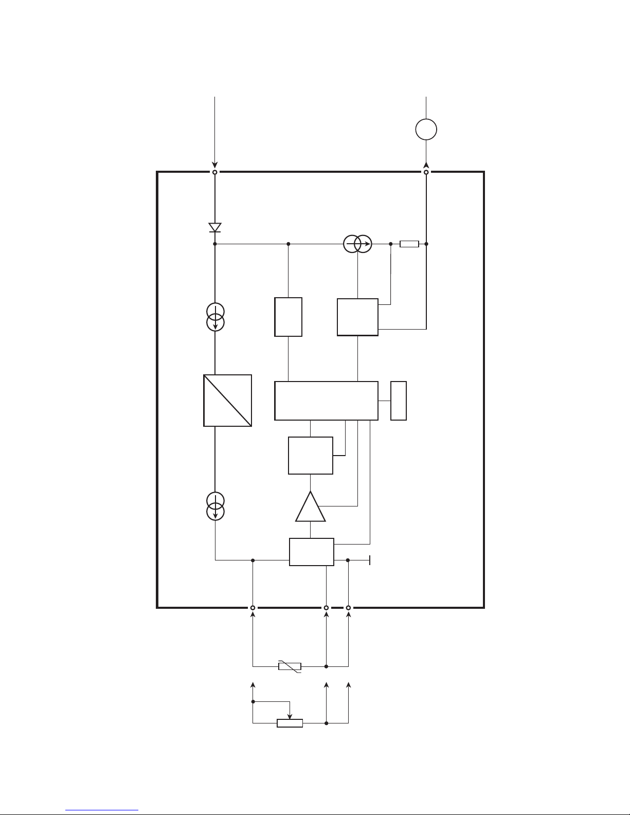
BLOCK DIAGRAM
0...16
mA
1
3
6
2mA
M UX
4 mA
5333
PGA
D /A
A /D
C PU
EEPRO M
DC
DC
4
Supply -
4...20 mA
Input +
Input -
Supply +
8...35 VDC
Comp. +
RTD
Lin.R
Comm.
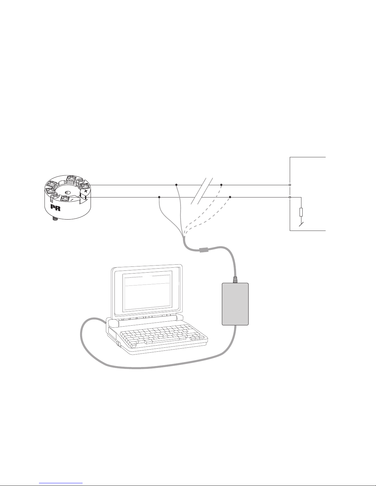
5333V113-UK 9
• Loop Link is a communications interface that is needed for programming 5333.
• For programming please refer to the drawing below and the help functions in
PReset.
• Loop Link is not approved for communication with modules installed in
hazardous (Ex) areas.
Order: Loop Link
PROGRAMMING
1
2
*
*
Loop
Link 5909 - USB
FileProductInputOutputCommunication LanguageOption08:30:00
PRetop5331
Date:2004-8-10
043201594
PRelectronics
AnaloginputAnalogoutput
Serial no:
Inputtype:Outputtype:4-20mA
Upscale
Sensorerror:
Pt100DIN/IEC
0.00-50.00C
3-wire
1.00sec
------
Inputrange:
Connection:
Coldjunctioncomp:
Response time:
T
ag no:
5333
Receiving
Equipment
Disconnect
+Vsupply
Black
Red Yellow
Green
Input
* Connected only for
"on-line" programming
Connector

20.2m m
+-
+-
ø 6 mm
33 mm
ø 44 mm
10 5333V113-UK
Mechanical specifications Mounting of sensor wires
Wires must be mounted between the metal
plates.

APPENDIX
ATEX Installation Drawing - 5333A
ATEX Installation Drawing - 5333D
IECEx installation drawing - 5333A
IECEx installation drawing - 5333D
FM Installation Drawing - 5333D
CSA Installation Drawing - 5333D
INMETRO Instruções de Segurança - 5333A
INMETRO Instruções de Segurança - 5333D
5333V113-UK 11

12 5333V113-UK
5333QA02
LERBAKKEN 10, 8410 RØNDE DENMARK. WWW.PRELECTRONICS.COM
Revision date:
2013-08-07
Version Revision
V2R0
Page:
1/1
ATEX Installation drawing
For safe installation of 5333A the following must be observed. The module shall only be installed
by qualified personnel who are familiar with the national and international laws, directives and
standards that apply to this area.
Year of manufacture can be taken from the first two digits in the serial number.
.
ATEX Certificate KEMA 10ATEX 0003X
Marking
Standards EN 60079-0 : 2012, EN 60079-11 : 2012, EN 60079-15 : 2010
Special conditions for safe use
For type of protection Ex nA, the transmitter shall be mounted in a metal enclosure providing a
degree of protection of at least IP54 according to EN60529.
For use in the presence of combustible dusts the transmitter shall be mounted in an enclosure
providing a degree of protection of at least IP6X in accordance with EN60529, the surface
temperature of the outer enclosure is 20 K above the ambient temperature
For an ambient temperature ≥60ºC, heat resistant cables shall be used with a rating of at least
20 K above the ambient temperature.
T4: -40 ≤Ta ≤85ºC
T6: -40 ≤Ta ≤60ºC
II 3 G Ex nA [ic] IIC T4 … T6 Gc
II 3 G Ex ic IIC T4…T6 Gc
II 3 D Ex ic IIIC Dc
Terminal: 3,4,6
Ex nA [ic]
Uo: 5V
Io: 4.0 mA
Po: 20 mW
Lo: 900 mH
Co: 1000 μF
Terminal: 1,2
Ex nA
Umax. ≤35 VDC
Terminal: 1,2
Ex ic
Ui = 35 VDC
Ii = 110mA
Li = 10 μH
Ci = 1.0 nF
5333V113-UK 13
5333QA01
LERBAKKEN 10, 8410 RØNDE DENMARK. WWW.PRELECTRONICS.COM
Revision date:
2013-08-07
Version Revision
V2R0
Page:
1/2
ATEX Installation drawing
For safe installation of 5333D the following must be observed. The module shall only be installed by
qualified personnel who are familiar with the national and international laws, directives and
standards that apply to this area.
Year of manufacture can be taken from the first two digits in the serial number.
ATEX Certificate KEMA 03ATEX 1535 X
Marking
Standards EN 60079-0 : 2012, EN 60079-11 : 2012, EN 60079-26 : 2007,
EN 60079-15 : 2010
Non Hazardous Area
Hazardous area
Zone 0, 1, 2, 20, 21, 22
II 1 G Ex ia IIC T4...T6 Ga
II 1 D Ex ia IIIC Da
II 1 M Ex ia I Ma
Terminal: 3,4,6
Uo: 27 VDC
Io: 7 mA
Po: 45 mW
Lo: 35 mH
Co: 90 nF
Terminal: 1,2
Ui: 30 VDC
Ii: 120 mA
Pi: 0.84 W
Li: 10μH
Ci: 1.0nF
1
2
6
5
4
3
+
-
Barrier
5333D
T4: -40 ≤Ta ≤85ºC
T6: -40 ≤Ta ≤60ºC

14 5333V113-UK
5333QA01
LERBAKKEN 10, 8410 RØNDE DENMARK. WWW.PRELECTRONICS.COM
Revision date:
2013-08-07
Version Revision
V2R0
Page:
2/2
Installation notes:
In a potentially explosive gas atmosphere, the transmitter shall be mounted in an enclosure in
order to provide a degree of protection of at least IP20 according to EN60529.
If the transmitter is installed in an explosive atmosphere requiring the use of equipment of
category 1 G, 1 M or 2 M, and if the enclosure is made of aluminum, if must be installed such,
that ignition sources due to impact and friction sparks are excluded.
If the enclosure is made of non-metallic materials, electrostatic charging shall be avoided.
For installation in a potentially explosive dust atmosphere, the following instructions apply:
The transmitter shall be mounted in a metal enclosure form B that is providing a degree of
protection of at least IP6X according to EN60529, that is suitable for the application and
correctly installed.
Cable entries and blanking elements shall be used that are suitable for the application and
correctly installed.
For an ambient temperature ≥60ºC, heat resistant cables shall be used with a rating of at least
20 K above the ambient temperature.
The surface temperature of the enclosure is equal to the ambient temperature plus 20 K, for a
dust layer with a thickness up to 5 mm

5333QI02
LERBAKKEN 10, 8410 RØNDE DENMARK. WWW.PRELECTRONICS.COM
Revision date:
2013-06-03
Version Revision
V1R0
Page:
1/1
IECEx Installation drawing
For safe installation of 5333A or 5343A the following must be observed. The module shall only be
installed by qualified personnel who are familiar with the national and international laws,
directives and standards that apply to this area.
Year of manufacture can be taken from the first two digits in the serial number.
Certificate IECEx DEK 13.0036X
Marking
Standards IEC 60079-0 : 2011, IEC 60079-11 : 2011, IEC 60079-15 : 2010
Terminal Ex nA [ic] Ex ic
1,2 Umax = 35V Ui : 35V, Ii:110mA, Ii:10µH, Ci:1,0nF
3,4,6 Uo: 5V, Io: 4mA, Po: 20mW, Lo: 900mH, Co: 1000µF
Installation note:
For installation in a potentialy explosive gas atmosphere, the following instructions apply:
For nA installation the transmitter must be installed in an metal enclosure e.g. a form B
enclosure, providing a degree of protection of at least IP54 according to IEC60529 or in an
enclosure with type of protection Ex n or Ex e.
For ic installation the transmitter must be installed in enclosure providing a degree of
protection of at least IP20 according to IEC60529 and that is suitable for the application.
Cable entry devices and blanking elements shall fulfill the same requirements
For an ambient temperature ≥60ºC, heat resistant cables shall be used with a rating of at
least 20 K above the ambient temperature.
For installation in a potentially explosive dust atmposphere, the following instructions apply:
The surface temperature of the enclosure is equal to the ambient temperature plus 20 K, for a
dust layer with a thickness up to 5 mm.
The transmitter must be mounted in a enclosure according to DIN 43729 that provides a
degree of protection of at least IP6X according to IEC60529, and that is suitable for the
application. Cable entry devices and blanking elements shall fulfill the same requirements.
T4: -40 ≤Ta ≤85ºC
T6: -40 ≤Ta ≤60ºC
Ex nA [ic] IIC T6..T4 Gc
Ex ic IIC T6..T4 Gc
Ex ic IIIC Dc
5333V113-UK 15

5333QI01
LERBAKKEN 10, 8410 RØNDE DENMARK. WWW.PRELECTRONICS.COM
Revision date:
2013-06-03
Version Revision
V1R0
0Page:
1/2
IECEx Installation drawing
For safe installation of 5333D or 5343B the following must be observed. The module shall only be
installed by qualified personnel who are familiar with the national and international laws, directives
and standards that apply to this area.
Year of manufacture can be taken from the first two digits in the serial number.
Certificate IECEx DEK 13.0036X
Marking
Standards IEC 60079-0 : 2011, IEC 60079-11 : 2011, IEC 60079-26:2006
Non Hazardous Area
Hazardous area
Zone 0, 1, 2, 20, 21, 22, M1
Ex ia IIC T4…T6 Ga
Ex ia IIIC Da
Ex ia I Ma
1
2
6
5
4
3
+
-
Barrier
5333D
5343B
Terminal: 1,2
Ui: 30 VDC
Ii: 120 mA
Pi: 0.84 W
Li: 10μH
Ci: 1.0nF
T4: -40 ≤Ta ≤85ºC
T5: -40 ≤Ta ≤60ºC
T6: -40 ≤Ta ≤45ºC
Terminal: 3,4,6
Uo: 30 VDC
Io: 8 mA
Po: 60 mW
Lo: 35 mH
Co: 66 nF
16 5333V113-UK

5333QI01
LERBAKKEN 10, 8410 RØNDE DENMARK. WWW.PRELECTRONICS.COM
Revision date:
2013-06-03
Version Revision
V1R0
0Page:
2/2
Installation notes.
In a potentially explosive gas atmosphere, the transmitter shall be mounted in a metal form B
enclosure in order to provide a degree of protection of at least IP20 according to IEC60529. If
however the environment requires a higher degree of protection, this shall be taken into
account.
If the transmitter is installed in an explosive atmosphere requiring the use of equipment
protection level Ga, Ma and Mb, and if the enclosure is made of aluminum, it must be installed
such, that ignition sources due to impact and friction sparks are excluded.
For installation in a potentially explosive dust atmosphere, the following instructions apply:
For explosive dust atmospheres, the surface temperature of the outer enclosure is 20 K above
the ambient temperature.
The transmitter shall be mounted in a metal enclosure form B according to DIN43729 that is
providing a degree of protection of at least IP6X according to IEC60529, that is suitable for the
application and correctly installed.
Cable entries and blanking elements shall be used that are suitable for the application and
correctly installed.
For an ambient temperature ≥60ºC, heat resistant cables shall be used with a rating of at least
20 K above the ambient temperature.
.
5333V113-UK 17

5300Q502
LERBAKKEN 10, 8410 RØNDE DENMARK. WWW.PRELECTRONICS.COM
Revision date:
2017-02-06
Version Revision
V2R0
Page:
1/2
FM Installation Drawing
Model 5331D, 5333D and 5343B
Model 5335D, 5337D
NonHazardousLocation
Hazardous(Classified)Location
Associated Apparatus
or Barrier
with
entity Parameters:
SENSOR
12
3
45
6
UM < 250V
Voc or Uo < Vmax or Ui
Isc or Io < Imax or Ii
Po < Pi
Ca or Co > Ci + Ccable
La or Lo > Li + Lcable
Thisdevicemustnotbeconnected
toanyassociatedapparatuswhich
usesorgeneratesmorethan250
VRMS
+
‐
Terminal 1 , 2
Vmax or Ui: 30 V
Imax or Ii: 120 mA
Pmax or Pi: 0.84 W
Ci: 1 nF
Li:10 uH
Terminal 3,4,5,6
Vt or Uo: 9.6 V
It or Io: 28 mA
Pt or Po: 67.2 mW
Ca or Co: 3.5 uF
La or Lo: 35 mH
Ambienttemperaturelimits
T4:‐40to+85deg.Celcius
T6:‐40to+60deg.Celcius
Class I,Division1, Groups, A,B,C,D T4..T6
Class I, Zone 0, AEx ia IIC T4..T6
18 5333V113-UK
Table of contents
Other PR Elecronics Transmitter manuals

Popular Transmitter manuals by other brands


Absolute Process Instruments
Absolute Process Instruments Cecomp F16DR Series instructions

RTI
RTI VTX-T reference guide

FlowLine
FlowLine EchoSpan LU80 series quick start

Luxi Electronics
Luxi Electronics THB-350 quick start guide

R.V.R. Elettronica
R.V.R. Elettronica TEX32TFT user manual

Audiovox
Audiovox AUTO SECURITY Prestige OE3B4 Programming guide