Page 6 Fiberlink® 4040 Series User’s Manual
Fiberlink® 4040 Series
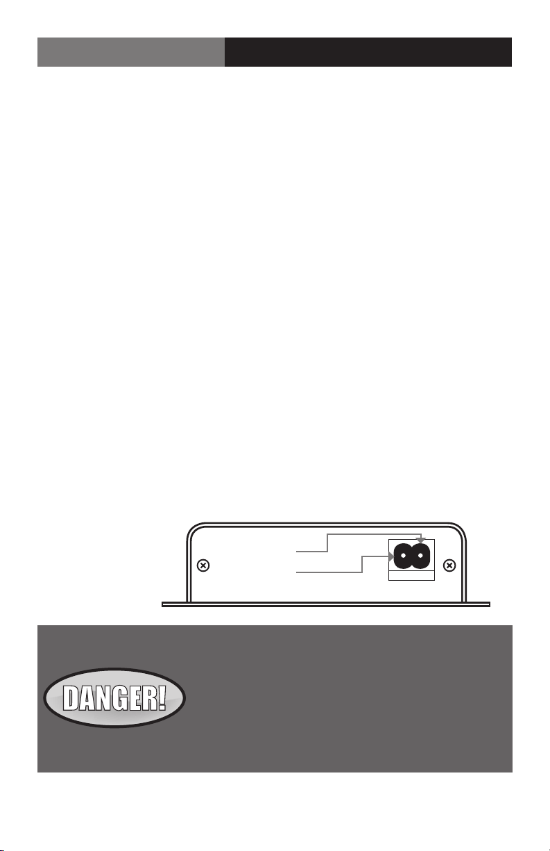
Figure 1:
Power Connector
DC Input Polarity
9-24 Volts
AC or DC
(+) Positive
( - ) Negative
Installation Instructions
The Fiberlink 4040 Series transmission systems are normally preset for immediate use
with audio input circuitry set for balanced 600 Ohm input impedance and output set for
balanced audio. If a dierent protocol is desired, it can be easily selected using the ip
switches located on the back panel of the unit. (See Page 7.) There are indicator LEDs on
the units for monitoring purposes and several user selectable options for conguring audio
inputs and outputs. The following instructions describe the typical installation procedure
and the function of the LED indicators.
The following instructions describe the typical installation procedure:
1) The various options, as already mentioned, have been preset. If unbalanced high-input
impedance or unbalanced output is desired, please refer to instructions on page 7.
2. Connect the ber optic cable between the two Fiberlink units.
3. Apply power to both units. Refer to Figure 1 for DC power connections.
4. When power is applied, the green POWER LED will light, indicating the presence of
operating power.
5. Connect the audio input signals to the proper positions on the removable terminal
blocks. (See Page 8) Be certain to check all connections and assure that inputs and
outputs are not intermixed.
6. The green audio LED indicators (one per channel) will give an indication as stated on
page 9. Note that the rack card version also has a red LED for indicating the presence
of an alarm condition.
Note: The Rack Card version has an additional red LED for indicating the presence of an alarm
condition (loss of signal). Refer to Indicator LED’s and Alarm Circuitry sections of this manual.
Installation Instructions
The transmitting element in the Fiberlink® 4040 transmitter
unit contains a solid state Laser Diode located in the optical
connector. This device emits invisible infrared electromag-
netic radiation which can be harmful to human eyes. The
radiation from this optical connector, if viewed at close
range with no ber optic cable connected to the optical
connector, may be sucient intensity to cause
instantaneous damage to the retina of the eye. Direct
viewing of this radiation should be avoided at all times!