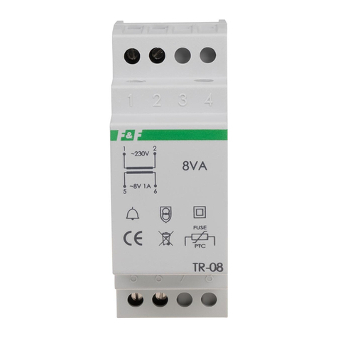
PR electronic 2240 User manual

SIGNALS THE BEST
(8182)63-90-72
(7172)727-132
(8512)99-46-04
(3852)73-04-60
(4722)40-23-64
(4832)59-03-52
(423)249-28-31
(844)278-03-48
(8172)26-41-59
(473)204-51-73
(343)384-55-89
(4932)77-34-06
(3412)26-03-58
(843)206-01-48
(4012)72-03-81
(4842)92-23-67
(3842)65-04-62
(8332)68-02-04
(861)203-40-90
(391)204-63-61
(4712)77-13-04
(4742)52-20-81
(3519)55-03-13
(495)268-04-70
(8152)59-64-93
(8552)20-53-41
(831)429-08-12
(3843)20-46-81
(383)227-86-73
(3812)21-46-40
(4862)44-53-42
(3532)37-68-04
(8412)22-31-16
(342)205-81-47
-- (863)308-18-15
(4912)46-61-64
(846)206-03-16
- (812)309-46-40
(845)249-38-78
(8692)22-31-93
(3652)67-13-56
(4812)29-41-54
(862)225-72-31
(8652)20-65-13
(3462)77-98-35
(4822)63-31-35
(3822)98-41-53
(4872)74-02-29
(3452)66-21-18
(8422)24-23-59
(347)229-48-12
(4212)92-98-04
(351)202-03-61
(8202)49-02-64
(4852)69-52-93
: pcn@nt-rt.ru || www.prelectronic.nt-rt.ru
2240 30

TRANSFORMER
Type 2240
CONTENTS
Warnings ...................................... 12
Safety instructions............................... 14
Declaration of Conformity......................... 16
How to dismantle SYSTEM 2200 ................... 17
Applications.................................... 18
Technical characteristics.......................... 18
Mounting...................................... 18
Input ......................................... 18
Output........................................ 18
Electrical specifications........................... 19
Order......................................... 20
Block diagram.................................. 20
Load diagram .................................. 21
BELASTNINGSSKEMA FOR MAX. EFFEKTUDGANG:

SYMBOL IDENTIFICATION
Triangle with an exclamation mark: Warning / demand.
Potentially lethal situations.
The CE mark proves the compliance of the module with
the requirements of the directives.
The double insulation symbol shows that the module is
protected by double or reinforced insulation.
WARNING!
This module is designed for connection to hazardous electric
voltages. Ignoring this warning can result in severe personal
injury or mechanical damage.
To avoid the risk of electric shock and fire, the safety instructions
of this manual must be observed and the guidelines followed.
The electrical specifications must not be exceeded, and the
module must only be applied as described in the following.
Prior to the commissioning of the module, this manual must be
examined carefully.
Only qualified personnel (technicians) should install this module.
If the equipment is used in a manner not specified by the
manufacturer, the protection provided by the equipment may
be impaired.
WARNING!
Until the module is fixed, do not connect hazardous voltages to
the module. The following operations should only be carried out
on a disconnected module and under ESD safe conditions:
Dismantlement of the module for setting of DIP-switches
and jumpers.
General mounting, connection and disconnection of wires.
Troubleshooting the module.
Repair of the module and replacement of circuit breakers
must be done by PR electronics A/S only.
WARNING!
To keep the safety distances, modules with two built-in relays
must not be connected to both hazardous and non-hazardous
voltages on the same module’s relay contacts.
SYSTEM 2200 must be mounted in socket type S3B Releco
(order no 7023).
GENERAL
HAZARD-
OUS
VOLT AGE
INSTAL-
LATION

The following apply to fixed hazardous voltages-connected modules:
The max. size of the protective fuse is 10 A and, together with a power
switch, it should be easily accessible and close to the module. The
power switch should be marked with a label telling it will switch off the
voltage to the module.
CALIBRATION AND ADJUSTMENT:
During calibration and adjustment, the measuring and connection of external
voltages must be carried out according to the specifications of this manual. The
technician must use tools and instruments that are safe to use.
NORMAL OPERATION:
Operators are only allowed to adjust and operate modules that are safely fixed in
panels, etc., thus avoiding the danger of personal injury and damage. This means
there is no electrical shock hazard, and the module is easily accessible.
CLEANING:
When disconnected, the module may be cleaned with a cloth moistened with
distilled water.
LIABILITY:
To the extent the instructions in this manual are not strictly observed, the custom-
er cannot advance a demand against PR electronics A/S that would otherwise
exist according to the concluded sales agreement.
SAFETY INSTRUCTIONS
DEFINITIONS:
Hazardous voltages have been defined as the ranges: 75 to 1500 Volt DC, and
50 to 1000 Volt AC.
Technicians are qualified persons educated or trained to mount, operate, and
also troubleshoot technically correct and in accordance with safety regulations.
Operators, being familiar with the contents of this manual, adjust and operate the
knobs or potentiometers during normal operation.
RECEIPT AND UNPACKING:
Unpack the module without damaging it and make sure that the manual always
follows the module and is always available. The packing should always follow the
module until this has been permanently mounted.
Check at the receipt of the module whether the type corresponds to the one
ordered.
ENVIRONMENT:
Avoid direct sunlight, dust, high temperatures, mechanical vibrations and shock,
as well as rain and heavy moisture. If necessary, heating in excess of the stated
limits for ambient temperatures should be avoided by way of ventilation.
All modules fall under Installation Category II, Pollution Degree 1, and Insulation
Class II.
MOUNTING:
Only technicians who are familiar with the technical terms, warnings, and
instructions in the manual and who are able to follow these should connect the
module.
Should there be any doubt as to the correct handling of the module, please
contact your local distributor or, alternatively,
PR electronics A/S
Mounting and connection of the module should comply with national legislation
for mounting of electric materials, i.e. wire cross section, protective fuse, and
location. Descriptions of Input / Output and supply connections are shown in the
block diagram and side label.

HOW TO DISMANTLE SYSTEM 2200
The back panel of the module is detached from the housing by way of a
screwdriver as shown in picture 1.
On a module with knobs, these may have to be removed before the PCB can be
taken out as shown in picture 2.
After this, the back panel can be pulled out together with the PCB, but please
notice the position of the PCB as there is a number of different positions in the
house. Do not pull the wires unnecessarily, instead pull the PCB, see picture 3.
Switches and jumpers can now be moved.
When assembling the back plate and housing, please make sure no wires are
stuck.
Picture 1: Dismantlement of back plate
and housing
Picture 2: Removal of knobs
Picture 3: Removal of PCBs for adjustment of DIP-switches
and replacement of jumpers.
DECLARATION OF CONFORMITY
As manufacturer
PR electronics A/S
hereby declares that the following product:
Type: 2240
Name: Transformer
is in conformity with the following directives and standards:
The EMC Directive 2004/108/EC and later amendments
EN 61326-1
For specification of the acceptable EMC performance level, refer to the
electrical specifications for the module.
The Low Voltage Directive 2006/95/EC and later amendments
EN 61010-1
The CE mark for compliance with the Low Voltage directive was affixed in the
year: 1997
Kim Rasmussen
Manufacturer’s signature

ELECTRICAL SPECIFICATIONS:
Specifications range:
-20°C to +60°C
Common specifications:
Isolation, test / operation ............................ 3.75 kVAC / 250 VAC
Power derating ............................................ Tamb. > 25°C, 0.4 VA/°C
EMC immunity influence ............................. < ±0.5% of span
Relative air humidity .................................... < 95% RH (non-cond.)
Dimensions (HxWxD) ................................... 80.5 x 35.5 x 84.5 mm
Protection degree ........................................ IP50
Weight ......................................................... 600 g
Input:
Primary voltage ........................................... 207...253 VAC
97.75...132.25 VAC
Frequency .................................................... 50...60 Hz
Output:
Secondary voltage (loaded) ........................ 24 VAC / 1.25 A
Secondary voltage (unloaded) .................... 28 VAC
Secondary voltage (loaded) ........................ 12 VAC / 2.50 A
Secondary voltage (unloaded) .................... 14 VAC
GOST R approval:
VNIIM
Observed authority requirements: Standard:
EMC 2004/108/EC ...................................... EN 61326-1
LVD 2006/95/EC .......................................... EN 61010-1
PELV/SELV ................................................... IEC 364-4-41 and EN 60742
Of span = Of the presently selected range
TRANSFORMER 2240
• Double-isolated transformer
• 3.75 kVAC isolation voltage
• 30 VA ring core transformer
• Thermal overload protection
• 12 or 24 VAC secondary voltage
• Standard 11-pole relay socket
APPLICATIONS:
Transformer for supply of components with 12 or 24 VAC supply voltage.
Transformer for stabilised DC power supplies, e.g. type 2229.
TECHNICAL CHARACTERISTICS:
Ring core transformer with separate 3.75 kVAC isolation voltage between primary
and secondary windings. The transformer is fitted with a thermal 100°C fuse.
Two transformers may be paralleled for higher output power. The transformer is
molded into the cassette and should be mounted with 10 mm distance to the
adjacent cassette for optimal cooling.
The load diagram shows the relation between the ambient temperature and
maximum VA output. The module is supplied with a retention clip for a safe
attachment to the relay socket.
MOUNTING:
The 2240 is for standard 11-pole socket mounting in all positions. To achieve
maximum cooling of the module, mounting in a vertical position at a distance of
10 mm between neighbouring units is recommended.
INPUT:
Standard primary voltages of 115 or 230 VAC. Special primary voltages may be
delivered, but are not kept in stock.
OUTPUT:
Standard secondary voltages of 12 or 24 VAC. Max DC power after rectifica tion
and stabilisation: 20 W. Special secondary voltages may be delivered, but are
not kept in stock.

LOAD DIAGRAM FOR MAX. POWER OUTPUT
ORDER:
BLOCK DIAGRAM:
Type Input Output
2240 115 VAC
230 VAC
Special
: A
: B
: X
Special
24 VAC
12 VAC
: 0
: 1
: 2

:
(8182)63-90-72
(7172)727-132
(8512)99-46-04
(3852)73-04-60
(4722)40-23-64
(4832)59-03-52
(423)249-28-31
(844)278-03-48
(8172)26-41-59
(473)204-51-73
(343)384-55-89
(4932)77-34-06
(3412)26-03-58
(843)206-01-48
(4012)72-03-81
(4842)92-23-67
(3842)65-04-62
(8332)68-02-04
(861)203-40-90
(391)204-63-61
(4712)77-13-04
(4742)52-20-81
(3519)55-03-13
(495)268-04-70
(8152)59-64-93
(8552)20-53-41
(831)429-08-12
(3843)20-46-81
(383)227-86-73
(3812)21-46-40
(4862)44-53-42
(3532)37-68-04
(8412)22-31-16
(342)205-81-47
-- (863)308-18-15
(4912)46-61-64
(846)206-03-16
- (812)309-46-40
(845)249-38-78
(8692)22-31-93
(3652)67-13-56
(4812)29-41-54
(862)225-72-31
(8652)20-65-13
(3462)77-98-35
(4822)63-31-35
(3822)98-41-53
(4872)74-02-29
(3452)66-21-18
(8422)24-23-59
(347)229-48-12
(4212)92-98-04
(351)202-03-61
(8202)49-02-64
(4852)69-52-93
: pcn@nt-rt.ru || www.prelectronic.nt-rt.ru
Table of contents
Popular Transformer manuals by other brands
Huawei
Huawei STS-6000K-H1 installation guide
Iwatsu
Iwatsu Rogowski Coil Current Probe instruction manual
Monacor
Monacor CARPOWER FGA-40 operating instructions

Heitronic
Heitronic 20035 Installation and operating instructions
ORTEA NEXT
ORTEA NEXT ICAR MICROmatic HP10 Series Installation, operating and maintenance manual
Audio Technica
Audio Technica AT-SUT1000 user manual
