LD Didactic 773 363 User manual

© by LD DIDACTIC GmbH · Leyboldstraße 1 · D-50354 Hürth · www.ld-didactic.com
Tel: +49-2233-604-0 · Fax: +49-2233-604-222 · Email: [email protected] · Technical alterations reserved
•
•
•
•
•
•
•
•
•
•
•
•
•
•
•
•
•
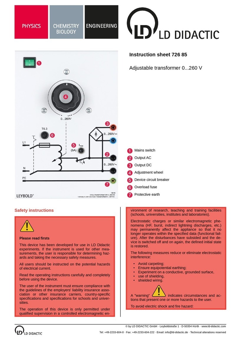
Instruction sheet 773 363
Controllable capacitive load 1 kW
Mains switch
Inputs L1, L2 and L3
N / neutral point
Analog control input
Controls SET / OFF
step selector UP / DOWN
LED status bar
Overview table and legend
Safety instructions
Please read first
This device has been developed for use in LD Didactic
experiments. If the instrument is used for other mea
surements, the user is responsible for determining haz
ards and taking the necessary safety measures.
All users should be instructed on the potential hazards
of electrical current.
Read the operating instructions carefully and completely
before using the device.
The user of the instrument must ensure compliance with
the guidelines of the employers' liability insurance asso
ciation or other insurance carriers, country-specific
specifications and specifications for schools and univer
sities.
The operation of this device is only permitted under
qualified supervision in a controlled electromagnetic en
vironment of research, teaching and training facilities
(schools, universities, institutes and laboratories).
Electrostatic charges or similar electromagnetic phe
nomena (HF, burst, indirect lightning discharges, etc.)
may permanently affect the appliance so that it no
longer operates within the specified data (functional fail
ure). After the disturbances have subsided and the de
vice is switched off and on again, the defined initial state
is restored.
The following measures reduce or eliminate electrostatic
interference:
Avoid carpeting;
Ensure equipotential earthing;
Experiment on a conductive, grounded surface,
use of shielding,
shielded wiring.
The appliance complies with the following standards:
Safety requirements for electrical equipment for mea
surement, control and laboratory use, Part 1: General
requirements
Rated voltage range: 230V
CAT III 300
Pollution level 2.
Use the appliance and accessories only as speci
fied in the instructions for use. Failure to follow
these instructions may result in impairment of the
protective functions provided.
A "warning“ indicates circumstances and ac
tions that present one or more hazards to the user.
To avoid electric shock and fire hazard:
Read the entire manual carefully before using the
instrument and accessories.
Read all instructions carefully.
Do not work alone.
Do not use the appliance near explosive gases,
vapours or in humid or wet environments.
Use the product only as intended. Otherwise, the
protection provided by the product may be im
paired.
Only use safety leads rated for the maximum val
ues of the product.
When using test probes, keep your fingers behind
the fingerguards on the test probes.
Check the instrument, test leads and accessories
for any mechanical damage before use and replace
if necessary. Check if there are any cracks in the in
sulation (housing, cable sheath) or if any parts are

2 / 5 Instructionsheet773363
© by LD DIDACTIC GmbH · Leyboldstraße 1 · D-50354 Hürth · www.ld-didactic.com
Tel: +49-2233-604-0 · Fax: +49-2233-604-222 · Email: [email protected] · Technical alterations reserved
•
•
•
•
•
•
•
•
•
•
•
•
•
•
•
•
•
•
•
•
•
•
•
•
•
•
•
•
•
•
•
missing. Pay particular attention to the insulation on
the connectors.
Remove all unused test leads and accessories.
Always connect the unit to the wall socket first be
fore connecting it in the experimental setup.
Do not disconnect any supply lead or the mains ca
ble during operation. Danger of arcing.
Only switch off the unit in load level 0 or in OFF sta
tus.
Do not touch voltages >25V AC effective or 60V
DC.
When measuring, use only the correct measuring
category (CAT), voltage- as well as amperage-test
ed measuring leads and adapters.
Never exceed the rated values of the measuring
category (CAT) for the lowest rated individual com
ponent of a product, a test lead or an accessory.
Comply with local and national safety regulations.
Use personal protective equipment (approved rub
ber gloves, face shield and flame retardant cloth
ing) to prevent electrical shock and burn injuries in
the event that hazardous live conductors are ex
posed.
Only open the appliance when it is de-energised.
Do not operate the unit when the covers are re
moved or the housing is open. You could come into
contact with dangerous voltages.
Do not use BNC or banana plugs made of bare
metal.
Never insert any metal objects into the connectors.
During operation at high load levels, the ex
haust air of the unit may become hot.
The experiments must not be carried out if
the equipment shows visible damage.
the product has been dropped.
the housing cover is missing.
devices and machines of protection class I are not
connected to the mains protective conductor.
The instrument must not be used
in damp or wet rooms.
in rooms with flammable gases, vapours or dust.
in rooms with explosion hazards.
outdoors.
Avoid
knocks, bumps and shaking.
touching the equipment with wet hands.
the intrusion of liquids.
overloads and short circuits.
heat build-up by covering the vents.
Feeding the equipment from power supply points
that do not belong to the experimental stands.
tripping hazards due to power supply cables lying
around.
Make sure that
the connection of the devices or circuit changes in
the experimental setup may only be carried out in a
de-energised state. The voltage source must be
switched off.
the equipment is only cleaned when it is de-ener
gised.
only original spare parts are used for any neces
sary repairs.
1 Description and intended use
The controllable capacitive load is a universally applicable ex
perimental device that represents an electrical consumer. The
power consumption is up to 1.3var.
The main application is as an adjustable load in three-phase
networks or as a controllable load for generators. The load is
particularly suitable for teaching the basics of power electron
ics and power engineering to trainees and students.
The capacitance of each phase is individually adjustable in 15
steps from 1.7µFto 26.3µF.Phase separation occurs in step
0. The step and status display of the load is via coloured LED
strips on the front.
There are three different operating modes.
1.1 Direct manual control
In this stand-alone mode, no further control devices are re
quired and the load can be easily integrated into existing con
figurations. The control is carried out directly on the unit via
push-buttons (step switch UP / DOWN ). Both symmetri
cal and asymmetrical loads are possible.
1.2 Remote control
Via the analog control input the load can be controlled
remotely, e.g. with the Power Analyser CASSY Plus. This al
lows direct and balanced control of the steps as well as trig
gered or scenario-based switching of the capacitors. Both the
CASSY Lab 2 measurement software and the Lab Docs inter
active instruction sheets can be used to control the loads via
the CASSY Plus power analyser. Scenarios are made possi
ble by the LabView support of the Power Analyser CASSY
Plus. Via the analog control input, the unit can be used univer
sally, e.g. in control engineering.
1.3 Triggered switching
It is also possible to switch on a user-defined unbalanced or
balanced load with an external trigger via the control input
. In this way, the influence of such loads on e.g. transform
ers or generators can be investigated and demonstrated.
2 Set up
Connect a power cable to the back of the load.

Instructionsheet773363 3 / 5
© by LD DIDACTIC GmbH · Leyboldstraße 1 · D-50354 Hürth · www.ld-didactic.com
Tel: +49-2233-604-0 · Fax: +49-2233-604-222 · Email: [email protected] · Technical alterations reserved
•
•
•
•
•
•
•
•
•
3 Technical data
Capacitance per
phase adjustable in 15 steps
1.7µF/3.4µF/5.1µF/7.0µF/
8.8µF/10.5µF/12.1µF/
14.1µF/15.8µF/17.5µF/
19.2µF/21.1µF/22.9µF/
24.6µF/26.3µF
With 400 V three-phase current
in star connection, this
corresponds to a maximum
powerof437varperphase.
Tolerated mains
overvoltage load
part 230V+10%
Isolation in step 0 >1MΩ
C tolerance ±5%
Inputs 4mmsafetysockets
Overvoltage
category CATIII300V
Voltage control
input
10V...+10VMainsvoltage
proof
Microfuses T1Aatthemainsconnection
Housing 400 mm table-top unit (also
suitable for experimental frames)
Dimensions
(HxWxD) 300mmx400mmx180mm
Mass approx. 5.2kg
Operating voltage 115V/230V50Hz
Fan load-controlled
Overtemperature
sensors
with automatic switch-off and
error display
3.1 Scope of delivery
Controllable capacitive load 1 (773 363)
Power cord
4 Description of the assembly
4.1 Connectors L1, L2, L3 und N
For connecting the phases and neutral. With 400V three-
phase current, the load is designed to be connected in a star.
Use bridging plugs to establish a connection to the star point.
In delta connection, the user must ensure that
the maximum tolerated voltage on each phase of
230V+10%is not exceeded!
The connections are implemented on both sides of the load
and short-circuited with each other, so that a simple extension
of the experimental setup is possible.
4.2 Analog control input
Control input for remote control of the load. Valid control sig
nals are in the interval between 10Vund +10V.The input is
mains voltage tolerant and thus protected against incorrect
wiring.
4.3 Controls SET / OFF
With SET a load manually configured by the user is switched
active.
OFF allows the load to be disconnected in any state.
4.4 Step Switch UP / DOWN
UP increases the preselected step, DOWN decreases it. Each
phase can be set independently. Alternatively, phases can be
paired with each other and load steps can thus be switched si
multaneously on several phases with one key press.
4.5 LED status bar
The status of the load is displayed for each phase by the cor
responding LED strip. Each bar consists of 8 LEDs.
The steps are displayed in bar form with lit or flashing LEDs. A
flashing LED indicates that the smaller step printed to the left
is active. A continuously lit LED means that the larger step is
active. For example: For step 1, the first LED of the bar flash
es, in step 2 it is lit continuously.
The LED colours are assigned as follows:
Colour coding of the LED status bars.
Non paired phases and reference phase:
Active step: Cyan
Preselected step higher than active step: Blue
Preselected step lower than active step: Green
Paired phases:
Active step: White
Preselected step higher than active step: Purple
Preselected step lower than active step: Orange
Ready for pairing: Purple flashing
Error states such as overtemperature are indicated with red
LEDs.
4.6 Fuses
Fuse for the IEC socket on the rear T 1A250Vmicrofuse.
4.7 Additional features
For cooling purposes, fans regulated according to the set load
step are used. This also allows continuous operation.
Fig. 1:

4 / 5 Instructionsheet773363
© by LD DIDACTIC GmbH · Leyboldstraße 1 · D-50354 Hürth · www.ld-didactic.com
Tel: +49-2233-604-0 · Fax: +49-2233-604-222 · Email: [email protected] · Technical alterations reserved
•
•
•
•
•
•
•
•
•
In order to detect a critical overload, the phases are also indi
vidually temperature-monitored.
An internal phase detection system ensures switching at zero
voltage, making experiments easily reproducible.
5 Operation
Switching on via the mains switch .
When switched on, the load goes through an internal test, the
LEDs on the front flash in different colours.
Only switch the unit off using the mains
switch if the load has been disconnected beforehand
using the OFF button.
5.1 Mode 1: Direct manual control
The load can be set individually for each phase.
The pre-selection of the load level is made with the UP /
DOWN buttons .
Pressing the SET button activates the set steps.
With OFF the load is immediately dropped complete
ly.
Unbalanced loads are possible in this mode.
The user must ensure that such loads do not generate
dangerous operating conditions such as overvoltage or
overload and may damage the load or other compo
nents.
A preselection of the stages and switching via SET is also
possible when the load is active.
Pairing phases
To control all phases or any pairs of phases simultaneously,
they can be paired with each other. One phase is used as a
reference.
Press the UP and DOWN buttons of the desired phase at
the same time. The LEDs of the phase flash purple.
Press the UP button of the reference phase.
The status LEDs of the paired phase change colour as
described above.
The remaining phase can also be paired to the reference
phase.
The pairing is released by simultaneously pressing UP and
DOWN on the paired phase.
5.2 Mode 2: Remote control
Via the analog control input all three phases can be
switched symmetrically at the same time. The active step can
be selected with the DC voltages given in the following table.
By applying the voltage, the corresponding step is immediate
ly switched to active on all phases.
Step Voltage (V) DC
0 2
1 2.5
2 3
3 3.5
4 4
5 4.5
6 5
7 5.5
8 6
9 6.5
10 7
11 7.5
12 8
13 8.5
14 9
15 9.5
Mode 2 is active above a control voltage ≥1.9V.In this mode,
the load can no longer be controlled manually on the unit.
However, the OFF button for disconnecting the load is still ac
tive. After the load has been switched off with the OFF button
the load is blocked against being switched on remotely and
must first be released again with the SET button.
Remote control with Power Analyser CASSY Plus
It is recommended to control the load remotely using the Pow
er Analyser CASSY Plus in combination with the measure
ment software CASSY Lab 2 or Lab Docs.
Connect one of the outputs U - X of the Power Analyser
CASSY Plus to the control input of the load. Make sure
that the polarity is correct.
In CASSY Lab 2, activate the Load L function at the cor
responding output.
Select the step range 0 ... 15 and the desired load step,
as shown for example in the illustration for level 5 at out
put U (load LU).
Screenshot from CASSY Lab 2 with setting for load level 5
at output U.
With a tick in "Switch automatically only during measurement",
the load can be switched on with a delay. Define the delay af
Fig. 2:

Instructionsheet773363 5 / 5
© by LD DIDACTIC GmbH · Leyboldstraße 1 · D-50354 Hürth · www.ld-didactic.com
Tel: +49-2233-604-0 · Fax: +49-2233-604-222 · Email: [email protected] · Technical alterations reserved
•
•
•
•
•
ter the start of the measurement in seconds in the field "De
lay:"
A demo version of CASSY Lab 2 (524 220) can be obtained
from the LD Didactic website: Download CASSY Lab 2.
In a similar way, it is also possible to control the load in the
GUI of the Power Analyser CASSY Plus.
Connect one of the outputs U - X of the Power Analyser
CASSY Plus to the control input of the load. Pay attention
to the correct polarity.
Use the rotary switch to activate the corresponding output
on the Power Analyser CASSY Plus and select Load.
Select the step range 0 ... 15 and the desired load level.
5.3 Mode 3: External trigger
In this mode, a user preselected unbalanced or balanced load
can be switched on with an external trigger at the control in
put.
Select the desired pre-set with the UP / DOWN buttons
.
The load is switched on when the control voltage is in the
interval between 8.5Vand 9.5V.It will switch off again
when the voltage leaves this interval. Voltages < 9.5V
are ignored.
Again, the load can be disconnected in this mode by pressing
the OFF button. It must then be released again with SET.
In CASSY Lab 2, the mode is accessible with the range selec
tion 0 ... 1. At level 0, the load is switched off, level 1 triggers
the load.
6 Disposal
Electrical and electronic products must not be disposed of with
household waste. Dispose of the product in accordance with
the applicable legal regulations.
7 Technical supplements
7.1 Overview of load steps at nominal conditions
Step Capacitance
(µF) + / - 5%
Power
per
phase
(var)
Total power
consumed
(var)
0 0 0 0
1 1.7 28 85
2 3.4 57 170
3 5.1 85 254
4 7 116 349
5 8.8 146 439
6 10.5 174 523
7 12.1 201 603
8 14.1 234 703
9 15.8 263 788
10 17.5 291 872
11 19.2 319 957
12 21.1 351 1052
13 22.9 381 1142
14 24.6 409 1226
15 26.3 437 1311
Table of contents
Other LD Didactic Transformer manuals
Popular Transformer manuals by other brands

Roger
Roger PS-10ACDR operating manual

Cloud
Cloud CXL-80T installation instructions

Zenith
Zenith 122C-A - Heath - Lock-Nut Transformer installation instructions

DX Engineering
DX Engineering Maxi-Core DXE-BAL050-Series quick start guide

Phasemation
Phasemation T-1000 owner's manual

AUTOMATION 2000
AUTOMATION 2000 DGPT2 Series Technical instructions

Allen-Bradley
Allen-Bradley 193-CT-CE-300A installation instructions

Bego
Bego 17800 Translation of the original instructions

ABB
ABB VT Guard Pro Instructions for installation, use and maintenance

Inlite
Inlite SMART HUB-150 installation manual

IMG STAGE LINE
IMG STAGE LINE FGA-102 instruction manual

Lamarche
Lamarche ITSM Installation and operation manual