PR electronics 2288 User manual
Programmable displays with a wide se-
lection of inputs and outputs for display of temperature,
volume and weight, etc. Feature linearisation, scaling,
and difference measurement functions for programming
via PReset software.
Interfaces for analogue and digital
signals as well as HART®signals between sensors / I/P
converters / frequency signals and control systems in Ex
zone 0, 1 & 2 and for some modules in zone 20, 21 & 22.
Galvanic isolators for analogue and digital
signals as well as HART®signals. A wide product range
with both loop-powered and universal isolators featuring
linearisation, inversion, and scaling of output signals.
PC or front programmable modules with
universal options for input, output and supply. This range
offers a number of advanced features such as process
calibration, linearisation and auto-diagnosis.
A wide selection of transmitters for DIN
form B mounting and DIN rail modules with analogue
and digital bus communication ranging from application-
specific to universal transmitters.
Displays
Temperature
Isolation
Ex interfaces
Universal
DK
UK
FR
DE
Side 1
Page 13
Page 25
Seite 37
SIGNALS THE BEST
2288
Pulse Interface
No. 2288V101-IN (0834)
From ser. no. 970426001

IMPULSINTERFACE
TYPE 2288
INDHOLDSFORTEGNELSE
Advarsler . . . . . . . . . . . . . . . . . . . . . . . . . . . . . . . . . . . . . . 2
Sikkerhedsregler . . . . . . . . . . . . . . . . . . . . . . . . . . . . . . . . 3
Overensstemmelseserklæring. . . . . . . . . . . . . . . . . . . . . . 5
Adskillelse af SYSTEM 2200. . . . . . . . . . . . . . . . . . . . . . . 6
Anvendelse . . . . . . . . . . . . . . . . . . . . . . . . . . . . . . . . . . . . 7
Teknisk karakteristik . . . . . . . . . . . . . . . . . . . . . . . . . . . . . 7
Indgang . . . . . . . . . . . . . . . . . . . . . . . . . . . . . . . . . . . . . . . 7
Udgange . . . . . . . . . . . . . . . . . . . . . . . . . . . . . . . . . . . . . . 7
Elektriske specifikationer. . . . . . . . . . . . . . . . . . . . . . . . . . 8
Bestillingsskema . . . . . . . . . . . . . . . . . . . . . . . . . . . . . . . . 10
Blokdiagram . . . . . . . . . . . . . . . . . . . . . . . . . . . . . . . . . . . 10
Programmering . . . . . . . . . . . . . . . . . . . . . . . . . . . . . . . . . 11
1
SIKKERHEDSREGLER
DEFINITIONER:
Farlige spændinger er defineret som områderne: 75...1500 Volt DC og 50...1000
Volt AC.
Teknikere er kvalificerede personer, som er uddannet eller oplært til at kunne
udføre installation, betjening eller evt. fejlfinding både teknisk og sikkerheds-
mæssigt forsvarligt.
Operatører er personer, som under normal drift med produktet skal indstille og
betjene produktets trykknapper eller potentiometre, og som er gjort bekendt med
indholdet af denne manual.
MODTAGELSE OG UDPAKNING:
Udpak modulet uden at beskadige dette, og sørg for, at manualen altid følger
modulet og er tilgængelig. Indpakningen bør følge modulet, indtil dette er mon-
teret på blivende plads.
Kontrollér ved modtagelsen, at modultypen svarer til den bestilte.
MILJØFORHOLD:
Undgå direkte sollys, kraftigt støv eller varme, mekaniske rystelser og stød, og
udsæt ikke modulet for regn eller kraftig fugt. Om nødvendigt skal opvarmning,
udover de opgivne grænser for omgivelsestemperatur, forhindres ved hjælp af
ventilation.
Alle moduler hører til Installationskategori II, Forureningsgrad 1 og Isolations-
klasse II.
INSTALLATION:
Modulet må kun tilsluttes af teknikere, som er bekendte med de tekniske udtryk,
advarsler og instruktioner i manualen, og som vil følge disse.
Hvis der er tvivl om modulets rette håndtering, skal der rettes henvendelse til den
lokale forhandler eller alternativt direkte til:
PR electronics A/S, Lerbakken 10, DK-8410 Rønde tlf: +45 86 37 26 77.
Installation og tilslutning af modulet skal følge landets gældende regler for instal-
lation af elektrisk materiel bl. a. med hensyn til ledningstværsnit, for-sikring og
placering.
Beskrivelse af indgang / udgang og forsyningsforbindelser findes på blok-
diagrammet og sideskiltet.
32
ADVARSEL
Dette modul er beregnet for tilslutning til livsfarlige elektriske
spændinger. Hvis denne advarsel ignoreres, kan det føre til alvorlig
legemsbeskadigelse eller mekanisk ødelæggelse. For at undgå
faren for elektriske stød og brand skal manualens sikkerhedsregler
overholdes, og vejledningerne skal følges. De elektriske specifi-
kationer må ikke overskrides, og modulet må kun benyttes som
beskrevet i det følgende. Manualen skal studeres omhyggeligt,
før modulet tages i brug. Kun kvalificeret personale (teknikere) må
installere dette modul. Hvis modulet ikke benyttes som beskrevet i
denne manual, så forringes modulets beskyttelsesforanstaltninger.
GENERELT
ADVARSEL
Der må ikke tilsluttes farlig spænding til modulet, før dette er fast-
monteret, og følgende operationer på modulet bør kun udføres i
spændingsløs tilstand og under ESD-sikre forhold:
Adskillelse af modulet for indstilling af omskiftere og jumpere.
Installation, ledningsmontage og -demontage.
Fejlfinding på modulet.
Reparation af modulet og udskiftning af sikringer må kun
foretages af PR electronics A/S.
FARLIG
SPÆNDING
ADVARSEL
For at overholde sikkerhedsafstande må moduler med to indbyg-
gede relæer ikke tilsluttes både farlig og ikke-farlig spænding på
samme moduls relækontakter.
SYSTEM 2200 monteres i sokkel type S3B Releco (bestillings-
nummer 7023).
INSTAL-
LATION
Trekant med udråbstegn: Advarsel / krav. Hændelser der kan
føre til livstruende situationer.
CE-mærket er det synlige tegn på modulets overensstemmelse
med direktivernes krav.
Dobbelt isolation er symbolet for, at modulet overholder ekstra
krav til isolation.
SIGNATURFORKLARING

5
OVERENSSTEMMELSESERKLÆRING
Som producent erklærer
PR electronics A/S
Lerbakken 10
DK-8410 Rønde
hermed at følgende produkt:
Type: 2288
Navn: Impulsinterface
er i overensstemmelse med følgende direktiver og standarder:
EMC-direktivet 2004/108/EF og senere tilføjelser
EN 61326
For specifikation af det acceptable EMC-niveau henvises til modulets
elektriske specifikationer.
Lavspændingsdirektivet 2006/95/EF og senere tilføjelser
EN 61010-1
CE-mærket for overensstemmelse med lavspændingsdirektivet blev tilføjet i
året: 1997
Rønde, 18. okt. 2007 Peter Rasmussen
Producentens underskrift
For moduler, som er permanent tilsluttet farlig spænding, gælder:
For-sikringens maksimale størrelse er 10 A og skal sammen med en afbry-
der placeres let tilgængelig og tæt ved modulet. Afbryderen skal mærkes
således, at der ikke er tvivl om, at den afbryder spændingen til modulet.
KALIBRERING OG JUSTERING:
Under kalibrering og justering skal måling og tilslutning af eksterne spændinger
udføres i henhold til denne manual, og teknikeren skal benytte sikkerheds-mæs-
sigt korrekte værktøjer og instrumenter.
BETJENING UNDER NORMAL DRIFT:
Operatører må kun indstille eller betjene modulerne, når disse er fast installeret
på forsvarlig måde i tavler el. lignende, så betjeningen ikke medfører fare for liv
eller materiel. Dvs., at der ikke er berøringsfare, og at modulet er placeret, så det
er let at betjene.
RENGØRING:
Modulet må, i spændingsløs tilstand, rengøres med en klud let fugtet med destil-
leret vand.
ANSVAR:
I det omfang, instruktionerne i denne manual ikke nøje er overholdt, vil kunden
ikke kunne rette noget krav, som ellers måtte eksistere i henhold til den indgåede
salgsaftale, mod PR electronics A/S.
4

IMPULSINTERFACE 2288
• Impulsforlænger
• Impulsinverter
• Impulsforstærker
• Programmerbare funktioner
• S0-indgang
• Indbygget NAMUR-forsyning
ANVENDELSE:
Impulsforlænger til brug i processer, hvor man har korte impulser, og det tilslut-
tede udstyr har lang scantid. • Tilpasningsled mellem standard impulsgivere og
relæ, elektromekanisk tæller o.lign. • Forstærker for induktive, kapacitive og
optiske følere.
TEKNISK KARAKTERISTIK:
INDGANG:
Programmerbar indgang for tilslutning af standard impulsgivere, samt NAMUR-
indgang i henhold til DIN 19234 og S0-indgang efter DIN 43864.
Ved kontaktindgang bør filter 10 ms / 50 Hz indkobles.
Indgang kan programmeres til trig på for- eller bagkant af indgangsimpuls.
UDGANGE:
Udgange PNP, NPN, TTL samt optokoblet NPN. TTL-udgang er beskyttet med
PTC-modstand.
Udgangsimpulstid kan programmeres som direkte impuls (udgangsimpulsbredde
= indgangsimpulsbredde).
Den variable impulsbredde er justerbar i 2 områder mellem 10...100 og 100...1000
ms. Fast impulsbredde = 50 ms.
Lysdiode i front indikerer signal på indgang.
Aktiv udgang etableres ved at forbinde PNP til NPN-udgangen, samt invertere
NPN-udgangen (JP8 1-2).
7
ADSKILLELSE AF SYSTEM 2200
Billede 1:
Modulets bagplade frigøres fra huset
ved hjælp af en skruetrækker.
Billede 2:
Derefter kan bagpladen udtræk-
kes sammen med printet, men vær
opmærksom på printets placering
i huset, da det er muligt at isætte
dette i flere positioner. Træk ikke
unødigt i ledningerne, men tag fat
i printet.
Nu kan switche og jumpere ændres.
Det er vigtigt, at ingen ledninger
kommer i klemme, når bagplade og
huset samles.
6

9
Optokoblet udgang:
Max. frekvens.............................................. 5 kHz
Impulsbredde .............................................. ≥0,1 ms
Belastning.................................................... 100 mA / 30 VDC
Spændingsdrop ved 25 mA / 100 mA ........ < 2,0 VDC / < 4 VDC
Isolation test / drift ...................................... 1,4 kVAC / 150 VAC
GOST R godkendelse:
VNIIM, Cert. no............................................ Ross DK.ME48.V01899
Overholdte myndighedskrav: Standard:
EMC 2004/108/EF
Emission og immunitet.................. EN 61326
LVD 2006/95/EF .......................................... EN 61010-1
ELEKTRISKE SPECIFIKATIONER:
Specifikationsområde:
-20°C til +60°C
Fælles specifikationer:
Forsyningsspænding................................... 19,2...28,8 VDC
Egetforbrug ................................................. 1 W
Kalibreringstemperatur................................ 20...28°C
Hjælpespændinger:
NAMUR ................................................... 8 VDC, Imax.: 8 mA
S0............................................................ Max. 27 VDC, Imax. 27 mA,
Imin. 800 Ω belastning 10 mA
EMC-immunitetspåvirkning......................... < ±0,5%
Relativ fugtighed ......................................... < 95% RF (ikke kond.)
Mål (HxBxD) ................................................ 80,5 x 35,5 x 84,5 mm
Kapslingsklasse........................................... IP50
Vægt............................................................ 115 g
Elektriske specifikationer
Indgang:
Max. frekvens.............................................. 10 kHz
Min. impulsbredde ...................................... 50 µs
Max. frekvens (med indgangsfilter)............. 50 Hz
Min. impulsbredde
(med indgangsfilter)..................................... 10 ms
Udgang:
Udgangsspænding:
PNP......................................................... Vforsyning -1,5 VDC
NPN......................................................... Max. 30 VDC
NPN RON ................................................. 30 Ω
TTL .......................................................... 5 VDC ±0,5 V
Udgangsstrøm:
PNP, NPN................................................ 100 mA (140 mA i 50 ms ved
50% duty cycle)
TTL .......................................................... 10 mA
Minimum impulslængde.............................. 50 µs
Maksimum impulslængde ........................... 1 s
8

11
PROGRAMMERING:
JUMPERPROGRAMMERING
ON OFF
Bagkant JP1 JP2
Forkant JP2 JP1
Impulsbredde 1:1 JP3 JP4, JP5
Fast impulsbredde 50 ms JP5 JP3, JP4
Justerbar impulsbredde JP4 ON og JP3, JP5
10...100 ms JP9 i pos. 2-3
100...1000 ms JP9 i pos. 1-2
Direkte udgang JP6 i pos. 1-2
Inverteret udgang JP6 i pos. 2-3
NAMUR-forsyning JP7 i pos. 1-2
S0-forsyning JP7 i pos. 2-3
Aktiv udgang JP8 i pos. 1-2
Normal udgang JP8 i pos. 2-3
10
BESTILLINGSSKEMA:
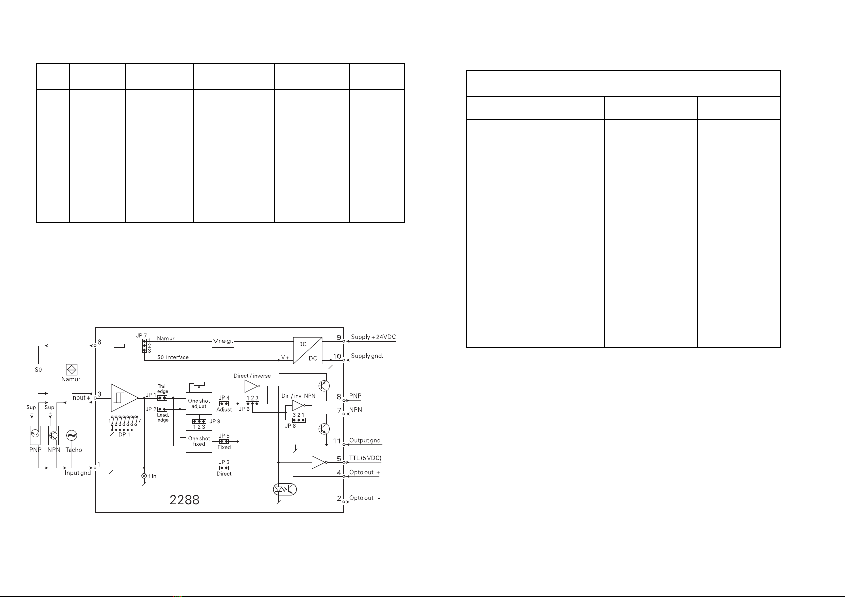
BLOKDIAGRAM:
Type Føler Indgangs-
filter
Triging Udgangs-
impulsbredde
Udgang
2288 Tacho : A
NAMUR : B
NPN : C
PNP : D
TTL : E
S0 : F
Speciel : X
Specielt : 0
> 10 ms : 1
(max. 50 Hz)
Intet : 2
Bagkant : A
Forkant : B
Speciel : 0
Direkte : 1
Justerbar : 2
(10...1000 ms)
Fast (50 ms) : 3
Direkte : A
Inverteret : B

PULSE INTERFACE
TYPE 2288
CONTENTS
Warnings . . . . . . . . . . . . . . . . . . . . . . . . . . . . . . . . . . . . . . 14
Safety instructions. . . . . . . . . . . . . . . . . . . . . . . . . . . . . . . 15
Declaration of Conformity . . . . . . . . . . . . . . . . . . . . . . . . . 17
How to dismantle SYSTEM 2200 . . . . . . . . . . . . . . . . . . . 18
Applications. . . . . . . . . . . . . . . . . . . . . . . . . . . . . . . . . . . . 19
Technical characteristics . . . . . . . . . . . . . . . . . . . . . . . . . 19
Input . . . . . . . . . . . . . . . . . . . . . . . . . . . . . . . . . . . . . . . . . 19
Outputs . . . . . . . . . . . . . . . . . . . . . . . . . . . . . . . . . . . . . . . 19
Electrical specifications. . . . . . . . . . . . . . . . . . . . . . . . . . . 20
Order . . . . . . . . . . . . . . . . . . . . . . . . . . . . . . . . . . . . . . . . . 22
Block diagram . . . . . . . . . . . . . . . . . . . . . . . . . . . . . . . . . . 22
Programming. . . . . . . . . . . . . . . . . . . . . . . . . . . . . . . . . . . 23
1312
DP1: INDGANGSTYPE
INDGANG ON OFF
Tacho 5 1, 2, 3, 4, 7
NAMUR 3, 5 1, 2, 4, 7
og JP7 i 1-2
NPN 1 2, 3, 4, 5, 7
PNP 2 1, 3, 4, 5, 7
TTL 4 1, 2, 3, 5, 7
S0 (DIN 43864) 3, 6, 7 1, 2, 4, 5
og JP7 i 2-3
Indgangsfilter:
> 10 ms / max. 50 Hz 6
Føler Trig-niveau Indgangs-
modstand
VTL VTH
Tacho 200 mV 350 mV > 100 kΩ
NAMUR 1,2 mA 2,1 mA
NPN, PNP 4,5 V 5,5 V 3,3 kΩ
TTL 0,8 V 2,0 V > 100 kΩ
S0-indgang 2,2 mA 9,0 mA
15
SYMBOL IDENTIFICATION
Triangle with an exclamation mark: Warning / demand.
Potentially lethal situations.
The CE mark proves the compliance of the module with
the requirements of the directives.
The double insulation symbol shows that the module is
protected by double or reinforced insulation.
SAFETY INSTRUCTIONS
DEFINITIONS:
Hazardous voltages have been defined as the ranges: 75 to 1500 Volt DC, and
50 to 1000 Volt AC.
Technicians are qualified persons educated or trained to mount, operate, and
also troubleshoot technically correct and in accordance with safety regulations.
Operators, being familiar with the contents of this manual, adjust and operate the
knobs or potentiometers during normal operation.
RECEIPT AND UNPACKING:
Unpack the module without damaging it and make sure that the manual always
follows the module and is always available. The packing should always follow the
module until this has been permanently mounted.
Check at the receipt of the module whether the type corresponds to the one
ordered.
ENVIRONMENT:
Avoid direct sunlight, dust, high temperatures, mechanical vibrations and shock,
as well as rain and heavy moisture. If necessary, heating in excess of the stated
limits for ambient temperatures should be avoided by way of ventilation.
All modules fall under Installation Category II, Pollution Degree 1, and Insulation
Class II.
MOUNTING:
Only technicians who are familiar with the technical terms, warnings, and
instructions in the manual and who are able to follow these should connect the
module.
14
WARNING!
This module is designed for connection to hazardous electric volt-
ages. Ignoring this warning can result in severe personal injury or
mechanical damage.
To avoid the risk of electric shock and fire, the safety instructions
of this manual must be observed and the guidelines followed.
The electrical specifications must not be exceeded, and the
module must only be applied as described in the following.
Prior to the commissioning of the module, this manual must be
examined carefully.
Only qualified personnel (technicians) should install this module.
If the equipment is used in a manner not specified by the
manufacturer, the protection provided by the equipment may
be impaired.
WARNING!
Until the module is fixed, do not connect hazardous voltages to
the module. The following operations should only be carried out
on a disconnected module and under ESD safe conditions:
Dismantlement of the module for setting of DIP-switches
and jumpers.
General mounting, connection and disconnection of wires.
Troubleshooting the module.
Repair of the module and replacement of circuit breakers
must be done by PR electronics A/S only.
WARNING!
To keep the safety distances, modules with two built-in relays
must not be connected to both hazardous and non-hazardous
voltages on the same module’s relay contacts.
SYSTEM 2200 must be mounted in socket type S3B Releco
(order no 7023).
GENERAL
INSTAL-
LATION
HAZARD-
OUS
VOLTAGE

DECLARATION OF CONFORMITY
As manufacturer
PR electronics A/S
Lerbakken 10
DK-8410 Rønde
hereby declares that the following product:
Type: 2288
Name: Pulse interface
is in conformity with the following directives and standards:
EMC directive 2004/108/EC and later amendments
EN 61326
For specification of the acceptable EMC performance level, refer to the
electrical specifications for the module.
The Low Voltage directive 2006/95/EC and later amendments
EN 61010-1
The CE mark for compliance with the Low Voltage directive was affixed in the
year: 1997
Rønde, 18 Oct. 2007 Peter Rasmussen
Manufacturer’s signature
17
Should there be any doubt as to the correct handling of the module, please
contact your local distributor or, alternatively, PR electronics A/S, Lerbakken
10, DK-8410 Rønde, Denmark, tel: +45 86 37 26 77.
Mounting and connection of the module should comply with national legislation
for mounting of electric materials, i.a. wire cross section, protective fuse, and
location. Descriptions of Input / Output and supply connections are shown in the
block diagram and side label.
The following apply to fixed hazardous voltages-connected modules:
The max. size of the protective fuse is 10 A and, together with a power
switch, it should be easily accessible and close to the module. The
power switch should be marked with a label telling it will switch off the
voltage to the module.
CALIBRATION AND ADJUSTMENT:
During calibration and adjustment, the measuring and connection of external
voltages must be carried out according to the specifications of this manual.
The technician must use tools and instruments that are safe to use.
NORMAL OPERATION:
Operators are only allowed to adjust and operate modules that are safely fixed in
panels, etc., thus avoiding the danger of personal injury and damage. This means
there is no electrical shock hazard, and the module is easily accessible.
CLEANING:
When disconnected, the module may be cleaned with a cloth moistened with
distilled water.
LIABILITY:
To the extent the instructions in this manual are not strictly observed, the custom-
er cannot advance a demand against PR electronics A/S that would otherwise
exist according to the concluded sales agreement.
16

PULSE INTERFACE 2288
• Pulse stretcher
• Pulse inverter
• Pulse amplifier
• Programmable functions
• S0 input
• Integrated NAMUR supply
APPLICATIONS:
Pulse stretcher for use in processes where the pulses are short and the con-
nected equipment has a long scan time. • Interface between pulse sensors and
relays, electromechanical counters, etc. • Amplifier for inductive, capacitive, or
optical sensors.
TECHNICAL CHARACTERISTICS:
INPUT:
Programmable input for connection of standard pulse generators as well as
Namur input according to DIN 19234 and S0 input according to DIN 43864. By
contact input the filter of 10 ms / 50 Hz should be switched on.
The input may be programmed to trig on leading edge or trailing edge of the
input pulse.
OUTPUTS:
Outputs PNP, NPN, TTL and opto-isolated NPN.
The TTL output is protected by a PTC resistor.
The output pulse time may be programmed as direct pulse (output pulse width =
input pulse width). The variable pulse width is adjustable in two ranges between
10...100 ms and 100...1000 ms. Fixed pulse width = 50 ms.
A LED in the cassette front indicates signal on input. Active output is established
by connecting the PNP and the NPN output and by inverting the NPN output
(JP8 1-2).
19
HOW TO DISMANTLE SYSTEM 2200
Picture 1:
The back panel of the module is
detached from the housing by way
of a screw-driver.
Picture 2:
After this, the back panel can be
pulled out together with the PCB,
but please notice the position of the
PCB as there is a number of dif-
ferent positions in the house. Do not
pull the wires unnecessarily, instead
pull the PCB.
Switches and jumpers can now be
moved.
When assembling the back plate
and housing, please make sure no
wires are stuck.
18

Opto-coupled output:
Max. frequency............................................ 5 kHz
Pulse width.................................................. ≥ 0.1 ms
Load ............................................................ 100 mA / 30 VDC
Voltage drop at 25 mA / 100 mA ................ < 2.0 VDC / < 4 VDC
Isolation test / operation ............................. 1.4 kVAC / 150 VAC
GOST R approval:
VNIIM, Cert. no............................................ Ross DK.ME48.V01899
Observed authority requirements: Standard:
EMC 2004/108/EC
Emission and immunity.................. EN 61326
LVD 2006/95/EC.......................................... EN 61010-1
21
ELECTRICAL SPECIFICATIONS:
Specifications range:
-20°C to +60°C
Common specifications:
Supply voltage ............................................ 19.2...28.8 VDC
Internal consumption .................................. 1 W
Isolation test / operation ............................. 1.4 kVAC / 150 VAC
Calibration temperature .............................. 20...28°C
Auxiliary voltages:
NAMUR ................................................... 8 VDC, Imax.: 8 mA
S0............................................................ Max. 27 VDC, Imax. 27 mA,
Imin. 800 Ωload 10 mA
EMC immunity influence ............................ < ±0.5%
Relative air humidity.................................... < 95% RH (non-cond.)
Dimensions (HxWxD)................................... 80.5 x 35.5 x 84.5 mm
Protection degree........................................ IP50
Weight ......................................................... 115 g
Electrical specifications:
Input:
Max. frequency............................................ 10 kHz
Min. pulse width.......................................... 50 µs
Max. frequency (with input filter)................. 50 Hz
Min. pulse width (with input filter) ............... 10 ms
Output:
Output voltage:
PNP......................................................... Vsupply -1.5 VDC
NPN......................................................... Max. 30 VDC
NPN RON ................................................. 30 Ω
TTL .............................................................. 5 VDC ±0.5 V
Output current:
PNP, NPN................................................ 100 mA (140 mA in 50 ms
at 50% duty cycle)
TTL .......................................................... 10 mA
Minimum pulse length................................. 50 µs
Maximum pulse length................................ 1 s
20
2322
ORDER:
BLOCK DIAGRAM:
Type Sensor Input
filter
Trig Output
pulse width
Output
2288 Tacho : A
NAMUR : B
NPN : C
PNP : D
TTL : E
S0 : F
Spec. : X
Spec. : 0
> 10 ms : 1
(max. 50 Hz)
None : 2
Trailing edge : A
Leading edge : B
Spec. : 0
Direct : 1
Adjust. : 2
(10...1000 ms)
Fixed (50 ms): 3
Direct : A
Inverse : B
PROGRAMMING:
JUMPER PROGRAMMING
ON OFF
Trailing edge JP1 JP2
Leading edge JP2 JP1
Pulse width 1:1 JP3 JP4, JP5
Pulse width fixed 50 ms JP5 JP3, JP4
Pulse width adjustable JP4 ON and JP3, JP5
10...100 ms JP9 in pos. 2-3
100...1000 ms JP9 in pos. 1-2
Direct output JP6 in pos. 1-2
Inverse output JP6 in pos. 2-3
NAMUR supply JP7 in pos. 1-2
S0 supply JP7 in pos. 2-3
Active output JP8 in pos. 1-2
Normal output JP8 in pos. 2-3

Sensor Trig level Input
resistance
VTL VTH
Tacho 200 mV 350 mV > 100 kΩ
NAMUR 1.2 mA 2.1 mA
NPN, PNP 4.5 V 5.5 V 3.3 kΩ
TTL 0.8 V 2.0 V > 100 kΩ
S0 input 2.2 mA 9.0 mA
24
DP1: INPUT TYPE
INPUT ON OFF
Tacho 5 1,2,3,4,7
NAMUR 3,5 1,2,4,7
and JP7 in 1-2
NPN 1 2,3,4,5,7
PNP 2 1,3,4,5,7
TTL 4 1,2,3,5,7
S0 (DIN 43864) 3,6,7 1,2,4,5
and JP7 in 2-3
Input filter:
> 10 ms / max. 50 Hz 6
INTERFACE D’IMPULSIONS
TYPE 2288
SOMMAIRE
Avertissements . . . . . . . . . . . . . . . . . . . . . . . . . . . . . . . . . 26
Consignes de sécurité. . . . . . . . . . . . . . . . . . . . . . . . . . . . 27
Déclaration de conformité. . . . . . . . . . . . . . . . . . . . . . . . . 29
Démontage du SYSTEME 2200 . . . . . . . . . . . . . . . . . . . . 30
Applications. . . . . . . . . . . . . . . . . . . . . . . . . . . . . . . . . . . . 31
Caractéristiques techniques . . . . . . . . . . . . . . . . . . . . . . . 31
Entrée . . . . . . . . . . . . . . . . . . . . . . . . . . . . . . . . . . . . . . . . 31
Sortie . . . . . . . . . . . . . . . . . . . . . . . . . . . . . . . . . . . . . . . . . 31
Spécifications électriques . . . . . . . . . . . . . . . . . . . . . . . . . 32
Référence de commande . . . . . . . . . . . . . . . . . . . . . . . . . 34
Schéma de principe . . . . . . . . . . . . . . . . . . . . . . . . . . . . . 34
Configuration. . . . . . . . . . . . . . . . . . . . . . . . . . . . . . . . . . . 35
25

27
SIGNIFICATION DES SYMBOLES
Triangle avec point d’exclamation : Attention ! Si vous ne
respectez pas les instructions, la situation pourrait être fatale.
Le signe CE indique que le module est conforme aux
exigences des directives.
Ce symbole indique que le module est protégé par une
isolation double ou renforcée.
CONSIGNES DE SECURITE
DEFINITIONS
Les gammes de tensions dangereuses sont les suivantes : de 75 à 1500 Vcc et de
50 à 1000 Vca. Les techniciens sont des personnes qualifiées qui sont capables
de monter et de faire fonctionner un appareil, et d’y rechercher les pannes, tout
en respectant les règles de sécurité. Les opérateurs, connaissant le contenu de
ce guide, règlent et actionnent les boutons ou les potentiomètres au cours des
manipulations ordinaires.
RECEPTION ET DEBALLAGE
Déballez le module sans l’endommager. Le guide doit toujours être disponible
et se trouver à proximité du module. De même, il est recommandé de conserver
l’emballage du module tant que ce dernier n’est pas définitivement monté. A la
réception du module, vérifiez que le type de module reçu correspond à celui que
vous avez commandé.
ENVIRONNEMENT
N’exposez pas votre module aux rayons directs du soleil et choisissez un endroit
à humidité modérée et à l’abri de la poussière, des températures élevées, des
chocs et des vibrations mécaniques et de la pluie. Le cas échéant, des systèmes
de ventilation permettent d’éviter qu’une pièce soit chauffée au-delà des limites
prescrites pour les températures ambiantes.
Tous les modules appartiennent à la catégorie d’installation Il, au degré de
pollution 1 et à la classe d’isolation Il.
MONTAGE
Il est conseillé de réserver le raccordement du module aux techniciens qui
connaissent les termes techniques, les avertissements et les instructions de ce
guide et qui sont capables d’appliquer ces dernières.
26
AVERTISSEMENT !
Ce module est conçu pour supporter une connexion à des
tensions électriques dangereuses. Si vous ne tenez pas compte
de cet avertissement, cela peut causer des dommages corporels
ou des dégâts mécaniques.
Pour éviter les risques d’électrocution et d’incendie, conformez-
vous aux consignes de sécurité et suivez les instructions
mentionnées dans ce guide. Vous devez vous limiter aux
spécifications indiquées et respecter les instructions d’utilisation
de ce module, telles qu’elles sont décrites dans ce guide.
Il est nécessaire de lire ce guide attentivement avant de mettre
ce module en marche. L’installation de ce module est réservée à
un personnel qualifié (techniciens). Si la méthode d’utilisation de
l’équipement diffère de celle décrite par le fabricant, la protection
assurée par l’équipement risque d’être altérée.
AVERTISSEMENT !
Tant que le module n’est pas fixé, ne connectez pas de tensions
dangereuses. Les opérations suivantes doivent être effectuées
avec le module débranché et dans un environnement exempt de
décharges électrostatiques (ESD) : démontage du module pour
régler les commutateurs DIP et les cavaliers, montage général,
raccordement et débranchement de fils et recherche de pannes
sur le module.
Seule PR electronics SARL est autorisée à réparer le module
et à remplacer les disjoncteurs.
AVERTISSEMENT !
Afin de conserver les distances de sécurité, les modules à deux
relais intégrés ne doivent pas être mis sous tensions dangereuses
et non dangereuses sur les mêmes contacts du relais du module.
Il convient de monter l’appareil SYSTEM 2200 sur un support du
type S3B Releco (numéro de référence 7023).
INFOR-
MATIONS
GENERALES
TENSION
DANGE-
REUSE
INSTAL-
LATION

DECLARATION DE CONFORMITE
En tant que fabricant
PR electronics A/S
Lerbakken 10
DK-8410 Rønde
déclare que le produit suivant :
Type : 2288
Nom : Interface d’impulsion
correspond aux directives et normes suivantes :
La directive CE (EMC) 2004/108/CE et les modifications subséquentes
EN 61326
Pour une spécification du niveau de rendement acceptable CEM (EMC)
renvoyer aux spécifications électriques du module.
La directive basse tension 2006/95/CE et les modifications subséquentes
EN 61010-1
La marque CE pour conformité avec la directive basse tension a été apposée
en 1997
Rønde, le 18 octobre 2007 Peter Rasmussen
Signature du fabricant
29
Si vous avez un doute quelconque quant à la manipulation du module, veuillez
contacter votre distributeur local. Vous pouvez également vous adresser à PR
electronics SARL, Zac du Chêne, Activillage, 4, allée des Sorbiers, F-69673 Bron
Cedex (tél. : (0) 472 140 607) ou à PR electronics A/S, Lerbakken 10, DK-8410
Rønde, Danemark (tél. :+45 86 37 26 77).
Le montage et le raccordement du module doivent être conformes à la législation
nationale en vigueur pour le montage de matériaux électriques, par exemple,
diamètres des fils, fusibles de protection et implantation des modules.
Les connexions des alimentations et des entrées / sorties sont décrites dans le
schéma de principe et sur l’étiquette de la face latérale du module.
Les instructions suivantes s’appliquent aux modules fixes connectés en tensions
dangereuses :
Le fusible de protection doit être de 10 A au maximum. Ce dernier, ainsi que
l’interrupteur général, doivent être facilement accessibles et à proximité du
module. Il est recommandé de placer sur l’interupteur général une étiquette
indiquant que ce dernier mettra le module hors tension.
ETALONNAGE ET REGLAGE
Lors des opérations d’étalonnage et de réglage, il convient d’effectuer les
mesures et les connexions des tensions externes en respectant les spécifications
mentionnées dans ce guide.
Les techniciens doivent utiliser des outils et des instruments pouvant être
manipulés en toute sécurité.
MANIPULATIONS ORDINAIRES
Les opérateurs sont uniquement autorisés à régler et faire fonctionner des
modules qui sont solidement fixés sur des platines des tableaux, ect., afin
d’écarter les risques de dommages corporels. Autrement dit, il ne doit exister
aucun danger d’électrocution et le module doit être facilement accessible.
MAINTENANCE ET ENTRETIEN
Une fois le module hors tension, prenez un chiffon humecté d’eau distillée pour
le nettoyer.
LIMITATION DE RESPONSABILITE
Dans la mesure où les instructions de ce guide ne sont pas strictement
respectées par le client, ce dernier n’est pas en droit de faire une réclamation
auprès de PR electronics SARL, même si cette dernière figure dans l’accord de
vente conclu.
28

INTERFACE D’IMPULSIONS 2288
• Elargisseur d’impulsions
• Inverseur d’impulsions
• Amplificateur d’impulsions
• Fonctions configurables
• Entrée : Tachy, NPN, PNP, TTL, NAMUR ou S0
• Alimentation pour capteur NAMUR incorporée
APPLICATIONS :
Ce module sert d’interface entre des capteurs d’impulsions et des relais, des
compteurs électromécaniques etc. • Il peut fonctionner comme élargisseur
d’impulsions dans des processus où les impulsions sont courtes et la période
de balayage de l’équipement raccordé est longue. • Il peut également servir
d’amplificateur d’impulsions pour des capteurs optiques, capacitifs ou inductifs.
CARACTERISTIQUES TECHNIQUES :
ENTREE :
Entrée configurable pour le raccordement de générateurs d’impulsions standard
et d’entrées NAMUR et S0 respectivement conformes aux normes DIN 19234
et DIN 43864. Il est possible d’activer un filtre à l’entrée pour éviter les rebonds
(dans le cas, par exemple, d’une entrée de type contact mécanique). Le module
2288 peut être configuré pour détecter le flanc avant ou le flanc arrière de
l’impulsion d’entrée.
SORTIE :
Sorties PNP, NPN, TTL et opto-isolateur.
La sortie TTL est protégée par une thermistance CTP.
La largeur d’impulsion de sortie peut être configurée comme une impulsion
directe (largeur d’impulsion de sortie = largeur d’impulsion d’entrée), variable
(réglable entre 10 et 1000 ms) ou fixe (50 ms). Une LED sur la face avant du
module indique que l’entrée est activée. Il est possible d’obtenir une sortie
totem pôle en raccordant la bornier 8 à la bornier 7 et en inversant la sortie NPN
(JP8 1-2).
31
DEMONTAGE DU SYSTEME 2200
Figure 1 :
A l’aide d’un tournevis, dégagez la
face arrière du module du boîtier.
Figure 2 :
Vous pouvez maintenant extraire la face
arrière du module ainsi que la carte
à circuits imprimés. Veuillez repérer
la position de cette carte car il existe
de nombreuses positions possibles
dans le boîtier. Lorsque vous extrayez
la carte à circuits imprimés, tirez sur
celle-ci et évitez de tirer sur les fils.
Vous pouvez maintenant déplacer
les commutateurs et les cavaliers.
Lorsque vous assemblez la face
arrière du module et le boîtier, veuillez
vérifier que les fils ne sont pas
coincés.
30

Sortie opto-couplée :
Fréquence max. .......................................... 5 kHz
Largeur d’impulsion..................................... ≥0,1 ms
Charge......................................................... 100 mA / 30 Vcc
Chute de tension à 25 mA / 100 mA .......... < 2,0 Vcc / < 4 Vcc
Isolation test / opération ............................. 1,4 kVca / 150 Vca
Approbation GOST R :
VNIIM, Cert. no............................................ Ross DK.ME48.V01899
Agréments et homologations : Standard :
CEM (EMC) 2004/108/CE
Emission et immunité.................. EN 61326
DBT 2006/95/CE ......................................... EN 61010-1
33
SPECIFICATIONS ELECTRIQUES :
Plage des spécifications :
-20°C à +60°C
Spécifications communes :
Tension d’alimentation ................................ 19,2...28,8 Vcc
Consommation interne................................ 1 W
Isolation test / opération ............................. 1,4 kVca / 150 Vca
Température d’étalonnage .......................... 20...28°C
Tensions auxiliaires :
NAMUR ................................................... 8 Vcc, Imax. : 8 mA
S0............................................................ 27 Vcc max., Imax. 27 mA,
Imin. 800 Ω charge 10 mA
CEM (EMC) : Effet de l’immunité ................ < ±0,5%
Humidité relative ......................................... < 95% HR (sans cond.)
Dimensions (HxLxP) .................................... 80,5 x 35,5 x 84,5 mm
Degré de protection .................................... IP50
Poids ........................................................... 115 g
Spécifications électriques :
Entrée :
Filtre désactivé :
Fréquence max. .......................................... 10 kHz
Largeur d’impulsion min.............................. 50 µs
Filtre activé :
Fréquence max. .......................................... 50 Hz
Largeur d’impulsion min.............................. 10 ms
Sortie :
Tension sortie :
PNP......................................................... Valimentation -1,5 Vcc
NPN......................................................... 30 Vcc
NPN P ..................................................... 30 Ω
TTL .......................................................... 5 Vcc ±0,5 V
Sortie courant max. :
PNP, NPN................................................ 100 mA (140 mA pendant
50 ms avec cycle 50/50)
TTL .......................................................... 10 mA
Largeur d’impulsion min.............................. 50 µs
Largeur d’impulsion max............................. 1 s
32

34
REFERENCE DE COMMANDE :
SCHEMA DE PRINCIPE :
34
Type Capteur Filtre
d’entrée
Déclenche-
ment
Largeur
d’impulsion de
sortie
Sortie
2288 Tachy : A
NAMUR : B
NPN : C
PNP : D
TTL : E
S0 : F
Autres : X
Autres : 0
> 10 ms : 1
(max. 50 Hz)
Désactivé : 2
Flanc arrière: A
Flanc avant : B
Autres : 0
Direte : 1
Réglable : 2
(10...1000 ms)
Fixe (50 ms) : 3
Directe : A
Inversée : B
CONFIGURATION :
CONFIGURATION DES CAVALIERS
ON OFF
Flanc arrière JP1 JP2
Flanc avant JP2 JP1
Largeur d’imp. directe 1:1 JP3 JP4, JP5
Largeur d’imp. fixe 50 ms JP5 JP3, JP4
Largeur d’imp. réglable JP4 ON et JP3, JP5
10...100 ms JP9 en pos. 2-3
100...1000 ms JP9 en pos. 1-2
Sortie direct JP6 en pos. 1-2
Sortie inverse JP6 en pos. 2-3
Alim. NAMUR JP7 en pos. 1-2
Alim. S0 JP7 en pos. 2-3
Sortie active JP8 en pos. 1-2
Sortie normale JP8 en pos. 2-3
DP1 : TYPE D’ENTREE
ENTREE ON OFF
Tachy 5 1,2,3,4,7
NAMUR 3,5 1,2,4,7
et JP7 en 1-2
NPN 1 2,3,4,5,7
PNP 2 1,3,4,5,7
TTL 4 1,2,3,5,7
S0 (DIN 43864) 3,6,7 1,2,4,5
et JP7 en 2-3
Filtre d’entrée :
> 10 ms / max. 50 Hz 6
VTL VTH
Tachy 200 mV 350 mV > 100 kΩ
NAMUR 1,2 mA 2,1 mA
NPN, PNP 4,5 V 5,5 V 3,3 kΩ
TTL 0,8 V 2,0 V > 100 kΩ
Entrée S0 2,2 mA 9,0 mA
Capteur Niveau de déclenchement Impédance
d’entrée
36
IMPULSSCHNITTSTELLE
TYP 2288
INHALTSVERZEICHNIS
Warnung . . . . . . . . . . . . . . . . . . . . . . . . . . . . . . . . . . . . . . 38
Sicherheitsregeln. . . . . . . . . . . . . . . . . . . . . . . . . . . . . . . . 39
Konformitätserklärung. . . . . . . . . . . . . . . . . . . . . . . . . . . . 41
Zerlegung des SYSTEMs 2200 . . . . . . . . . . . . . . . . . . . . . 42
Anwendung . . . . . . . . . . . . . . . . . . . . . . . . . . . . . . . . . . . . 43
Technische Merkmale . . . . . . . . . . . . . . . . . . . . . . . . . . . . 43
Eingang . . . . . . . . . . . . . . . . . . . . . . . . . . . . . . . . . . . . . . . 43
Ausgänge . . . . . . . . . . . . . . . . . . . . . . . . . . . . . . . . . . . . . 43
Elektrische Daten . . . . . . . . . . . . . . . . . . . . . . . . . . . . . . . 44
Bestellangaben . . . . . . . . . . . . . . . . . . . . . . . . . . . . . . . . . 46
Blockdiagramm . . . . . . . . . . . . . . . . . . . . . . . . . . . . . . . . . 46
Programmierung . . . . . . . . . . . . . . . . . . . . . . . . . . . . . . . . 47
37
Table of contents
Languages:
Other PR electronics Recording Equipment manuals


Popular Recording Equipment manuals by other brands


Emerson
Emerson Keystone OM11 Installation and maintenance instructions

Arrakis Systems
Arrakis Systems ARC-8 Technical manual

Studer
Studer DAD-16 Operating instructions and service manual

Mastervolt
Mastervolt MasterBus LIN Interface User and installation manual

Denon
Denon CDR-W1500 operating instructions

Universal Audio
Universal Audio OX Operation manual