PR POWER PR4000 User manual


PR4000 9mt 4x1000W METAL HALIDE
2
TL073-11-02-03
01-02-2011
INDEX
1. CE MARK ..............................................................................................................................................4
2. MAINTENANCE & OPERATION...........................................................................................................4
3. GENERAL INFORMATION...................................................................................................................5
3.1 EQUIPMENT DOCUMENTATION FOR THE LIGHTING TOWER......................................................5
4. SAFETY SIGNS.....................................................................................................................................6
5. SAFETY REGULATIONS TO OBSERVE.............................................................................................8
5.1 BEFORE OPERATING THE MACHINE...............................................................................................8
5.2 DURING MAINTENANCE....................................................................................................................8
5.3 DURING TRANSPORT........................................................................................................................8
6. GENERAL DANGER INFORMATION...................................................................................................9
6.1 DANGER OF BURNS ..........................................................................................................................9
6.2 DANGER OF ELECTROCUTION........................................................................................................9
6.3 DANGER OF INJURY..........................................................................................................................9
6.4 WARNING OF FIRE OR EXPLOSION DURING REFUELING............................................................9
6.5 NOISE..................................................................................................................................................9
6.6 EXHAUST FUMES...............................................................................................................................9
7. GENERAL DESCRIPTION OF THE LIGHTING TOWER...................................................................10
8. LIGHTING TOWER NOT IN USE........................................................................................................10
9. TECHNICAL SPECIFICATION............................................................................................................11
9.1 GENERATOR....................................................................................................................................11
9.2 ENGINE.............................................................................................................................................11
9.3 HYDRAULIC GEAR BOX...................................................................................................................12
9.3.1 ELECTRICAL MOTOR................................................................................................................12
9.3.2 GEAR PUMP...............................................................................................................................12
9.3.3 UNLOADING SOLENOID VALVE...............................................................................................12
9.3.4 HYDRAULIC FLUID....................................................................................................................12
9.4 LIGHTING TOWER ...........................................................................................................................13
9.5 RAISING AND LOWERING ROPE....................................................................................................13
9.6 FLOODLIGHT....................................................................................................................................14
9.7 LAMP.................................................................................................................................................15
10. LIGHTING FOOT PRINT DIAGRAM...................................................................................................16
11. IDENTIFICATION OF EXTERNAL COMPONENTS...........................................................................17
11.1 LIGHTING TOWER COMPOSITION.................................................................................................17
11.2 EMERGENCY STOP BUTTON AND EARTH CLAMP.......................................................................19
11.3 BATTERY SWITCH...........................................................................................................................20
11.4 RADIATOR CAP PROTECTION PLATE...........................................................................................21
12. IDENTIFICATION OF INNER COMPONENTS...................................................................................22
12.1 CONTROLS DESCRIPTION .............................................................................................................22
12.2 HYDRAULIC GEAR BOX...................................................................................................................24
12.2.1 LOWERING HANDLE BAR BRACKET IN CASE OF EMERGENCY.........................................25
12.3 BATTERY ..........................................................................................................................................26
12.4 FUEL TANK .......................................................................................................................................27
12.5 ENGINE OIL CAP ..............................................................................................................................28
12.6 CHANGE ENGINE OIL ......................................................................................................................29
13. OPERATING INSTRUCTIONS............................................................................................................30

PR4000 9mt 4x1000W METAL HALIDE
3
TL073-11-02-03
01-02-2011
13.1 LIGHTING TOWER POSITIONING...................................................................................................30
13.2 CONNECTING OF THE BATTERY...................................................................................................30
13.3 EARTHING ........................................................................................................................................30
13.4 PRELIMINARY CHECKS...................................................................................................................30
13.5 ENGINE STARTING..........................................................................................................................30
13.6 RUNNING IN......................................................................................................................................31
13.7 USE OF MACHINE ............................................................................................................................31
13.8GENERATOR ALARMS.....................................................................................................................31
13.9 REMARKS .........................................................................................................................................32
13.10 USE OF THE LIGHTING TOWER.....................................................................................................33
13.11 STOPPING THE ENGINE..................................................................................................................36
14. ENGINE MAINTENANCE....................................................................................................................37
14.1 REPLACEMENT OF FUEL PRE-FILTER..........................................................................................38
14.2 CLEANING THE FUEL FILTER POT.................................................................................................38
14.3 FUEL FILTER CARTRIDGE REPLACEMENT...................................................................................39
14.4 ENGINE OIL.......................................................................................................................................40
14.5 CHECKING LEVEL AND ADDING ENGINE OIL ...............................................................................40
14.6 CHANGING ENGINE OIL AND REPLACING THE OIL FILTER CARTRIDGE..................................41
14.7 RADIATOR ........................................................................................................................................42
14.8 CHECKING COOLANT LEVEL, ADDING COOLANT .......................................................................43
14.9 CHANGING COOLANT.....................................................................................................................44
14.10 AIR CLEANER ...................................................................................................................................45
15. LIGHTING TOWER MAINTENANCE..................................................................................................46
15.1 LUBRICATION OF THE ROLLERS...................................................................................................46
15.2 LUBRICATION OF MAST SECTIONS...............................................................................................46
15.3 LUBRICATION OF STABILIZERS.....................................................................................................46
15.4 CHECK OF HYDRAULIC CYLINDER................................................................................................46
15.5 CHECK OF STEEL CABLES .............................................................................................................46
15.6 CHECK OF HYDRAULIC CONNECTIONS .......................................................................................46
16. TROUBLESHOOTING GUIDE............................................................................................................47
16.1 MAIN TROUBLES..............................................................................................................................47
17. REPLACE THE LAMP AND FLOODLIGHT GLASS..........................................................................54
18. SPARE PARTS....................................................................................................................................55
18.1 COMMAND PANEL SPARE PARTS LIST.........................................................................................55
18.2 EMERGENCY STOP BUTTON SPARE PARTS LIST.......................................................................57
18.3 HYDRAULIC COMPONENTS SPARE PARTS LIST .........................................................................58
18.4 BASE SPARE PARTS LIST...............................................................................................................60
18.5 CARPENTRYSPARE PARTS LIST ..................................................................................................62
18.6 TELESCOPIC MAST SPARE PARTS LIST.......................................................................................64
18.7 FLOODLIGHTS GROUP SPARE PARTS LIST.................................................................................66
18.8 ALTERNATOR SPARE PARTS LIST ................................................................................................68
18.9 TRAILER FOR FAST TOWING SPARE PARTS LIST.......................................................................70
18.10 STICKERS FOR LIGHTING TOWER................................................................................................71
19. WIRING DIAGRAM FIRST PART .......................................................................................................73
20. WIRING DIAGRAM SECOND PART ..................................................................................................74

PR4000 9mt 4x1000W METAL HALIDE
4
TL073-11-02-03
01-02-2011
1. CE MARK
The CE mark (European Community) certifies that the product complies with essential safety
requirements provided by the applicable Community Directives.
2. MAINTENANCE & OPERATION
Dear Customer, many thanks for the purchase of our product. Contained in this manual is all the
necessary information for use and the general maintenance of the lighting tower.
The responsibility for the correct operation of the lighting tower depends on the operator.
Before installation and operation of the lighting tower, read the manual carefully. If this manual is
not clear or comprehensible, contact PR Power Australia wide on:
1300 399 499
All the specifications and pictures in this manual are subject to modifications without prior
notice.

PR4000 9mt 4x1000W METAL HALIDE
5
TL073-11-02-03
01-02-2011
3. GENERAL INFORMATION
The lighting tower is designed, produced and tested to meet the European Standards and to
reduce the electrical risks in compliance with the laws.
3.1 EQUIPMENT DOCUMENTATION FOR THE LIGHTING TOWER
The manufacturer declines responsibility from any unauthorised modification of the
product.
Together with this manual we are supplying the following documents:
•Engine use and maintenance manual.
•Instruction manual and use for the lighting tower (this manual).
•Alternator use and maintenance manual.
•Check list for the lighting tower.
•CE declaration of conformity. Warranty certificate.
•Pre-delivery check report.
PR4000 9mt 4x1000W METAL HALIDE
6
TL073-11-02-03
01-02-2011
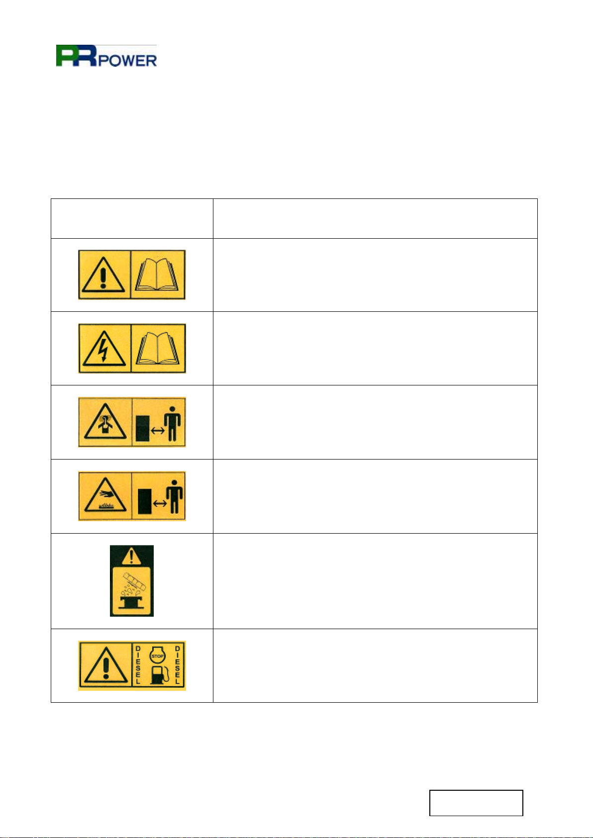
4. SAFETY SIGNS
These signs inform the user of any danger which may cause injury.
Read the precautions and descriptions below:
Danger signs
Description
•Read the instruction handbook before operating the lighting
tower.
•Danger of electric discharges.
•Consult the manual.
•Attention dangerous exhaust fumes.
•Maintain safe distance from the emission zone.
•Danger of burns.
•Don’t touch the exhaust and engine when the lighting tower
is in operation.
•Danger: don’t open when the engine is hot
•Stop the engine before refueling.
•Use diesel fuel only.

PR4000 9mt 4x1000W METAL HALIDE
7
TL073-11-02-03
01-02-2011
•Danger possible spillage of corrosive substances
•Danger possible crush point
Prohibition signs
Description
•It is prohibited to clean, lubricate or regulate moving parts.
•It is prohibited to extinguish fires with water, use fire
extinguishers only.
•It is prohibited to use open flames.
Information signs
Description
•This sign indicates the lifting point for the lighting tower.

PR4000 9mt 4x1000W METAL HALIDE
8
TL073-11-02-03
01-02-2011
5. SAFETY REGULATIONS TO OBSERVE
The manufacturer is not responsible of any damage to equipment or persons, as a result of
operators not adhering to the correct safety regulations.
5.1 BEFORE OPERATING THE MACHINE
•It is advised you wear protective clothes, gloves, safety shoes and ear plugs.
•It is recommended you understand the correct operation of the lighting tower.
•It is recommended that all authorised staff read and understand all warnings and dangers
described in this manual.
•Place barriers 2 meters from the lighting tower to prevent unauthorised staff approaching the
unit.
•Ensure yourself that the lighting tower is not operating and that there are no moving parts.
•Only authorised staff can operate the lighting tower.
•Read the operating instructions and safety warning stickers placed on the lighting tower.
•Connect the unit to the earth through the earth clamp.
•The unit must be connected to the earth using a copper cable with a minimum cross-section of
6 mm².
•Project Rentals is not responsible for any damage caused by failure to earth.
5.2 DURING MAINTENANCE
•Always turn off the lighting tower before any maintenance.
•Extraordinary maintenance must always be carried out by authorized staff.
•Before any maintenance operation on the floodlights, disconnect the power and wait for the
lamps to cool.
•The fluid of battery contains sulphuric acid which is extremely corrosive and harmful to the
skin. Always wear protective gloves and be extremely careful to avoid spillage when pouring
the acid.
•Contact with engine oil can damage your skin. Put on gloves when using engine oil. If you
come in contact with engine oil, wash it off immediately.
5.3 DURING TRANSPORT
•Warning!
Before towing the lighting tower, ensure the engine is switched off to avoid causing damage to
the equipment.
•Only use the correct lifting points as indicated on the tower.
•The lifting point, where present, must be used for the temporary raising and not for suspension
in the air of the equipment for long periods.
•The manufacturer is not responsible for any damage caused by negligence during transport.

PR4000 9mt 4x1000W METAL HALIDE
9
TL073-11-02-03
01-02-2011
6. GENERAL DANGER INFORMATION
6.1 DANGER OF BURNS
•Do not touch hot surfaces with hands e.g. silencers and engine when it is operating.
•Do not touch the floodlights when turned on.
•Always use gloves.
6.2 DANGER OF ELECTROCUTION
•Do not touch electrical parts, it may cause an electric shock.
•Do not touch the electric cables when the lighting tower is operating.
6.3 DANGER OF INJURY
•Do not remove the protective guards placed on the moving parts including, air intakes and fan
belts.
•Do not clean or attempt maintenance on moving parts.
•Use appropriate clothing and safety wear, whilst operating the lighting tower.
6.4 WARNING OF FIRE OR EXPLOSION DURING REFUELING
•Turn off the engine before refueling.
•Do not smoke during refueling.
•Refueling must be conducted in a way that does not cause fuel spillage.
•In the event of fluid spillage during refuelling, dry and clean parts as required.
•Check that there isn’t any spillage of fuel and hoses and hoses are not damaged.
6.5 NOISE
•Use ear plugs or ear muffs for noise protection.
6.6 EXHAUST FUMES
•The exhaust fumes are dangerous for your health. Maintain a safe distance from the emission
zone.
•In the event the lighting tower is used in a closed area, ensure that the exhaust fumes can be
easily dispersed in a safe manner.

PR4000 9mt 4x1000W METAL HALIDE
10
TL073-11-02-03
01-02-2011
7. GENERAL DESCRIPTION OF THE LIGHTING TOWER
The PR4000 has been designed to take into consideration 3 fundamental characteristics:
•Compact design
•Reliability
•Quality manufacturing and design
The construction materials used, guarantee not only extreme strength of the tower, but they are
also synonymous of longer life, in fact these materials are protected against oxidation like rust.
The ability to lower the tower is a key factor for manouverability and transportation. The lighting
tower can be installed and used by a single operator safely. The floodlights used on the lighting
tower, complete with lamps, are made from the world’s leading manufacturers.
8. LIGHTING TOWER NOT IN USE
If the lighting tower is not in operation for a long period (more than one year), we recommend you
keep the oil, fuel and the coolant in the engine to avoid oxidizing effects; we recommend you also
disconnect the battery cables.
When the lighting tower is in operation again, the fluids must be replaced, the battery charged; the
belts and hoses must be checked and a visual inspection of the electrical connections must be
performed.

PR4000 9mt 4x1000W METAL HALIDE
11
TL073-11-02-03
01-02-2011
9. TECHNICAL SPECIFICATION
9.1 GENERATOR
Model Synchronous
Single phase voltage 9 kVA - 240 V
Frequency 50 Hz
Cos ϕ0,8
Insulation class F
Mechanical protection IP 23
9.2 ENGINE
Make/Type Kubota D1105-E
Number of cylinders 3
Displacement 1123 cm3
Power 13,7 HP
Engine speed 1500 r.p.m.
Cooling Water
Fuel Diesel
Starting system Electric
Oil sump capacity 4,5 l
Radiator capacity 4 l
Specific fuel consumption 265 gr/kWh
Fuel tank capacity 116 l
Average operating hours 42 h ~
Noise level DBA at 7 metres 90 Lwa
Battery 12 V - 44 Ah

PR4000 9mt 4x1000W METAL HALIDE
12
TL073-11-02-03
01-02-2011
9.3 HYDRAULIC GEAR BOX
9.3.1 ELECTRICAL MOTOR
Feeding 240 V 50-60 Hz ± 10%
Power 0,55 kW
Poles 4
Duty factor S1
9.3.2 GEAR PUMP
Displacement 1,3 cm3
Maximum pressure 210 bar
Factory setting pressure 180 bar
Emergency action system Manual
9.3.3 UNLOADING SOLENOID VALVE
Coil thermal insulation Class F – VDE0585
Electric connection DIN 43650-A / ISO 4400
Protection degree IP 65
Coil duty cicle ED 100%
Coil voltage 230 V 50-60 Hz ± 10%
9.3.4 HYDRAULIC FLUID
Reservoir capacity 5 l
Fluid type ISO/DIN 6743/4 mineral oil
Fluid viscosity 15-100 mm2 sec – ISO 3448
Fluid temperature -15°C ÷ +80°C
Fluid maximum contamination level Class 10 in accordance with NAS
1638 with filter B 25 > 75
PR4000 9mt 4x1000W METAL HALIDE
13
TL073-11-02-03
01-02-2011
9.4 LIGHTING TOWER
Maximum height 9 mt
Raising Hydraulic
Section 7
Rotation Section 340°
Floodlights group tilt 41°
Electrical coiled cable 11G2,5 mmq
Electrical cable of floodlights H07RN-F
Maximum cable load 3300 kg
Maximum wind stability 110 km/h
Minimum dimension with trailer for
fast towing type B (L x W x H mm) 3417 x 1580 x 2330
Maximum dimension with trailer for
fast towing type B (L x W x H mm) 3417 x 1850 x 9000
Dry weight 1115 kg
9.5 RAISING AND LOWERING ROPE
Rope type AZN625APPCOM
Rope diameter 6 mm
Outer wires diameter 0,4 mm
Weight per meter 0,15 Kg
Costruction 6x(12+(6)+6+1)KF+PP
Type of lay Right hand ordinary lay
Tensile strenght 2160 N/mm²
Strands Compacted
Preformed Yes
Steel wires Carbon
Protection of wire rope Galvanized class B
Minimum breaking load 32,3 kN 3230 Dan 3294 Kg
PR4000 9mt 4x1000W METAL HALIDE
14
TL073-11-02-03
01-02-2011
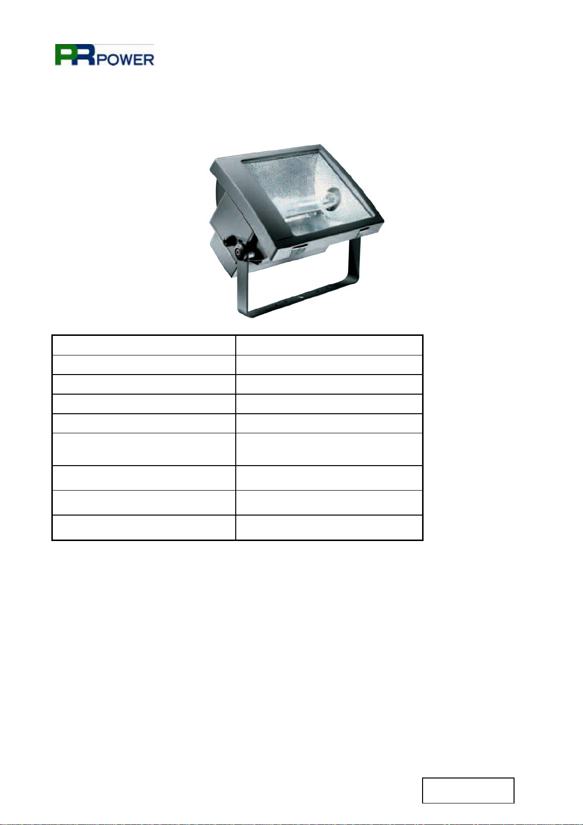
9.6 FLOODLIGHT
Lamp Metal halide
Power 4x1000 W
Degree of protection IP 66
Constructor material of the body Die-cast aluminium
Constructor material of lampholder Ceramic
Reflector Polished and anodized aluminium
99,85
Cable gland Stainless steel
Optical case opening system Stainless steel clips
Dimensions (L x H x D mm) 404 x 260 x 328
The floodlight is provided by tempered glass and silicone seals. Closing hooks and external nuts
and bolts in stainless steel. The casing’s protection against corrosion is ensured by Alodine 1200
chromate treatment and polyester powder coating for outdoors in graphite grey finishing. The
frame is equipped with special drains to prevent water from accumulating.

PR4000 9mt 4x1000W METAL HALIDE
15
TL073-11-02-03
01-02-2011
9.7 LAMP
The metal halide lamps used in the floodlights of the lighting tower allow to a greater lighting
system regarding the traditional halogen lamps and concur to an inferior energetic consumption
beyond to one duration much elevating of near 8000 hours.
The metal halide lamp is a high intensity discharge lamp based on the emission of electromagnetic
cancellation from part of a ionizated gas plasma. The ionization of the gas is obtained for means
of a discharge electrical worker (from which the name) through the gas.
The metal halide lamps derive from the high pressure sodium vapor lamps with the added of
thallium, Indian, dysprosium, holmium, cesium, thulium, which they improve the yield of the colors
of the sodium lamps, and give one temperature to their color much elevated (4000-5600) K. Their
chromatic yield renders them particularly adapted where there is the necessity of having a light
perfectly white. For being ignited they need of apposite igniters and injectors that produce
impulses of tension between 0,75 and 5 kV and for the attainment of the full light flux, in phase of
ignition, they are necessary few minutes.
In case of accidental putting out it is necessary to wait the cooling of the lamp (about 15
minutes) before a new ignition, because of the high tension that would be necessary for a
hot ignition.
PR4000 9mt 4x1000W METAL HALIDE
16
TL073-11-02-03
01-02-2011
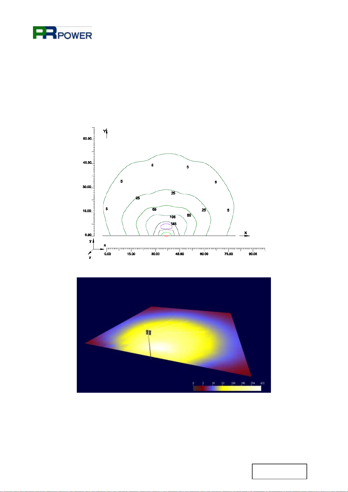
10. LIGHTING FOOT PRINT DIAGRAM
ILLUMINATED AREA
4200 m²

PR4000 9mt 4x1000W METAL HALIDE
17
TL073-11-02-03
01-02-2011
11. IDENTIFICATION OF EXTERNAL COMPONENTS
11.1 LIGHTING TOWER COMPOSITION
Items
Description
1
Floodlights rotation handles
2
Telescopic mast
3
Floodlights
4
Floodlights blocking rotation pin
5
Gas exhaust outlet
6
Radiator cap
7
Engine inspection door with command panel
8
Emergency stop button
9
Plate for transport through forklift
3
2
1
8
6
5
7
9
4

PR4000 9mt 4x1000W METAL HALIDE
18
TL073-11-02-03
01-02-2011
Items
Description
10
Fixed stabilizers
11
Air inlet grill
12
Lockable battery insulator switch
13
Air outlet grill
14
Lifting hook
15
Extractable stabilizers
16
Trailer for fast or slow towing (on the ground of model)
17
Door engine inspection
13
14
16
15
11
10
17
12

PR4000 9mt 4x1000W METAL HALIDE
19
TL073-11-02-03
01-02-2011
11.2 EMERGENCY STOP BUTTON AND EARTH CLAMP
Items Description
18 Earth clamp connection
19 Emergency stop button
Connect the unit to the earth, through the clamp (18).
The unit must be connected to earth using a copper cable with a minimum cross-section of 6 mm².
The manufacturer is not responsible for any damage caused by failure of the earthing.
Make sure that the emergency stop button (19) is rearmed. If it doesn’t, turn the grip handle in
clockwise direction.
In emergency case it is possible to stop the generating set by pressing the stop button (19).
18 19

PR4000 9mt 4x1000W METAL HALIDE
20
TL073-11-02-03
01-02-2011
11.3 BATTERY SWITCH
Items Description
20 Lockable battery insulator switch
The machine is supplied with the battery switch disconnect (20).
Connect the battery switch (20).
If the machine has to be stopped for a long period, we suggest to disconnect the battery switch
(20).
20
Table of contents
Other PR POWER Lighting Equipment manuals


