PR POWER PR8000 User manual


PR8000 9mt 4x2000W METAL HALIDE
2
TL116-11-00-03
01-04-2011
INDEX
1. CE MARK............................................................................................................................4
2. MAINTENANCE & OPERATION.........................................................................................4
3. GENERAL INFORMATION.................................................................................................5
3.1 EQUIPMENT DOCUMENTATION FOR THE LIGHTING TOWER......................................5
4. SAFETY SIGNS..................................................................................................................6
5. SAFETY REGULATIONS TO OBSERVE ...........................................................................8
5.1 BEFORE OPERATING THE MACHINE.............................................................................8
5.2 DURING MAINTENANCE..................................................................................................8
5.3 DURING TRANSPORT......................................................................................................8
6. GENERAL DANGER INFORMATION.................................................................................9
6.1 DANGER OF BURNS ........................................................................................................9
6.2 DANGER OF ELECTROCUTION ......................................................................................9
6.3 DANGER OF INJURY........................................................................................................9
6.4 WARNING OF FIRE OR EXPLOSION DURING REFUELING............................................9
6.5 NOISE...............................................................................................................................9
6.6 EXHAUST FUMES ............................................................................................................9
7. GENERAL DESCRIPTION OF THE LIGHTING TOWER..................................................10
8. LIGHTING TOWER NOT IN USE......................................................................................10
9. TECHNICAL SPECIFICATION .........................................................................................11
9.1 GENERATOR..................................................................................................................11
9.2 ENGINE...........................................................................................................................11
9.3 HYDRAULIC GEAR BOX.................................................................................................12
9.3.1 ELECTRICAL MOTOR ..............................................................................................12
9.3.2 GEAR PUMP.............................................................................................................12
9.3.3 HYDRAULIC FLUID...................................................................................................12
9.4 LIGHTING TOWER..........................................................................................................13
9.5 RAISING ANDLOWERING CABLE.................................................................................13
9.6 FLOODLIGHT..................................................................................................................14
9.7 LAMP...............................................................................................................................15
10. IDENTIFICATION OF EXTERNAL COMPONENTS..........................................................16
10.1 LIGHTING TOWER BREAKDOWN..................................................................................16
10.2 BATTERY AND STARTING SWITCH ..............................................................................19
10.3 RADIATOR CAP PROTECTION PLATE..........................................................................20
11. IDENTIFICATION OF INNER COMPONENTS..................................................................21
11.1 UPPER CONTROLS DESCRIPTION...............................................................................21
11.2 LOWER CONTROLS DESCRIPTION..............................................................................22
11.3 CONTROLS LEVERS......................................................................................................23
11.4 HYDRAULIC GEAR BOX.................................................................................................24
11.4.1 LOWERING HANDLE BAR BRACKET IN CASE OF EMERGENCY .........................25
11.5 BATTERY........................................................................................................................26
11.6 FUEL TANK.....................................................................................................................27
11.7 ENGINE OIL CAP............................................................................................................28
11.8 CHANGE ENGINE OIL ....................................................................................................29

PR8000 9mt 4x2000W METAL HALIDE
3
TL116-11-00-03
01-04-2011
12. OPERATING INSTRUCTIONS..........................................................................................30
12.1 LIGHTING TOWER POSITIONING..................................................................................30
12.2 CONNECTING OFTHE BATTERY..................................................................................30
12.3 CONNECTING OFTHE STARTER MOTOR....................................................................30
12.4 EARTHING......................................................................................................................30
12.5 PRELIMINARY CHECKS.................................................................................................30
12.6 ENGINE STARTING........................................................................................................30
12.7 RUNNING IN ...................................................................................................................31
12.8 USE OF LIGHTING TOWER............................................................................................31
12.9 GENERATOR ALARMS...................................................................................................31
12.10 REMARKS.......................................................................................................................32
12.11 USE OF THE LIGHTING TOWER....................................................................................33
12.12 STOPPING THE ENGINE................................................................................................37
13. LIGHTING TOWER MAINTENANCE................................................................................38
13.1 LUBRICATION OF THE ROLLERS..................................................................................38
13.2 LUBRICATION OF MAST SECTIONS .............................................................................38
13.3 LUBRICATION OF STABILISERS...................................................................................38
13.4 CHECK HYDRAULIC CYLINDER....................................................................................38
13.5 CHECK STEEL CABLES.................................................................................................38
13.6 CHECK OF HYDRAULIC CONNECTIONS......................................................................38
14. TROUBLESHOOTING GUIDE..........................................................................................39
14.1 MAIN ISSUES..................................................................................................................39
15. REPLACE THE LAMP AND LENSES ..............................................................................45
16. SPARE PARTS.................................................................................................................46
16.1 UPPER COMMAND PANEL SPARE PARTS LIST...........................................................46
16.2 LOWER COMMAND PANEL SPARE PARTS LIST..........................................................47
16.3 CONTROL PANEL DOOR SPARE PARTS LIST..............................................................48
16.4 CENTRAL PANEL AND RADIATOR SUPPORT SPARE PARTS LIST.............................49
16.5 SPARE PARTS LIST HYDRAULIC PARTS......................................................................50
16.6 SPARE PARTS LIST FOR SOLENOID AND ENGINE SUPPORT....................................51
16.7 SPARE PARTS LIST FOR FRAME..................................................................................52
16.8 SPARE PARTS LIST FOR CANOPY ...............................................................................54
16.9 SPARE PARTS LIST FOR TELESCOPIC MAST .............................................................56
16.10 LAMPS SPARE PARTS LIST...........................................................................................58
16.11 SPARE PARTS LIST FOR ALTERNATOR.......................................................................60
16.12 TRAILER FOR FAST TOWING HEIGHT ADJUSTABLE SPARE PARTS LIST.................62
16.13 SPARE PARTS LIST FOR STICKERS FOR LIGHTING TOWER.....................................63
17. WIRING DIAGRAM...........................................................................................................66

PR8000 9mt 4x2000W METAL HALIDE
4
TL116-11-00-03
01-04-2011
1. CE MARK
The CE mark (European Community) certifies that the product complies with essential safety
requirements provided by the applicable Community Directives.
2. MAINTENANCE & OPERATION
Dear Customer, many thanks for the purchase of our product. Contained in this manual is all the
necessary information for use and the general maintenance of the lighting tower.
The responsibility for the correct operation of the lighting tower depends on the operator.
Before installation and operation of the lighting tower, read the manual carefully. If this manual is
not clear or comprehensible, contact PR Power Australia wide on:
1300 399 499
All the specifications and pictures in this manual are subject to modifications without prior
notice.

PR8000 9mt 4x2000W METAL HALIDE
5
TL116-11-00-03
01-04-2011
3. GENERAL INFORMATION
The lighting tower is designed, produced and tested to meet the European Standards and to
reduce the electrical risks in compliance with the laws.
3.1 EQUIPMENT DOCUMENTATION FOR THE LIGHTING TOWER
The manufacturer declines responsibility from any unauthorised modification of the
product.
Together with this manual we are supplying the following documents:
•Engine use and maintenance manual.
•Instruction manual and use for the lighting tower (this manual).
•Alternator use and maintenance manual.
•Check list for the lighting tower.
•CE declaration of conformity. Warranty certificate.
•Pre-delivery check report.

PR8000 9mt 4x2000W METAL HALIDE
6
TL116-11-00-03
01-04-2011
4. SAFETY SIGNS
These signs inform the user of any danger which may cause injury.
Read the precautions and descriptions below:
Danger signs
Description
•Read the instruction handbook before operating the lighting
tower.
•Danger of electric discharges.
•Consult the manual.
•Attention dangerous exhaust fumes.
•Maintain safe distance from the emission zone.
•Danger of burns.
•Don’t touch the exhaust and engine when the lighting tower
is in operation.
•Danger: don’t open when the engine is hot
•Stop the engine before refueling.
•Use diesel fuel only.

PR8000 9mt 4x2000W METAL HALIDE
7
TL116-11-00-03
01-04-2011
•Danger possible spillage of corrosive substances
•Danger possible crush point
Prohibition signs
Description
•It is prohibited to clean, lubricate or regulate moving parts.
•It is prohibited to extinguish fires with water, use fire
extinguishers only.
•It is prohibited to use open flames.
Information signs
Description
•This sign indicates the lifting point for the lighting tower.

PR8000 9mt 4x2000W METAL HALIDE
8
TL116-11-00-03
01-04-2011
5. SAFETY REGULATIONS TO OBSERVE
The manufacturer is not responsible of any damage to equipment or persons, as a result of
operators not adhering to the correct safety regulations.
5.1 BEFORE OPERATING THE MACHINE
•It is advised you wear protective clothes, gloves, safety shoes and ear plugs.
•It is recommended you understand the correct operation of the lighting tower.
•It is recommended that all authorised staff read and understand all warnings and dangers
described in this manual.
•Place barriers 2 meters from the lighting tower to prevent unauthorised staff approaching the
unit.
•Ensure yourself that the lighting tower is not operating and that there are no moving parts.
•Only authorised staff can operate the lighting tower.
•Read the operating instructions and safety warning stickers placed on the lighting tower.
•Connect the unit to the earth through the earth clamp.
•The unit must be connected to the earth using a copper cable with a minimum cross-section of
6 mm².
•PR POWER is not responsible for any damage caused by failure to earth.
5.2 DURING MAINTENANCE
•Always turn off the lighting tower before any maintenance.
•Extraordinary maintenance must always be carried out by authorized staff.
•Before any maintenance operation on the floodlights, disconnect the power and wait for the
lamps to cool.
•The fluid of battery contains sulphuric acid which is extremely corrosive and harmful to the skin.
Always wear protective gloves and be extremely careful to avoid spillage when pouring the
acid.
•Contact with engine oil can damage your skin. Put on gloves when using engine oil. If you
come in contact with engine oil, wash it off immediately.
5.3 DURING TRANSPORT
•Warning!
Before towing the lighting tower, ensure the engine is switched off to avoid causing damage to
the equipment.
•Only use the correct lifting points as indicated on the tower.
•The lifting point, where present, must be used for the temporary raising and not for suspension
in the air of the equipment for long periods.
•The manufacturer is not responsible for any damage caused by negligence during transport.

PR8000 9mt 4x2000W METAL HALIDE
9
TL116-11-00-03
01-04-2011
6. GENERAL DANGER INFORMATION
6.1 DANGER OF BURNS
•Do not touch hot surfaces with hands e.g. silencers and engine when it is operating.
•Do not touch the floodlights when turned on.
•Always use gloves.
6.2 DANGER OF ELECTROCUTION
•Do not touch electrical parts, it may cause an electric shock.
•Do not touch the electric cables when the lighting tower is operating.
6.3 DANGER OF INJURY
•Do not remove the protective guards placed on the moving parts including, air intakes and fan
belts.
•Do not clean or attempt maintenance on moving parts.
•Use appropriate clothing and safety wear, whilst operating the lighting tower.
6.4 WARNING OF FIRE OR EXPLOSION DURING REFUELING
•Turn off the engine before refueling.
•Do not smoke during refueling.
•Refueling must be conducted in a way that does not cause fuel spillage.
•In the event of fluid spillage during refuelling, dry and clean parts as required.
•Check that there isn’t any spillage of fuel and hoses and hoses are not damaged.
6.5 NOISE
•Use ear plugs or ear muffs for noise protection.
6.6 EXHAUST FUMES
•The exhaust fumes are dangerous for your health. Maintain a safe distance from the emission
zone.
•In the event the lighting tower is used in a closed area, ensure that the exhaust fumes can be
easily dispersed in a safe manner.

PR8000 9mt 4x2000W METAL HALIDE
10
TL116-11-00-03
01-04-2011
7. GENERAL DESCRIPTION OF THE LIGHTING TOWER
The PR8000 has been designed to take into consideration 3 fundamental characteristics:
•Compact design
•Reliability
•Quality manufacturing and design
The construction materials used, guarantee not only extreme strength of the tower, but they are
also synonymous of longer life, in fact these materials are protected against oxidation like rust.
The ability to lower the tower is a key factor for manouverability and transportation. The lighting
tower can be installed and used by a single operator safely. The floodlights used on the lighting
tower, complete with lamps, are made from the world’s leading manufacturers.
8. LIGHTING TOWER NOT IN USE
If the lighting tower is not in operation for a long period (more than one year), we recommend you
keep the oil, fuel and the coolant in the engine to avoid oxidizing effects; we recommend you also
disconnect the battery cables.
When the lighting tower is in operation again, the fluids must be replaced, the battery charged; the
belts and hoses must be checked and a visual inspection of the electrical connections must be
performed.

PR8000 9mt 4x2000W METAL HALIDE
11
TL116-11-00-03
01-04-2011
9. TECHNICAL SPECIFICATION
9.1 GENERATOR
Model Synchronous
Three phase voltage 20 kVA - 415 V
Frequency 50 Hz
Cos ϕ0,8
Insulation class F
Mechanical protection IP 23
9.2 ENGINE
Make/Type Kubota D1703-E2BG
Number of cylinders 3
Displacement 1647 cm3
Power 17,2 HP (SAE NET Continuous)
19,4 HP (SAE Standby)
Engine speed 1500 r.p.m.
Cooling Water
Fuel Diesel
Starting system Electric
Oil sump capacity 7,0 l
Radiator capacity 5,5 l
Specific fuel consumption 230 gr/kWh
Fuel tank capacity 180 l
Average operating hours 80 hrs approx
Noise level DBA at 7 metres 90 Lwa
Battery 12 V - 80 Ah

PR8000 9mt 4x2000W METAL HALIDE
12
TL116-11-00-03
01-04-2011
9.3 HYDRAULIC GEAR BOX
9.3.1 ELECTRICAL MOTOR
Feeding 400 V 50-60 Hz ± 10%
Power 2 HP
Poles 4
Mechanical protection IP55
9.3.2 GEAR PUMP
Displacement 3,2 cm3
Maximum pressure 210 bar
Factory setting pressure 180 bar
Emergency action system Manual
9.3.3 HYDRAULIC FLUID
Reservoir capacity 20 l
Fluid type ISO/DIN 6743/4 mineral oil
Fluid viscosity 15-100 mm2 sec – ISO 3448
Fluid temperature -15°C ÷ +80°C
Fluid maximum contamination level Class 10 in accordance with NAS
1638 with filter B 25 > 75
PR8000 9mt 4x2000W METAL HALIDE
13
TL116-11-00-03
01-04-2011
9.4 LIGHTING TOWER
Maximum height 9 mt
Raising Hydraulic
Section 7
Rotation Section 360°
Floodlights group tilt 41°
Electrical coiled cable 11G2,5 mmq
Electrical cable of floodlights H07RN-F
Maximum cable load 3300 kg
Maximum wind stability 110 km/h
Minimum dimension with trailer for
fast towing type B (L x W x H mm) 3630 x 1690 x 2580
Maximum dimension with trailer for
fast towing type B (L x W x H mm) 3777 x 2300 x 9000
Dry weight 1710 Kg
9.5 RAISING AND LOWERING CABLE
Cable type AZN625APPCOM
Cable diameter 6 mm
Outer wires diameter 0,4 mm
Weight per meter 0,15 Kg
Construction 6x(12+(6)+6+1)KF+PP
Type of lay Right hand ordinary lay
Tensile strength 2160 N/mm²
Strands Compacted
Preformed Yes
Steel wires Carbon
Protection of wire rope Galvanized class B
Minimum breaking load 32,3 kN 3230 Dan 3294 Kg
PR8000 9mt 4x2000W METAL HALIDE
14
TL116-11-00-03
01-04-2011
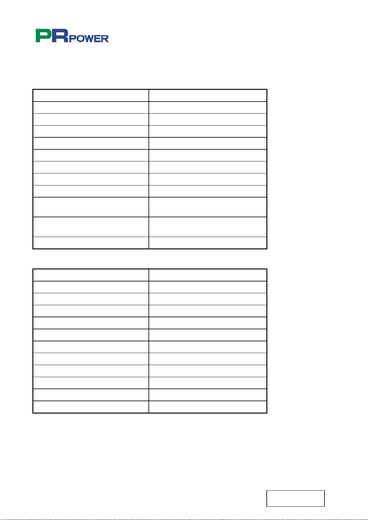
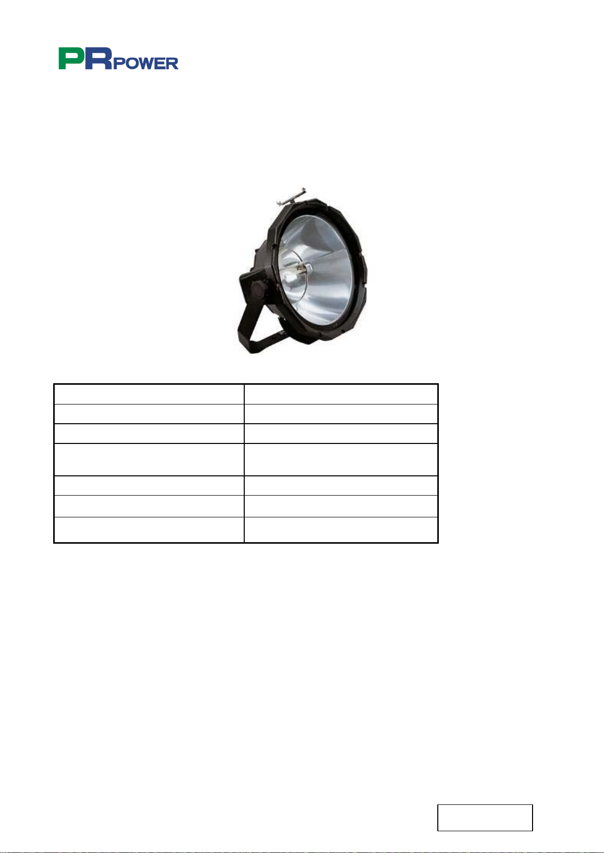
9.6 FLOODLIGHT
Lamp Metal halide
Power 4x2000 W
Degree of protection IP 65
Constructor material of the body Die-cast primary aluminium UNI
5076 alloy
Constructor material of lampholder Ceramic
Lampholder K12s-7 base
Dimensions (L x H x D mm) 535 x 540 x 250
The floodlight is protected by tempered glass and silicone seals. External bolts are stainless steel.

PR8000 9mt 4x2000W METAL HALIDE
15
TL116-11-00-03
01-04-2011
9.7 LAMP
The metal halide lamps used in the floodlights of the lighting tower provide a brighter lighting
system than traditional halogen lamps.
The metal halide lamp is a high intensity discharge lamp.
In the event the lights are accidentally switched off, you must wait for the lamps to cool
(about 15 minutes) before re-igniting.

PR8000 9mt 4x2000W METAL HALIDE
16
TL116-11-00-03
01-04-2011
10. IDENTIFICATION OF EXTERNAL COMPONENTS
10.1 LIGHTING TOWER BREAKDOWN
Items
Description
1
Control panel door
2
Engine inspection door
3
Lockable battery and starting key insulator switch
4
Hydraulic Controls
5
Telescopic mast
6
Floodlights
7
Floodlights rotation handles
8
Emergency stop button
9
Heavy DutyTrailer for fast or slow towing
3
2
1
7
6
8
5
4
9

PR8000 9mt 4x2000W METAL HALIDE
17
TL116-11-00-03
01-04-2011
12
13
14
15
Items
Description
10
Mast rotation locking pin
11
Lifting hook
12
Gas exhaust outlet
13
Radiator cap
14
Air outlet grill
15
Hydraulic stabilizers
16
Door engine inspection
17
Door for papers
10
11
16
17

PR8000 9mt 4x2000W METAL HALIDE
18
TL116-11-00-03
01-04-2011
Items Description
18 Emergency stop button
19 Earth clamp connection
Connect the unit to the earth, through the clamp (19).
The unit must be connected to earth using a copper cable with a minimum cross-section of 6 mm².
PR POWER is not responsible for any damage caused as a result of failing to earth.
Make sure that the emergency stop button (18) is armed. If not, turn the grip handle in clockwise
direction. In an emergency it is possible to stop the generating set by pressing the stop button (18).
18
19

PR8000 9mt 4x2000W METAL HALIDE
19
TL116-11-00-03
01-04-2011
10.2 BATTERY AND STARTING SWITCH
Items Description
20 Lockable battery isolator switch
21 Lockable starting key isolator switch
The machine is supplied with the battery switch disconnected (20).
Connect the battery switch (20).
If the lighting tower is not operating for long periods, we recommend you disconnect the battery
switch (20).
The machine is supplied with the starting key switch disconnected (21).
Connect the starting key switch (21).
20
21

PR8000 9mt 4x2000W METAL HALIDE
20
TL116-11-00-03
01-04-2011
22
10.3 RADIATOR CAP PROTECTION PLATE
Items Description
22 Radiator cap protection plate
To fill up and replace coolant, firstly lift the protection plate of the radiator cap and then unscrew
the radiator cap.
The coolant will last for one day if filled all the way up before operation start; therefore check the
coolant level before every operation.
In order to avoid personal injury do not remove the radiator cap when the engine is running. When
the engine is idle, loosen the cap slightly to relieve any excess of pressure before removing cap
completely.
If the lighting tower is not operating for a long period of time (more than one year), we recommend
you keep the coolant in the radiator in order to avoid oxidizing effects.
Table of contents
Other PR POWER Lighting Equipment manuals

Popular Lighting Equipment manuals by other brands


Commercial Electric
Commercial Electric 1004 105 594 Use and care guide

Bestway
Bestway Flowclear 58216 owner's manual

Solid Apollo
Solid Apollo Neon LED user manual

kim lighting
kim lighting Hubbell LIGHTVAULT LTV30 installation instructions

EuroLite
EuroLite ML-575 MSR user manual

MA
MA LIGHTCOMMANDER II 48/6 user manual

Flight Light
Flight Light L810 Installation and maintenance manual

Federal Signal Corporation
Federal Signal Corporation 121X Series Installation and service instructions

Carmanah
Carmanah R247 owner's manual

Inter-fab
Inter-fab EDGESTONE SLIDE ROCK installation guide

Loevschall
Loevschall 14-320D-IP44 Instructions for use

Lightolier
Lightolier Lytecaster 1104F13ES specification