PRACHT ALPHA User manual

State: März 2023
(NRG1006)

1
NOTES ON THIS DOCUMENT ............................................................................................................Fehler! Textmarke nicht definiert.
SAFETY, INSTALLATION AND USE.......................................................................................................Fehler! Textmarke nicht definiert.
OTHER USE INSTRUCTIONS..........................................................................................................Fehler! Textmarke nicht definiert.
SCOPE OF DELIVERY ..........................................................................................................................Fehler! Textmarke nicht definiert.
TECHNICAL DATA...............................................................................................................................Fehler! Textmarke nicht definiert.
ASSEMBLY..........................................................................................................................................Fehler! Textmarke nicht definiert.
REQUIREMENTS...........................................................................................................................Fehler! Textmarke nicht definiert.
WALL MOUNTING........................................................................................................................Fehler! Textmarke nicht definiert.
ELECTRICAL CONNECTION.................................................................................................................Fehler! Textmarke nicht definiert.
CONNECTION TO THE MAINS......................................................................................................Fehler! Textmarke nicht definiert.
WIRING OF THE RFID MODULE....................................................................................................Fehler! Textmarke nicht definiert.
SETTING THE MAXIMUM CURRENT.............................................................................................Fehler! Textmarke nicht definiert.
VALUES FOR ALPHA NRG1002 (MAX. 11KW PER VEHICLE)..........................................................Fehler! Textmarke nicht definiert.
VALUES FOR ALPHA NRG1012 (MAX. 22KW PER VEHICLE)..........................................................Fehler! Textmarke nicht definiert.
INITIAL COMMISSIONING.................................................................................................................Fehler! Textmarke nicht definiert.
OPERATION........................................................................................................................................Fehler! Textmarke nicht definiert.
LED DISPLAY .................................................................................................................................Fehler! Textmarke nicht definiert.
RFID CARD TEACH-IN....................................................................................................................Fehler! Textmarke nicht definiert.
RFID CARD DELETION...................................................................................................................Fehler! Textmarke nicht definiert.
ACTIVATION OF THE WALLBOX.....................................................................................................Fehler! Textmarke nicht definiert.
LOAD.............................................................................................................................................Fehler! Textmarke nicht definiert.
SEQUENTIAL LOADING.................................................................................................................Fehler! Textmarke nicht definiert.
RESTARTING THE BOX ..................................................................................................................Fehler! Textmarke nicht definiert.
INTERFACE RS 485.............................................................................................................................Fehler! Textmarke nicht definiert.
MAINTENANCE AND CLEANING........................................................................................................Fehler! Textmarke nicht definiert.
ENVIRONMENT..................................................................................................................................Fehler! Textmarke nicht definiert.
TROUBLESHOOTING..........................................................................................................................Fehler! Textmarke nicht definiert.
CONTACT ADDRESS ...........................................................................................................................Fehler! Textmarke nicht definiert.

2
Before installing and using the wallbox, the instructions must be read and understood in full by the installer and each user.
Please keep the manual for the entire service life of the wallbox in order to be able to access it later.
Also observe the operating instructions for your electric vehicle.
The wallbox is only suitable for use in private and semi-public areas (e.g. company parking lots).
The wallbox must not be installed in areas with an explosive atmosphere (EX area) or where flammable liquids or objects are
stored.
The wallbox is only suitable for stationary installation. Minimumdistances of 50cm to all neighboring objects must bemaintained.
Installation in a closed box is not permitted. Likewise, the wallbox must not be installed in areas at risk of flooding.
The wallbox may only be installed and put into operation for the first time by a trained electrician.
The electrical connection must be made in accordance with nationally applicable standards, as well as other national and
international regulations regarding accident prevention and personal protection, as well as fire protection.
The wallbox may only be connected to and operated on TT, TN-C and TN-C-S networks. Operation on an IT network is not
permitted.
Work on the wallbox may only be carried out when it is de-energized. There is a risk of fatal electric shock due to the
components inside the box!
Modifications or conversions to the wallbox are not permitted and will result in the loss of any warranty and guarantee claims
against the manufacturer.
The box and all associated components may only be used for their intended purpose. The manufacturer assumes no liability for
personal injury or property damage resulting from improper use.
Defective or damaged wallboxes must not be put into operation. In this case, contact your installer.
Check the function of the RCD switch regularly in accordance with national regulations.

3
•Vessels containing liquids must not be placed on the charging station
•Kinking or running over of the charging cable must be avoided
•The charging cable must be wound up on the device provided for this purpose when the charging station is not in use
•Fix the charging coupler in the charging coupler receptacle provided when not in use.
•Before using the charging coupler, check it visually for damage or dirt on the contacts.
•The charging coupler must not be disconnected from the vehicle during the charging process
•The insertion of objects into the charging coupler is prohibited
•Do not wash the vehicle with a garden hose or high-pressure cleaner when the charging coupling is plugged in, in order
to prevent water from entering the charging coupling or the connecting device of the vehicle.
•The vehicle must be parked at a suitable distance from the charging station to ensure that the charging cable can be
plugged in without tensile stress
•Avoid direct sunlight
•Do not open charging station mounted outdoors during rain or snowfall
•The charging cable must not be connected to extension cords or adapter cables
•Do not allow children to play unsupervised in the vicinity of the charging station
•The charging station must always be closed during operation
•The key for opening the charging station should be kept in a place to which unauthorized persons have no access
•For persons with a pacemaker or defibrillator, despite compliance with all European directives and standards on
electromagnetic compatibility, no statement can be made regarding the suitability of use, maintenance or repair work
of the charging station. Please contact the manufacturer of the defibrillator or pacemaker for further information.
•Improper use can cause serious injury or death, as well as destroy the vehicle or the charging station
•Wallbox ALPHA DUO with RFID module and RS 485 interface
•Key
•Jumper, pre-assembled
•Instruction manual
•Drilling template
•Fastening material, consisting of:
1x mounting lug left
1x mounting bracket right
8x self-tapping screws for mounting straps
•2 pieces RFID card (more cards available - NRG9003)
Check the scope of delivery for completeness.
4
ALPHA –NRG1006
Charging power mode 3 [kW] per
output
Charging power mode 3 [kW] total
3.7 (1-phase) / 11 (3-phase)
7.4 (1-phase) / 22 (3-phase)
Nominal voltage UN [V] 50Hz
230 (1-phase) / 400 (3-phase)
max. line protection [A]
20
Residual current
protection/disconnecting device
30
AC [mA]
6
max. current consumption [A]
(adjustable)
10, 13, 16, 20
max. charging current [A] per vehicle
16
Protection type
IP 65
Protection class
I
Impact resistance box
IK08
Number of charging ports
2
Charging port/coupling
Typ 2
Charging cable length [m]
5,5
Mounting location
Indoor, protected outdoor, no direct sunlight
Mounting type
Wall mounting, column mounting (optional)
Ambient temperature
-20°C to +40°C for connected load < 11kW
-25°C to +35°C with connected load > 11kW
Altitude
max. 2000m a.s.l.
Relative humidity [%]
max. 95 (non-condensing)
Dimensions [mm] (W x H x D)
299 x 425 x 180 (without coupling)
299 x 425 x 380 (with coupling)
Material
ABS, Aluminum
Weight [kg]
11
optionally available
NRG9000 - Stand with roof
NRG9001 - Roof for mounting in unprotected outdoor area
NRG9003 - RFID cards
NRG9004 - Wall cable holder
5
The wallbox may only be installed by a trained electrician.
Before installation, the device must be thoroughly checked for damage.
The wallbox is only suitable for vertical installation.
The box may be mounted indoors or in protected outdoor areas, such as under canopies. The ambient temperature at the
installation site must be in the range of -20°C to +40°C. The wallbox must be mounted away from easily flammable parts.
Sufficient ventilation must be ensured during operation. The mounting location must be selected so that the connected charging
cables cannot come into contact with water. To prevent the ingress of water, the proper fit of the cover and the tight fit of the
cable glands must be checked after installation.
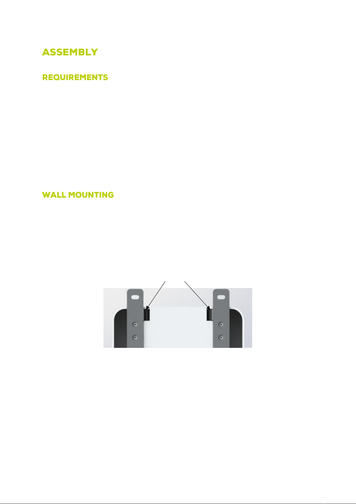
1. The enclosed mounting plates (left/right) are to be mounted on the back of the wallbox with four self-tapping screws
each. Make sure that the beveled tabs are oriented towards the center of the housing (cf. Figure 1).
2. The drilling distances for wall mounting are to be transferred to the wall with the aid of the enclosed drilling template.
3. Drill holes in the wall.
4. Insert four dowels (not included in the scope of delivery) according to the wall condition.
5. Screw the two lower screws into the dowels and place the wallbox on the screws using the screw holes.
6. Screw the upper screws into the dowels, align the wallbox and finally fasten it using the total of four screws.
Figure 1 Arrangement of the mounting plates
The next step is the electrical connection of the wallbox.
Straps
6
The supply line of the wallbox must be disconnected from the power supply during installation work.
The supply line must be correctly fused.
1. Pull the supply line into the box
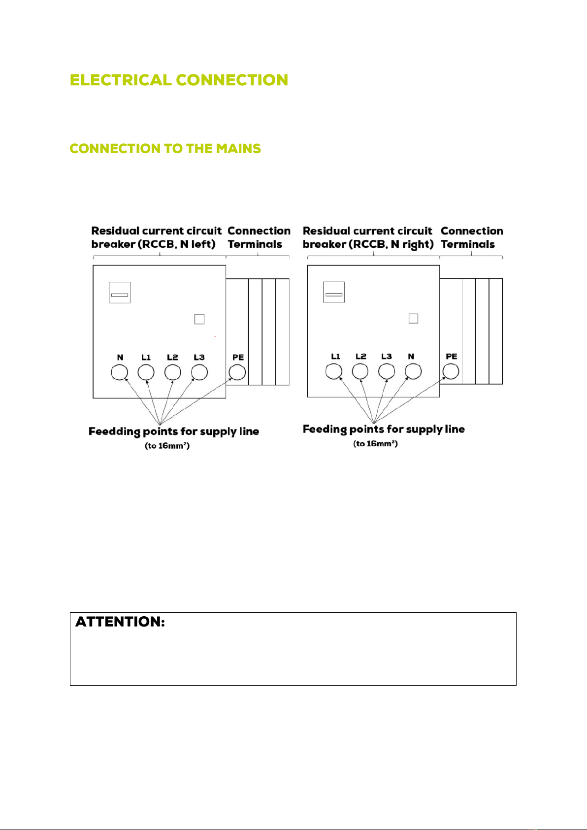
2. Connect the supply line as shown in Figure 2 and then relieve the strain and seal it using the cable gland.
Figure 2 Connection position of the supply line
Check the electrical connection and voltages using a measuring device.
Also make sure that neutral (blue) and ground (PE, yellow/green) are connected correctly.
The sequence of L1, L2, L3, N may differ depending on the type. Please observe the imprint next to the connection terminals.
Switch off the RCD during insulation resistance tests (according to DIN VDE 0100-600) to avoid
damage to the electronics!
7
When using RS485, a double line with a characteristic impedance of 120 Ohm must be used. Since this is a data bus, it must be
terminated with a resistor at the end or beginning. This can be done with the resistor pre-mounted in the interface or with the
termination functions of other Modbus accessories. When using our PCC, it must always be mounted at the beginning or end of
the bus as it has an integrated termination resistor. The GND connection must be carried on a separate wire (or pair of wires) in
the cable to avoid interference effects.
Figure 3 Modbus cable connection
It should be noted that the loading speed depends mainly on two factors:
1. amount of the maximum power output of the wallbox.
2. maximum charging power of the electric vehicle
Preferably, the wallbox should be connected with three phases.
Before commissioning, the maximum current that the wallbox draws via the supply line must be set using the enclosed jumper
on the control board.
When setting the maximum current, it must not be higher than the fuse or the cable cross-section and the length of the supply
line allow.
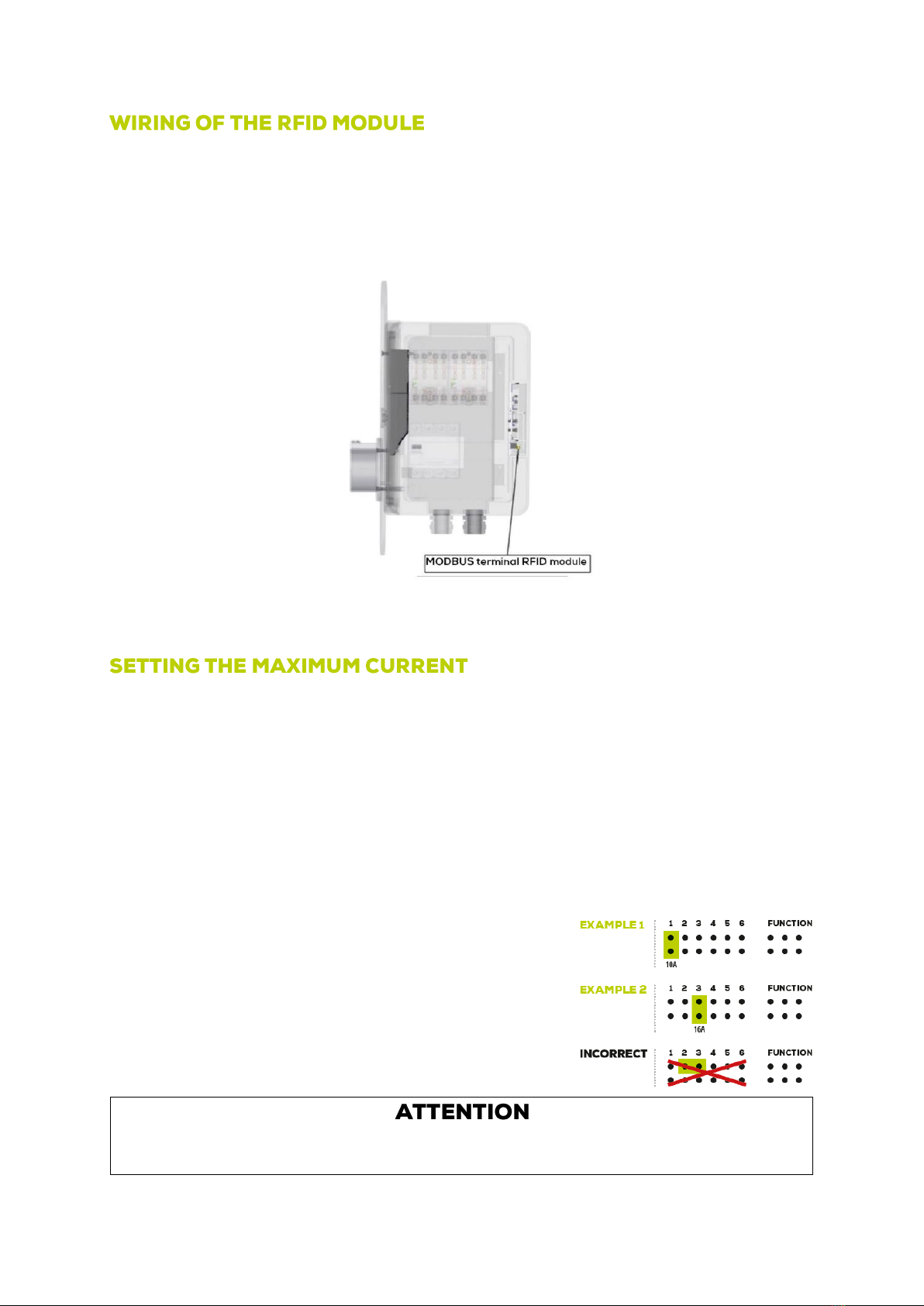
The setting is made by plugging the jumper into the corresponding position on the
control unit. The slots on the control unit can be found by means of the inscription
"I max". The assignment of the slots is shown in the following tables:
Slot 5 to 8 are not to be used!

8
By setting an additional jumper to FUNCTION 1, simultaneous loading of the vehicles is prevented. Loading now takes place one
after the other. The vehicle that first makes the request to load is served first. The second vehicle can only be charged after the
charging request has been dropped.
1 Car 1 Car 1 Car
(1Ph supply line, 1Ph
car)
(3Ph supply line,
2Ph car)
(3Ph supply line,
3Ph car)
1 10 A 1,5 mm² 2,3 kW 2,3 kW 0,0 kW 4,6 kW 4,6 kW 0,0 kW 6,9 kW 6,9 kW 0,0 kW
2 13 A 1,5 mm² 3,0 kW 1,6 kW 1,4 kW 6,0 kW 3,2 kW 2,8 kW 9,0 kW 4,8 kW 4,2 kW
3 16 A 2,5 mm² 3,7 kW 1,8 kW 1,8 kW 7,4 kW 3,7 kW 3,7 kW 11,0 kW 5,5 kW 5,5 kW
4 20 A 4,0 mm² 3,7 kW 2,3 kW 2,3 kW 7,4 kW 4,6 kW 4,6 kW 11,0 kW 6,9 kW 6,9 kW
*After the end of the charging process, the power at the other connection point corresponds to the charging power with only one vehicle.
Nominal values with tolerance +-10%
(1Ph supply line,
1Ph car)
(3Ph supply line,
2Ph car)
(3Ph supply line,
3Ph car)
Position connector
(Jumper)
Current raiting
Min. cross section
supply line
1-PHASE LOADING
2-PHASE LOADING
3-PHASE LOADING
2 Car
2 Car
2 Car
Before commissioning, check that the jumper is seated correctly.
No settings are required to divide the charging current between two vehicles. The charging current is regulated by the controller.
Due to increased cable length of the supply line, it may also be necessary to compensate for the resulting voltage drop by using
a larger cable cross-section.
1. Before commissioning the wallbox, all vehicles must be disconnected from the system.
2. Turn on the fuse in your house power box.
3. Turn on the RCD switch located in the box.
The microcontroller now starts automatically. Within 2 seconds, the box reports the preselected settings by flashing all
LEDs. The number of flashes indicates the presetting. For example, if the LEDs flash ten times, the presetting is 10A.
After successful commissioning, the red LED on the control board goes out. The green LED, on the other hand, lights up
permanently.
4. The door must be locked with the enclosed triangular key.
If the red LED remains permanently lit, there is a fault in the system.
In this case, the wallbox must not be put into operation.
9
This charging station is suitable for electrically charging one or two vehicles with type 2 charging couplings.
By programming an RFID card (see "Programming RFID cards"), charging is only possible for authorized persons. If no RFID card
is programmed, the wallbox is freely accessible.
Pay attention to your safety when operating inside the wallbox and do not touch any live components. Also observe the
operating instructions for your electric vehicle.
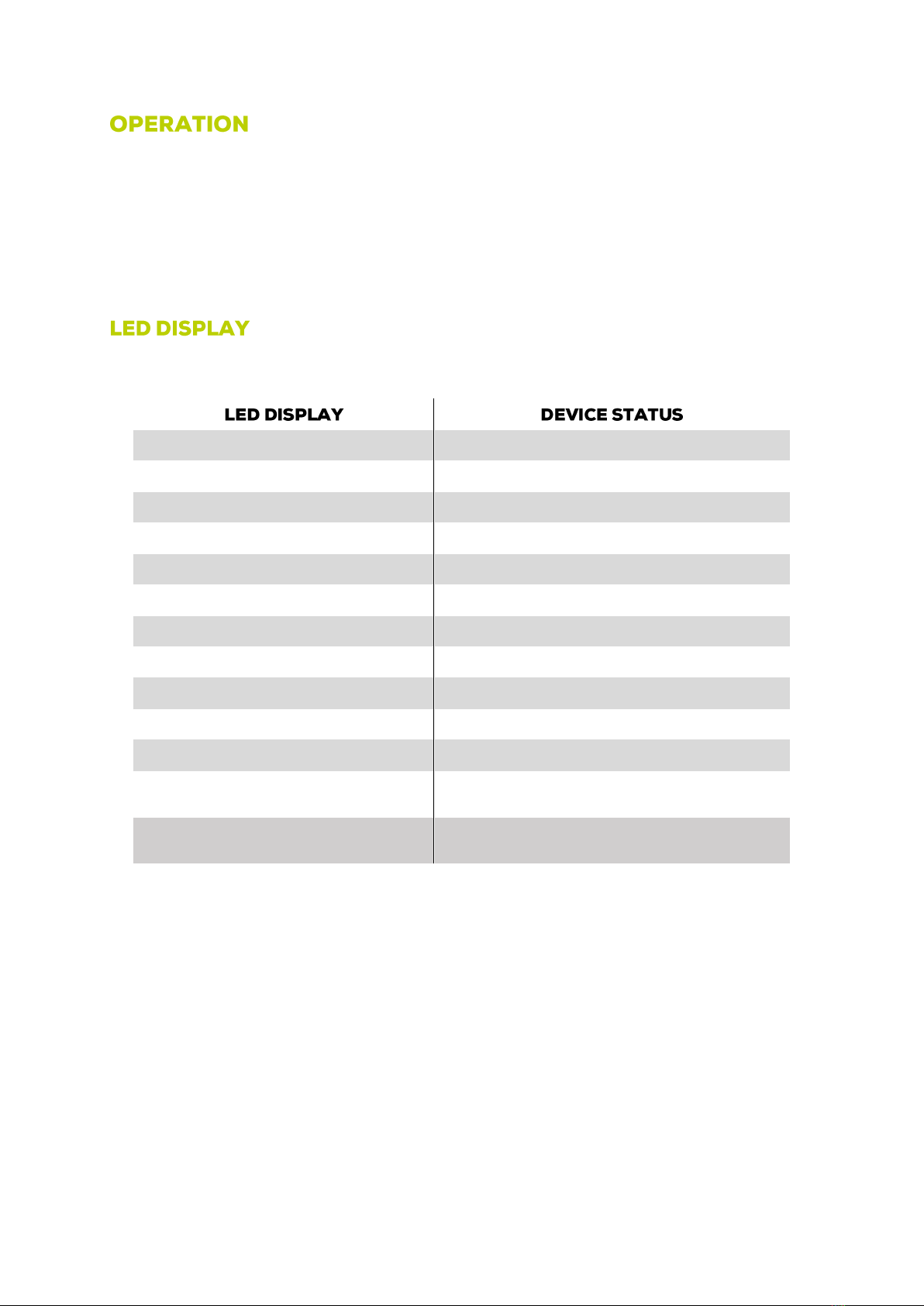
The wallbox is equipped with a separate LED indicator light for each charging cable, which shows the current status during
operation. From software V12 (see door inside)
green
No vehicle connected, wallbox ready for operation
blue
Box unlocked via RFID module
yellow
Vehicle connected, waiting state, charging process completed
green, slowly flashing
Vehicle is charging (more than 16A available)
red, flashing
Charging cable has short circuit, plug very dirty
red, 2x flashing
CP signal not stable, connector dirty
red, 3x flashing
Diode in vehicle defective, plug dirty
3 seconds flashing pink
RFID card not known / all RFID cards successfully deleted
3 seconds white
RFID card was taught
yellow flashing
Total power of the box limited via digital interface
light blue flashing
Power of a charging point limited via digital interface
red luminous
DC fault current >6mA, fault current sensor error or
connection error (from V12 restart of ALPHA required)
red and yellow flashing (from V12)
Ventilation requested by the vehicle therefore no charging
allowed
The LED indicator lights also show the preset current consumption every time the box is restarted.
10
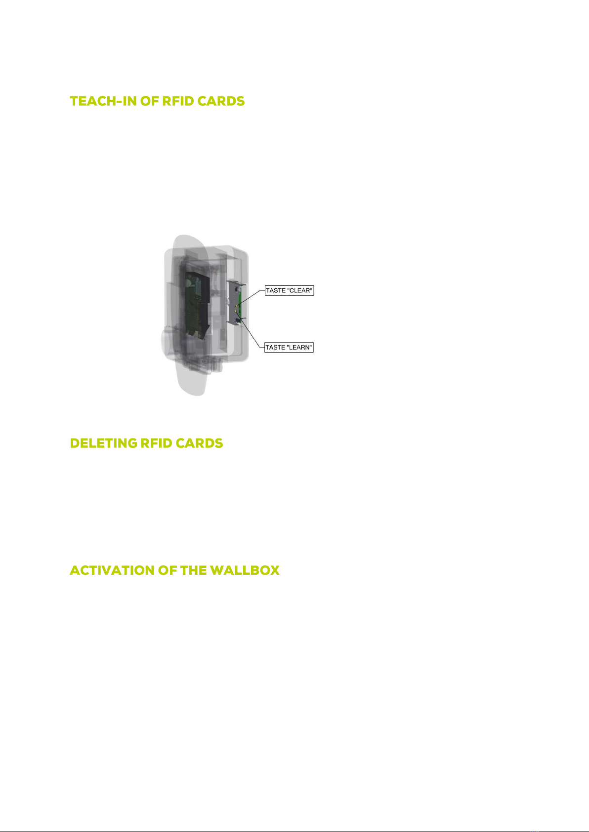
To use the RFID module, it is necessary to teach in at least one RFID card.
RFID cards are taught as follows:
1. Open the wallbox with the key provided for this purpose.
2. Press and hold the Learn button on the RFID module and place the card to be learned on the right outside of the
wallbox. (see Figure 4) A taught-in RFID card is signaled by a white status LED of the wallbox. In this way, up to 100
RFID cards, possibly also from third-party suppliers, can be taught.
Figure 4 Control panel of the RFID module
Note: It is not possible to delete individual RFID cards. The deletion process removes all previously taught-in cards.
1. First open the wallbox with the key provided for this purpose.
2. Start the deletion process by pressing and holding the Clear and Learn buttons on the RFID module until the LED
indicator flashes pink. The memory has been successfully deleted. This process can take up to one minute. (see
Figure 4)
3. Lock the wallbox.
There are two ways to start the charging process or to unlock the wallbox.
Option 1
1. Place a taught-in RFID card on the right-hand outside of the wallbox.
The wallbox signals the unlocking by a blue LED display.
2. Establish the connection between the wallbox and the vehicle to be charged within 30 seconds.
Option 2
1. First connect the wallbox to the vehicle to be charged.
2. Then unlock the wallbox by placing the RFID card on the right-hand side of the wallbox. In this case, too, the blue LED
indicator signals that the wallbox has been successfully unlocked.

11
In both cases, the charging process starts automatically.
Charging points to which no vehicle is connected are locked by the wallbox after 30 seconds.
As long as the connected vehicle is in the waiting or charging state, the connected charging point remains unlocked.
After completion of the charging process, the charging point in use is also locked.
Connect your vehicle to the wallbox.
As soon as the electric vehicle is ready for charging, the charging process starts automatically.
After successful charging, the vehicle ends the charging process automatically. Overcharging" is therefore not possible.
If two vehicles are charged at the same time, the wallbox regulates the available power. For example, the charging current is
divided between the two vehicles. If the charging process of one of the two vehicles is completed, the charging power of the
vehicle still charging is automatically increased.
Note: The time-delayed allocation of the charging current is not supported by all electric vehicles.
A charging current of at least 6A is required for each vehicle to be charged.
If the wallbox has been configured for a low charging current, this may mean that both vehicles cannot be charged at the same
time. In this case, the two connected vehicles are charged one after the other (sequentially).
If the charging process of the second vehicle does not start automatically, it may be necessary to disconnect the vehicle from the
system for a short time first. After reconnection, the charging process starts.
As a preventive measure, observe the connection sequence to the box. First connect the vehicle that does not support sequential
charging. Only then connect the second vehicle (sequential charging is supported by this one).
To restart the box, first disconnect all vehicles from the system.
Switch off the internal FI of the wallbox for 5 seconds.
After switching on the voltage, the microcontroller of the box restarts automatically.
Within 2 seconds, the box reports the preselected setting by white flashing of the LEDs, for example, 10 flashes signal a preset of
10 amps.
12
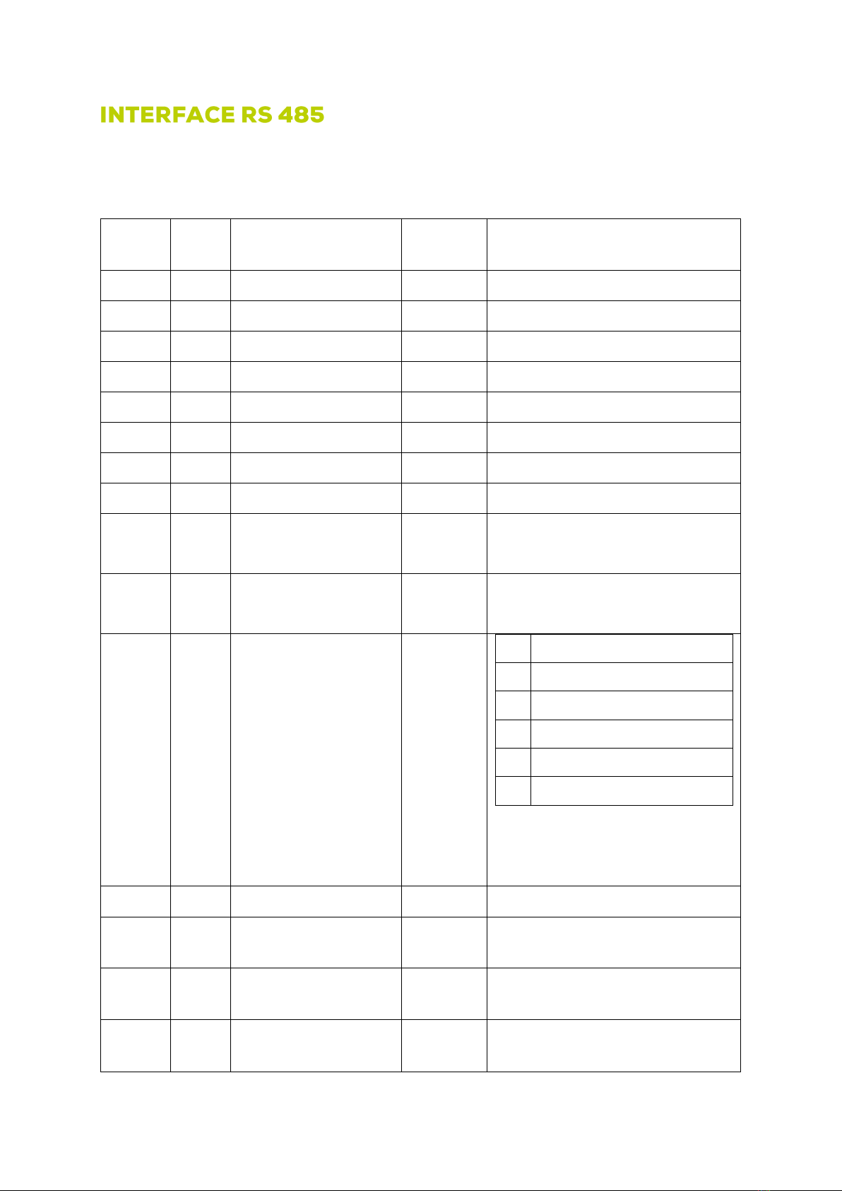
The RS 485 interface communicates with Modbus RTU, 9600 baud, 8 DATA bits, 1 stop bit, parity none, slave ID 1, unsigned
integer 16bit (UINT16, internal values 8 bit). The timeout is less than 2000ms.
Register type 40XXX read and write, register type 30XXX read only.
Modbus
address
Modbus
register
Initial value
Values type
0
40001
Modbus ID
1
1
40002
Modbus baud rate
96
(corresponds to 9600)
2
40003
max. current total limit
255
in A (values below 6 A lead to shutdown)
3
40004
max. current KFZ1 limit
255
in A (values below 6 A lead to shutdown)
4
40005
max. current KFZ2 limit
255
in A (values below 6 A lead to shutdown)
11
30012
Allocated current KFZ1
0
in A
12
30013
Allocated current KFZ2
0
in A
74
30075
taught RFID cards (number)
255
100
30101
Software version RFID and
Modbus module
255
Decimal value Software version
(D3 -> "3")
101
30102
Software version motherboard
255
Decimal value Software version
(V3 -> "3")
102
40103
Release register charge points
1
Share all
2
Lock all
11
Enable charging point 1
21
Lock charging point 1
12
Enable charging point 2
22
Lock charging point 2
Automatic locking takes place ~30 seconds after
release!
(Register available from software D2)
103
30104
Temperature in the box
255
(value register -72)*0.4244= Temp in °C
106
30107
Status KFZ1
255
0 no car, 1 car connected, 2 charging request, 3
charging request with fan, 4 short circuit
107
30108
Status KFZ2
255
0 no car, 1 car connected, 2 charging request, 3
charging request with fan, 4 short circuit
114
30115
Set charging current Supply
line
255
Value in A of the jumper position

13
115
30116
Set charging current Supply
line after corrections
Temperature and setting
255
Value in A that is available for all connected
vehicles in total.
116
30117
Lock status display
0
0
(0b00)
Box released
1
(0b01)
Charging point 1 locked
2
(0b10)
Charging point 2 locked
3
(0b11)
Both charging points locked
Information about RFID cards can be requested depending on the software version at support@pracht.com.
In the event of a defect, please contact the manufacturer directly.
Before cleaning, the wallbox must be disconnected from the power supply for safety reasons.
Dirt can be removed with a damp cloth.
The use of harsh cleaning agents is not permitted.
The wallbox must not be cleaned with a water jet or high-pressure cleaner.
Disposal of the packaging material is carried out via the collection containers for paper and plastics provided for your region.
The disposal of old devices and their accessories is carried out in accordance with the national and regional regulations for the
disposal of electrical and electronic devices. Accordingly, these must not be disposed of with household or bulky waste.
14
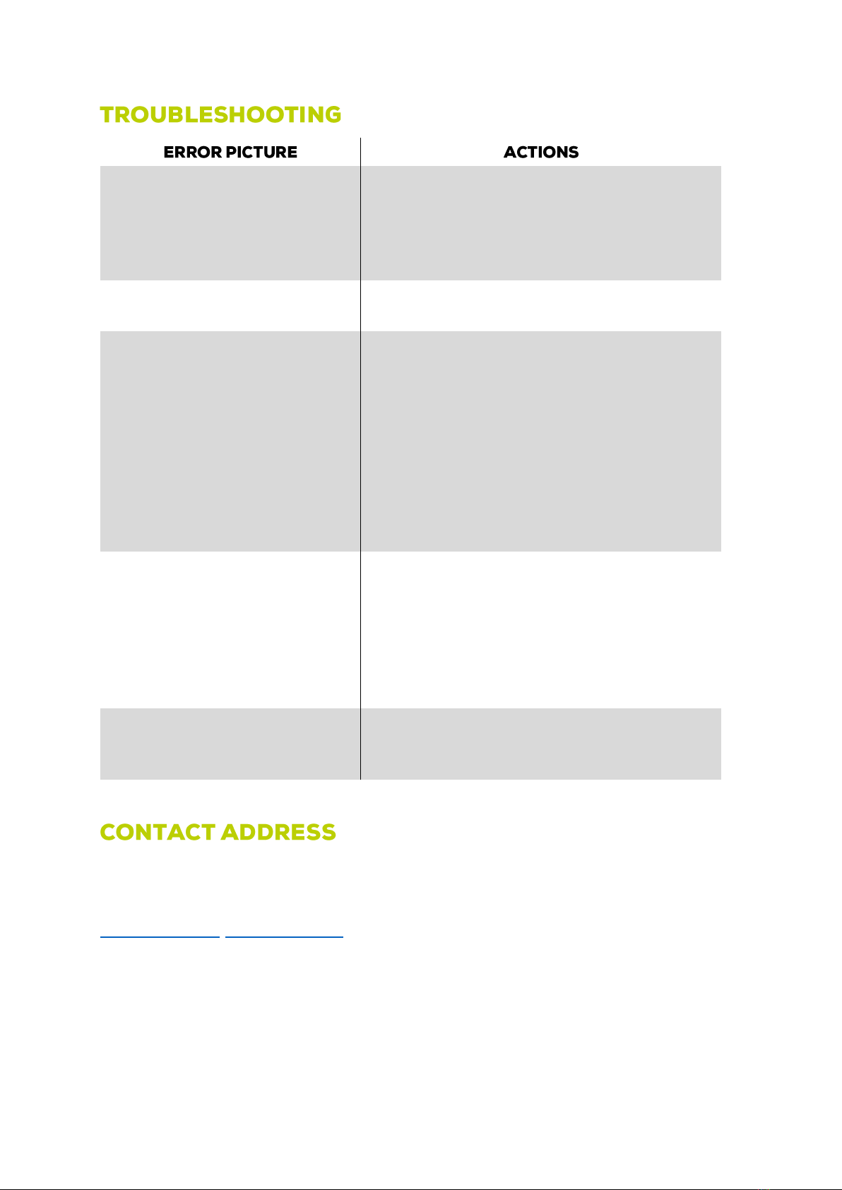
No function of the wallbox (LEDs extinguished).
•Check the fuses in the house distribution.
•Check the residual current circuit breaker (FI) in the house
distribution.
•Check the internal fuses.
•Check the internal residual current circuit breaker (FI).
Wallbox no longer responds.
•First disconnect all vehicles from the system. Then restart
the wallbox.
The wallbox signals a fault (red LED display).
•Disconnect the connection to the vehicle.
•Check the charging coupling and charging cable for possible
damage.
•In case of damage, disconnect the box from the power
supply and repair it.
•Check the contacts of the charging coupler for dirt. To do
this, disconnect the box from the power supply.
•After repair or cleaning, the wallboxcanbeconnected to the
mains. Once the fault has been rectified, the box is ready
for operation.
The vehicle suddenly charges with lower charging
current or briefly interrupts the charging process.
•The wallbox is equipped with thermal overload protection.
•From around 40°C outside temperature, the system
gradually reduces the maximum charging current.
•If the ambient temperature continues to rise, the wallbox
may switch off the charging process.
•As the outside temperature decreases, the wallbox
automatically continues the charging process.
The loading process was canceled.
•Restart the charging process. To do this, disconnect the
connection between the wallbox and the vehicle for 10
seconds.
PRACHT Industry GmbH
Am Seerain 3, 35232 Dautphetal-Buchenau, Germany
Tel. +49 6466 9140-900
info@prachtenergy.com, www.prachtenergy.com
Other manuals for ALPHA
2
This manual suits for next models
1
Table of contents
Other PRACHT Automobile Accessories manuals

Popular Automobile Accessories manuals by other brands


ULTIMATE SPEED
ULTIMATE SPEED 279746 Assembly and Safety Advice

SSV Works
SSV Works DF-F65 manual

ULTIMATE SPEED
ULTIMATE SPEED CARBON Assembly and Safety Advice

Witter
Witter F174 Fitting instructions

WeatherTech
WeatherTech No-Drill installation instructions

TAUBENREUTHER
TAUBENREUTHER 1-336050 Installation instruction