PRADA NARGESA CC90 User manual
INSTRUCTIONS BOOK
PRADA NARGESA, S.L
Ctra. de Garrigàs a Sant Miquel s/n · 17476 Palau de Santa Eulàlia (Girona) Spain
Tel. +34 972568085 · [email protected] · www.nargesa.com
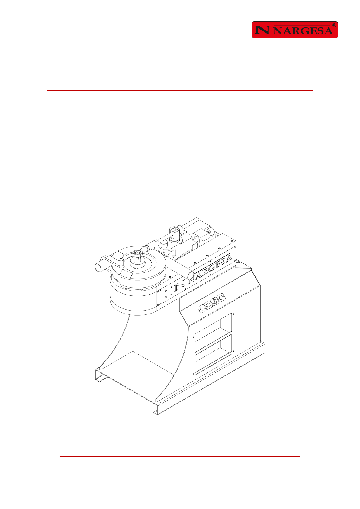
NON-MANDREL TUBE AND PIPE BENDER
CC90

Thank you for choosing our machines
www.nargesa.com

CONTENTS
1. MACHINE DETAILS ………....................................................................................................... 3
1.1. Machine Identification………......................................................................................... 3
1.2. Dimensions ................................................................................................................... 3
1.3. Description of the Machine ........................................................................................... 3
1.4. Machine Parts ............................................................................................................. 4
1.5. General Characteristics ….......................................................................................... 5
1.6. Description of the Guards ............................................................................................. 6
2. TRANSPORT AND STORAGE ……....................................................................................... 7
2.1. Transport …................................................................................................................... 7
2.2. Storage Conditions ………..…………............................................................................ 7
3. MAINTENANCE ……................................................................................................................. 8
3.1. Greasing Moving Parts …........................................................................................... 8
4. INSTALLATION AND START UP ……….................................................................................. 9
4.1. Machine Location ….................................................................................................... 9
4.2. Dimensions and Work Area ......................................................................................... 9
4.3. Acceptable External Conditions .................................................................................... 9
4.4. Instructions for Electrical Connection .......................................................................... 10
5. INSTRUCTIONS FOR USE ..................................................................................................... 11
5.1. Assembling the Roller and Counter-Die ............................................................. 11
5.2. Assembling the Radius Arm …………………..……..…………….……………………... 13
5.3. Changing Rotation Direction ………………………………………………………………. 14
5.4. Control Panel .............................................................................................................. 16
5.5. Manual Mode .............................................................................................................. 17
5.6. Angle Correction ……….……………………………………………………..……………. 20
5.7. Radius Arm ………………………………………………………………………………….. 20
5.8. Part Counter ………………………………………………….…………………………...… 21
5.9. Rotation Direction …………………………..………………………………………………. 22
5.10. Adjustment Tables ……………………………………………………………………… 24
5.11. Automatic Mode …………………………………………………………………………... 26
5.12. Remote Service …………………………………………………………………………. 29
5.13. Import/Export Parameters, Materials and Programs ………………………………..… 30
5.14. Touchscreen Calibration ……………………………………………………………...….. 32
6. ACCESSORIES ....................................................................................................................... 33
6.1. Optional Accessories .................................................................................................. 36
7. TROUBLESHOOTING.............................................................................................................. 42
TECHNICAL ANNEXES
- 3 -
1. MACHINE DETAILS
1.1. Machine Identification
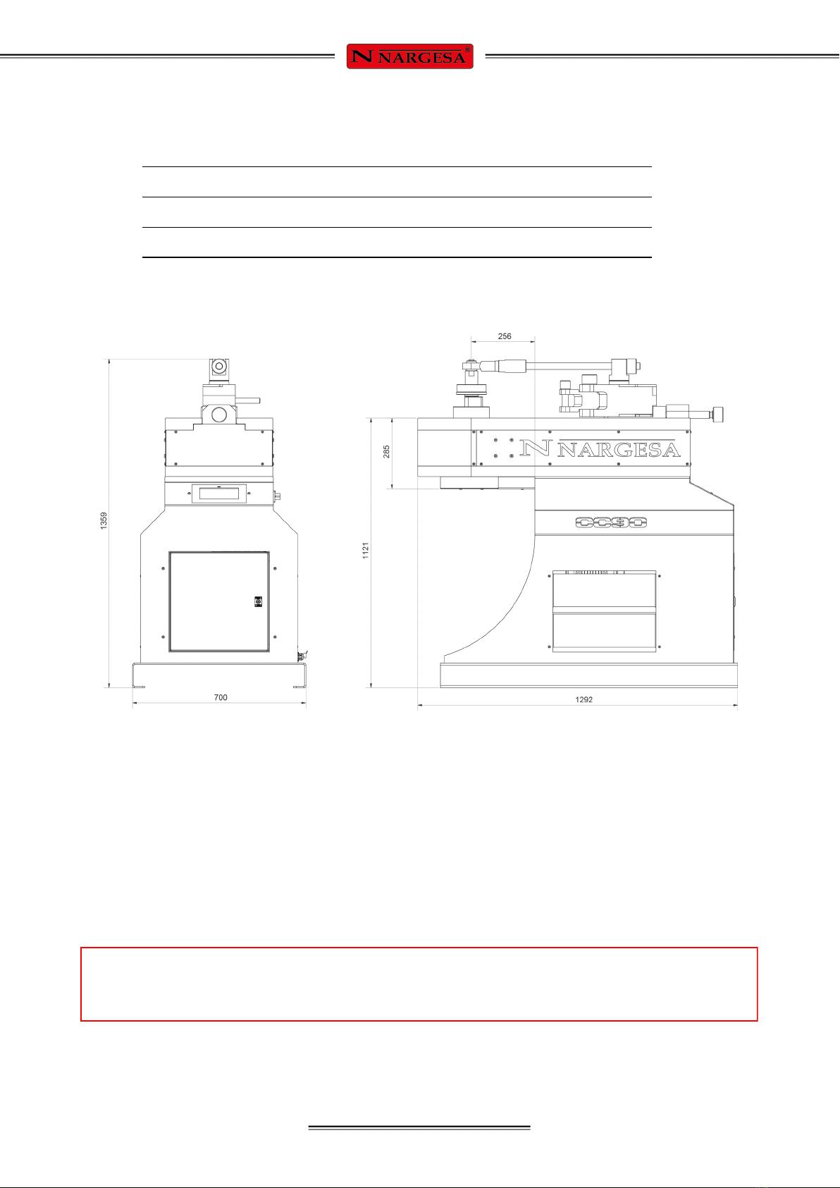
1.2. Dimensions
Figure 1. Outside Dimensions of Bender CC90
1.3. Description of the Machine
The non-mandrel pipe bender CC90 is a machine specifically designed to bend profiles, mainly metal ones,
of different thicknesses and configurations: pipes, solid profiles, T-profiles, angles...
The bender comes standard with a radius arm that must be used to bend thicker pipes of larger diameters.
Besides standard rollers, PRADA NARGESA manufactures different types of additional rollers for all types
of bending based on the configuration of the material to be worked.
PRADA NARGESA S.L. is not liable for any damages that may be caused due to improper use or
a breach of the safety rules by users.
Make NARGESA
Type Non-Mandrel Pipe Bender
Model CC90

- 4 -
NON-MANDREL TUBE AND PIPE BENDER CC90
1.4. Machine Parts
Roller Radius arm
Spindle
Drag Clamp
Counter-die
Positioner
CNC Control
Shelving

- 5 -
Figure 2. Characteristics plate
1.5. General Characteristics
Reference 100-17-02-001
Engine power 2,2 Kw / 3 HP
Tension 230/400V 50/60Hz Three-Phase
230V 50/60Hz Single-Phase
Automatic rotation speed 0,7 to 1,8 r.p.m.
Intensity 9/5 A
Minimum radius of curvature 3 times the pipe diameter
Maximum radius of curvature 375 mm
Max. cap. round steel pipe 88,9mm or 3" Schedule or 3" 1/2 x 6mm.
Max. angle of curvature 180º
Dimensions 700x1292x1359 mm
Weight 965 Kg

- 6 -
NON-MANDREL TUBE AND PIPE BENDER CC90
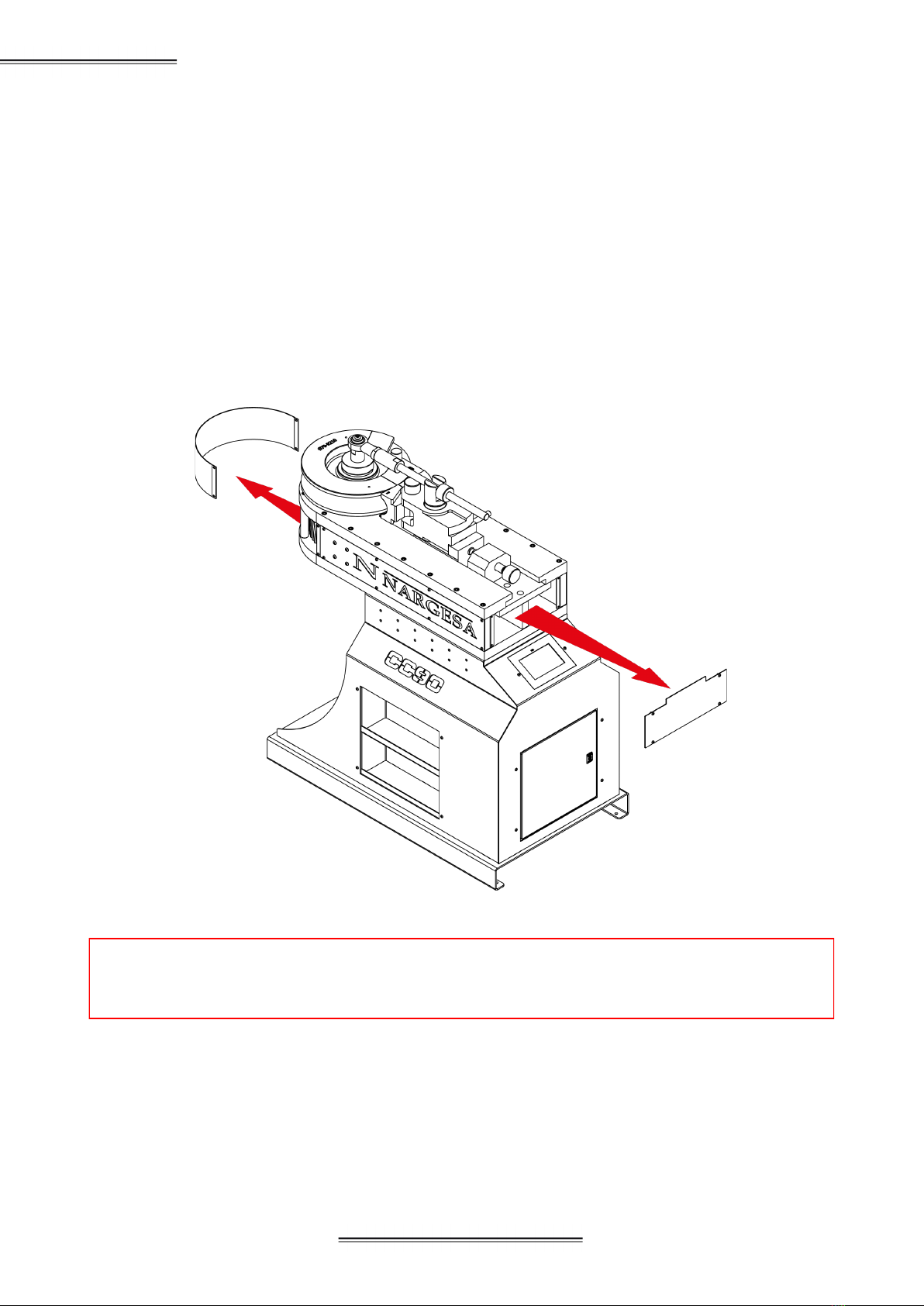
1.6. Description of the Guards
The gear box and all the gears enabling the machine to operate are inside the main structure which pro-
tects the mechanisms.
Despite the fact the main moving parts are protected by the front cover, special precaution must be taken
when bending to prevent entrapment between the die, counter-die and part.
Figure 3. Mechanism Protection Guards
Front guard
Rear guard

- 7 -
2. TRANSPORT AND STORAGE
2.1. Transport
The machine should be transported as follows:
- Along the bottom at the base of the machine using a forklift or lift truck as indicated in the illustration.
Never raise the machine more than 200 mm off the ground or it may tip over.
Figure 4. Moving the machine
2.2. Storage Conditions
The pipe bender may not be stored anywhere that does not meet the following requirements:
- Humidity of 30% to 95%
- A temperature of -25ºC to 55ºC or 75ºC over periods not to exceed 24 hours (please remember these
temperature are for storage conditions)
- Do not pile machines or place any heavy objects on top
- Do not dismantle for storage
- 8 -
NON-MANDREL TUBE AND PIPE BENDER CC90
ATTENTION: To grease the machine, you must stop the machine and press the “Emergency Stop”
button.
3. MAINTENANCE
3.1. Greasing the Moving Parts
Keeping the moving parts on the machine clean whenever possible is recommended to ensure proper
operation and extend the service life.
To grease the pinions on the CC90, do as follows:
- Remove the front guard and rear guard to access the pinions.
- Apply grease to the teeth of the pinions using a brush or spatula.
- Distribute the grease evenly without creating any excess or accumulation.
- Grease the machine periodically depending on the use. Recommended by the manufacturer: once a year.
- 9 -
4. INSTALLATION AND START UP
4.1. Machine Location
Try to position the machine in the proper location so that it does not have to be moved; otherwise, following
the steps described in the transport section (no. 2). Position over a smooth, level surface to prevent vibra-
tions and movements during bending operations.
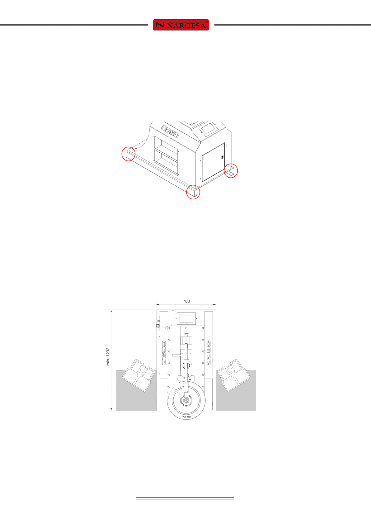
The machine can be secured with bolts as it comes with a base or pedestal on the bottom with four holes
as shown in the following figure.
Figure 5. Anchoring points on the machine
4.2. Dimensions and Work Area
Take the dimensions, operator work area and the lengths of any materials to be worked into consideration
when positioning the machine.
The pipe bender may be used by a single operator who must stand on one of the two sides of the machine
to control the materials during processing.
Before starting the bending process, the operator shall adjust the roller and counter-die to the material
while the machine is off.
Figure 6. Operator’s work area
4.3. Acceptable External Conditions
- A room temperature of between +5 ºC and +40 ºC without exceeding an average temperature of +35 ºC
over 24 hours.
- Moisture between 30% and 90% without water condensation.

- 10 -
NON-MANDREL TUBE AND PIPE BENDER CC90
The pipe bender CC90 is equipped with a 230 V 1.1 kw engine for operation with the Roller. The machine
must be connected to 220 V compatible supply voltage compliant with the requirements specified.
IMPORTANT
This machine must be connected to an earthed socket.
Before making any change in the wiring or the electric panel,
you need to make sure the machine is not connected to the power supply system.
4.4. Instructions for Electrical Connection
- 11 -
5. INSTRUCTIONS FOR USE
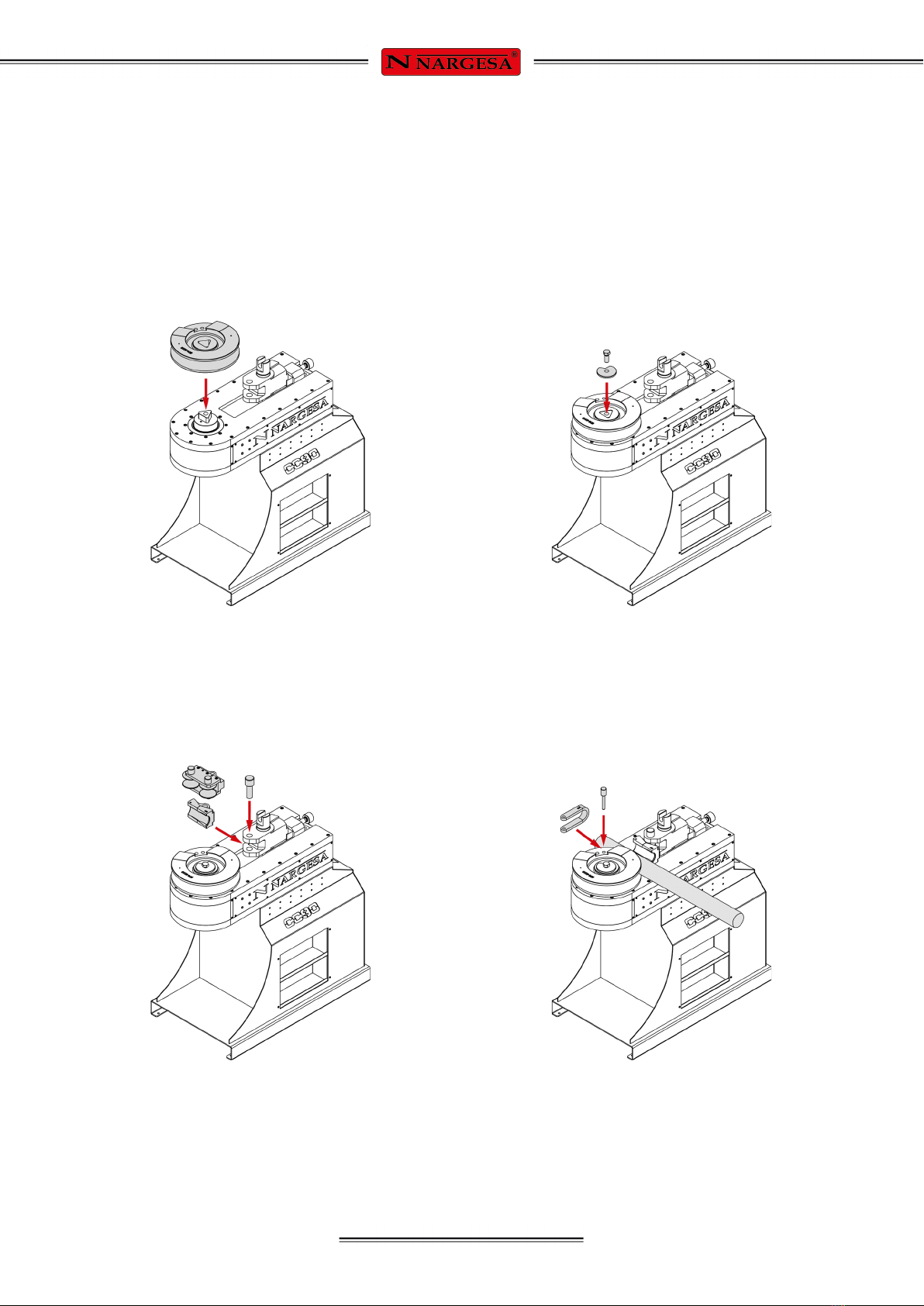
5.1. Assembling the Roller and Counter-Die
The roller shall be assembled as follows:
1. Place the roller in the machine axis. The built-
in centring pin will prevent an incorrect position.
2. Secure the roller with the washer and screw.
3. Put the counter-die or support rollers in the
positioner and secure.
4. Put the material in the roller guide and
secure to the drag clamp.

- 12 -
NON-MANDREL TUBE AND PIPE BENDER CC90
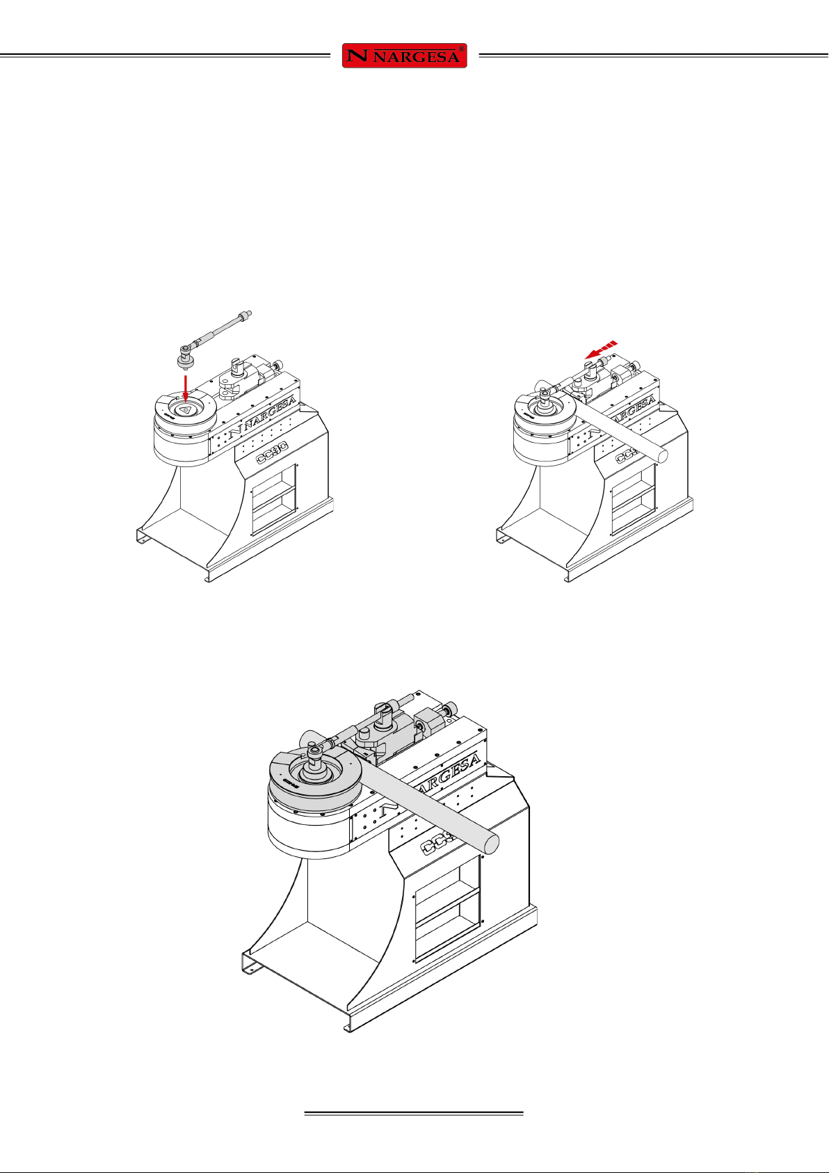
5. Lubricate the pipe and the counter-die with
BEND8 spray.
7. Secure the positioning spindle with your
hands to the machine table.
6. Slide the counter-die positioner until adjusted
to the material.
- 13 -
2A. Secure the roller with the radius arm. 8. Place the radius arm in the positioner
channel and adjust the nut with your hands
until secure and fixed.
5.2. Assembling the Radius Arm
If the radius arm must be used, switch step 2 with 2A as explained below.
And follow step 7 with number 8 as explained below.

- 14 -
NON-MANDREL TUBE AND PIPE BENDER CC90
1. Remove the positioning spindle. 2. Remove the positioner and counter-die.
5.3. Changing the Rotation Direction
The non-mandrel pipe bender CC90 is programmed to rotate counter-clockwise. When the rotation direc-
tion must be changed, make the following position changes:
IMPORTANT
Remove the material from the machine to make this change.
3. Remove the drag clamp. 4. Remove the counter-die.

- 15 -
5. Position the roller with the CNC. See section
5.8. Rotation Direction.
6. Turn the positioner 180º degrees and insert it
back in the carriage.
8. Put the drag clamp back on.7. Rotate the counter-die 180º and secure with
the pin.

- 16 -
NON-MANDREL TUBE AND PIPE BENDER CC90
5.4. Control Panel
On
Automatic
Manual
Menu
Manual rotation to the right
Rotation direction to the left
Rotation direction to the right
Automatic unlocking
Manual rotation to the left
Diameter of the material
Roller Radius
Operating speed
Thickness of the material
Corrector
Part counter
Repetitions
- 17 -
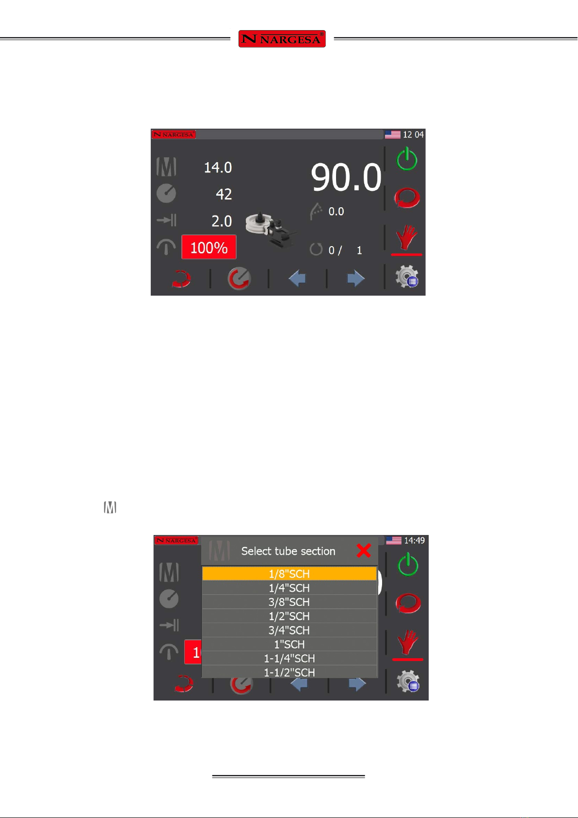
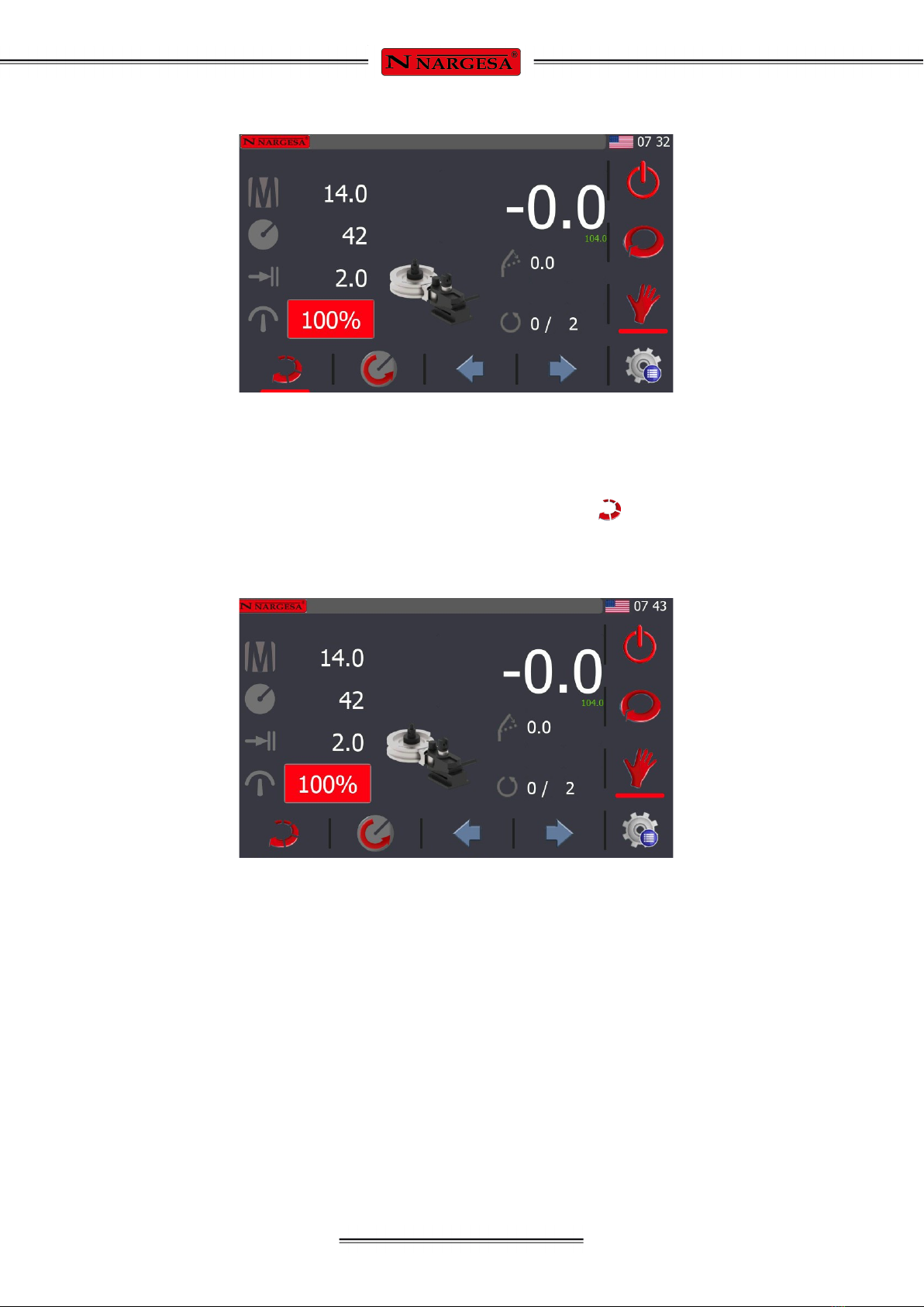
5.5. Manual Mode
To turn on the machine, place the Start Switch in the Connected position. The initial interface appears on
the screen:
The machine is now in Standby; in other words, the machine is active yet at rest waiting for any operation
order.
The CC90 is already started and in Standby. To activate it, follow the steps indicated below.
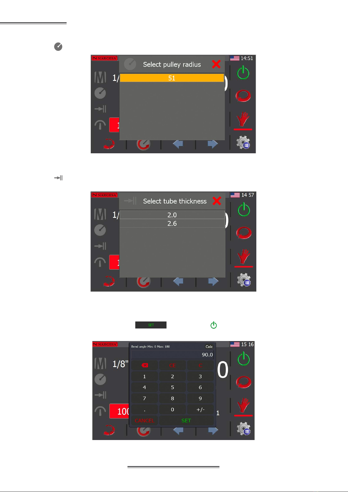
Enter the following operating details:
- Diameter of the material
- Roller radius
- Thickness of the material
- Bending angle
Press each of the items on the screen to enter all these parameters.
Press the key to choose the diameter of the material to be curved:
- 18 -
NON-MANDREL TUBE AND PIPE BENDER CC90
Press to choose the roller radius.
Press to choose the thickness of the material:
To determine the bending angle, press the number that appears at the top right of the screen and enter the
value; in this case, 90 degrees. Press to accept and to start the machine.
- 19 -
The machine will work at minimum speed based on the parameters entered.
If necessary, enable the automatic unlocking option by pressing the icon . This means the machine
will automatically unlock by rotating in the opposite direction of the bending a few degrees to unlock the
material. If it is not necessary, disable this icon.
Table of contents
Other PRADA NARGESA Construction Equipment manuals


