SPARE BENDING FORMERS
OF DOUBLE FRAME OPEN BENDING
(For short radius heavy & thin wall thickness bending upto 180°)
PROD. I.D. O.D. RADIUS MIN.WALL N.W.T
NO. INCHES MM MM THICKNESS MM (Kgs)
225A 3/8 16.7 80 2.65 5.100
225B 1/2 21.0 80 2.65 5.000
225C 3/4 26.4 80 2.65 4.500
225D 1 33.2 110 3.25 9.500
225E 1.1/4 42.0 160 3.25 11.550
225F 1.1/2 47.8 160 3.25 12.000
225G 2 60.3 200 3.65 19.600
FEATURES
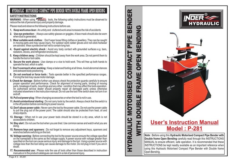
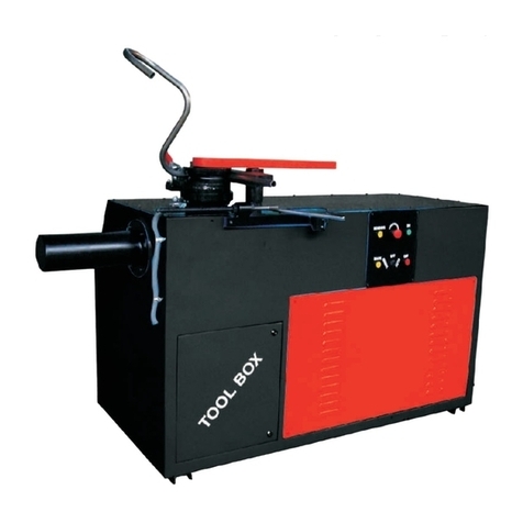
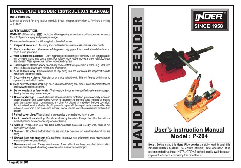
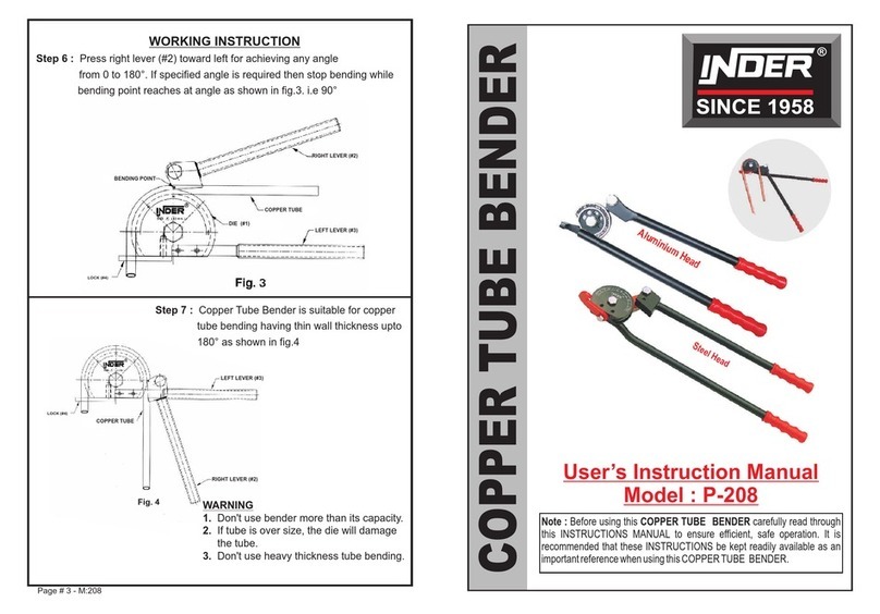
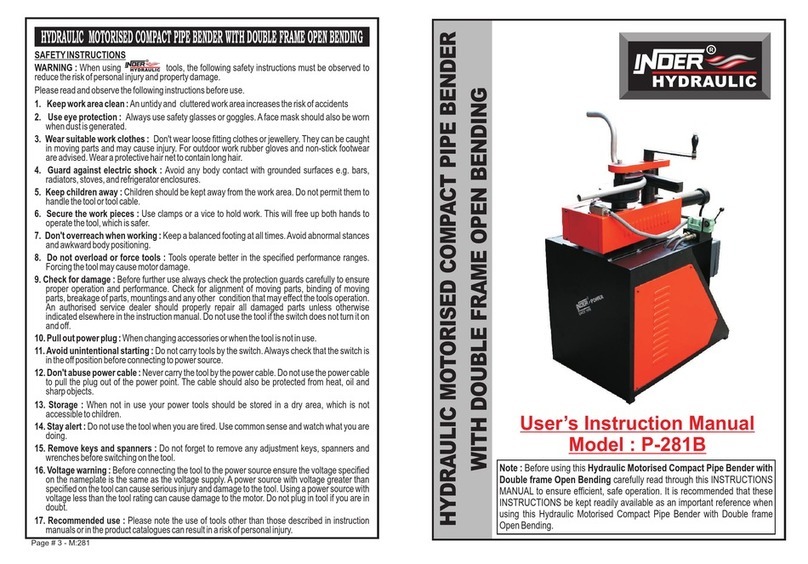
"INDER" HYDRAULIC MOTORISED PIPE BENDERS WITH DOUBLE FRAME OPEN
BENDING is specially self designed for short radius heavy & thin wall thickness bending
3/8" - 2" Gas, Water, Steam & stainless steel pipe upto 180° "U" bending. In this version
providing extra pump force 15 tons, well Grinding/Hardcrome Ram/Piston with automatic
return will spring to release of valve.
PROD. NO. 225
Page # 1 - M:222
Prod. No. Pipe Size Formers Size Formers Size Formers Size
(O.D.) in (O.D.) in Inches (O.D.) in Inches (O.D.) in Inches
Inches FOR GAUGE 18 FOR GAUGE 16 FOR GAUGE 14
209A 1/2 8 7 6
209B 3/4 9 8 7
209C 1 9 8 7
209D 1.1/4 12 12 10
CONDUIT PIPE SIZE
Please state when placing the order for conduit Pipe Bender for furniture pipe
PROD. NO. 222
R
Bending radius R
is always calculated
from the middle of
the pipe.
HYDRAULIC MOTORISED PIPE BENDER
WITH DOUBLE FRAME OPEN BENDING
(For short radius heavy & thin wall thickness bending upto 180°)
PROD. SIZE IN PUMP HYDRAULIC MOTOR N.WT. G.WT
NO. INCHES FORCE OIL POWER/KW (Kgs) (Kgs)
IN TONS IN LTR. lll PHASE 440V
222A 3/8 TO 1.1/4 15 1.750 1.5 204.0 269.0
222 B 1/2 TO 2 15 1.750 1.5 244.0 309.0
DEFECT AND REMEDY
DEFECT : Dust particles in filter portion.
REMEDY: Open complete drain plug (#25) as shown in the figure 8 and clean filter (#24)
throughly as shown in the figure 9
DEFECT : If Ram/Piston does not move from the place while pumping and it go and back on
same place.
REMEDY: Loose release valve (#20) in anti clockwise & switch on the machine for 20
seconds & again tight release valve (#20) in clockwise direction & repeat this
operation 4-5 times as shown in figure 10
It results are not satisfied, remove four L - Key bolt (#47) & remove motor & open
screw (#29) & clean its three parts i.e. Ball (Big) (#28), Weight Pin (#27), Ball
(Small) (#26) & again fit all four parts as shown in figure 11
HOW TO REPLACE/FIT PUMP PLUNGER
Step 1 : Open four pieces L- key bolts (#47) & remove motor (#65).
Step 2 : Get the complete plunger (#41 to #45) out & clean.
Step 3 : Replace the damage seals, if found.
Step 4 : Fit all parts of pump plunger again turn by turn as shown in figure 13.
Ball (#41) - Surfacer (#42) - Nylon washer (#43) - Double spring (#44) - Fit bucket
(#45A) on plunger shaft (#45)- Fit oil seal (#45D) in side the plunger (#45B) & O-
ring (#45C) on out side the plunger. Insert plunger shaft (#45) into plunger (#45B)
from the bottom side as shown in figure 13. Otherwise bucket will damage, put the
motor (#65) on the cylinder & hold it with 4 L-Key bolt as shown in figure 12.
Page # 6 - M:215
Figure 8 Figure 9
24
25
25
24
Figure 13
41
45D
45C
45B
45 45A
44
43
42
Back
20
OFF
ON
Figure 10
Figure 11
Figure 12
29
28
Drops
27
26
L - Key
42
47
