Prairie Labs Precision JDM-150 Product manual

!
TECHNICAL REFERENCE MANUAL
AND INSTALLATION GUIDE

!
PRAIRIE PRECISION NETWORK TECHNICAL MANUAL 2016
2
TECHNICAL REFERENCE MANUAL
CONTENTS
Introduction......................................................................................................................3
Key Features................................................................................................................4
Unique Features............................................................................................................5
Disclaimer...................................................................................................................6
Specifications..............................................................................................................7
Installation.......................................................................................................................9
Antenna Location.......................................................................................................9
GPS Antenna..............................................................................................................9
System Requirements................................................................................................10
SIM Card Installation and Data Usage......................................................................10
SF3000 Connection...................................................................................................11
Modem Mounting......................................................................................................12
Display Setup..................................................................................................................13
RTK System Status....................................................................................................14
RTK Diagnostics........................................................................................................15
Appendix A – Status Indicators......................................................................................16
Appendix B – Cellular Antennas and Amplifiers...........................................................18
Appendix C – Glossary...................................................................................................20
!

!
PRAIRIE PRECISION NETWORK TECHNICAL MANUAL 2016
3
TECHNICAL REFERENCE MANUAL
INTRODUCTION
Congratulations on the purchase of your Prairie Precision JDM-150 Modem. The JDM-150 RTK
Modem represents the third generation of RTK Network communications devices allowing the
John Deere SF3000 receiver to easily and reliably connect to any internet GPS/GNSS Corrections
source all the while being managed remotely without any interaction required on the end-users
part.
The goal of this manual is to provide technical information as well as an installation guide to aid
you with the start up of your PPN Network RTK system.
If you have any further questions to this guide please contact your local PPN reseller for further
information.
!

!
PRAIRIE PRECISION NETWORK TECHNICAL MANUAL 2016
4
TECHNICAL REFERENCE MANUAL
KEY FEATURES
•Connects to NTRIP Casters to retrieve RTK corrections
•Connects to direct TCP/IP port streams to retrieve RTK corrections
•Supports NTRIP authentications
!

!
PRAIRIE PRECISION NETWORK TECHNICAL MANUAL 2016
5
TECHNICAL REFERENCE MANUAL
UNIQUE FEATURES
•Integrated 2G/3G Cellular Modem able to roam on any HSPA, GSM or CDMA
capable network
•Communications pecking order, which intelligently and automatically scans looking
for RTK Corrections from Cellular networks, Wi-Fi, and 900 MHz
•Remotely monitor and reconfigure while device is in operation through our online
admin tool as well supports'local'configuration via RS-232 serial port commands.
•Standard RS232 port for easy cable setup and prototyping
•Cached GPS positions allows the JDM-150 to function without position from internal
GPS receiver improving its robustness over older generation RTK Bridges
•High performance integrated aGPS receiver (no external cables required) that will
typically achieve a positional fix in under 10 seconds
•Integrated 900 MHz radio (optional) for signal repeating to slave JDM-150 Modem
systems
•Creates an automatic Wi-Fi hotspot when connected to your cellular carrier for use by
other Wi-Fi enabled devices.
!

!
PRAIRIE PRECISION NETWORK TECHNICAL MANUAL 2016
6
TECHNICAL REFERENCE MANUAL
DISCLAIMER
While every effort has been made to ensure the completeness and accuracy of the PPN RTK
Modem Users Guide (this document), PPN assumes no responsibility for omission and errors.
Nor is any liability assumed for losses or damages resulting for the user of the information
contained herein. As with all wireless communication devices and GPS systems, numerous
factors affect the availability and accuracy of these systems (e.g. obstructions, interference,
system maintenance, availability, etc.).
Therefore, Prairie Precision Network, your cellular provider, your GPS/GNSS corrections
provider and even the manufacturer of your GPS system cannot guarantee the accuracy,
continuity, or availability of the complete system due to the numerous variables. Being well
educated on these many factors will improve your ability to plan, troubleshoot, and overcome
these limitations insuring maximum productivity with our equipment. Contact your local PPN
reseller regarding education classes on your compete equipment.
!

!
PRAIRIE PRECISION NETWORK TECHNICAL MANUAL 2016
7
TECHNICAL REFERENCE MANUAL
Size!
35 mm x 79 mm x 140 mm (1” x 3” x 5.5”)!
Weight
!
450 g (1.0 lbs.)!
Voltage Range
!
9 – 25 VDC!
Max Power Consumption
!
1 amps at 12VDC when Wi-Fi & 900 MHz
active!
Operating Temperature
!
-30°C to +70°C (-40°F to +158°F)!
Storage Temp Range
!
-40°C to +85°C (-40°F to +185°F)!
Humidity
!
100%!
Condensing Ruggedness Rating
!
IP67
MIL-STD-810G 527!
Cellular Functionality Compatibility:
•
EV-DO/EV-DO Rev. A 800MHz*
•
EV-DO/EV-DO Rev. A 1900 MHz*
•
HSDPA/HSUPA 800MHz*
•
HSDPA/HSUPA 850MHz*
•
HSDPA/HSUPA 900MHz*
•
HSDPA/HSUPA 1900MHz*
•
HSDPA/HSUPA 2100MHz*
•
GSM/GPRS/EDGE 850MHz
•
GSM/GPRS/EDGE 900MHz
•
GSM/GPRS/EDGE 1800MHz
•
GSM/GPRS/EDGE 1900MHz
* Receive Diversity on all HSPA/UMTS/EV-
DO/CDMA bands Data Speeds:
•
HSDPA/HSUPA DL/UL – 7.2 Mbps/5.76
Mbps
•
WCDMA DL/UL – 384 kbps/384 kbps
•
GSM DL/UL – 14.4 kbps/14.4 kbps
•
GPRS DL/UL – 85.6 kbps/42.8 kbps
•
EDGE DL/UL – 236.8 kbps/118.4 kbps
•
EV-DO FL/RL – 3.1 Mbps/1.8 Mbps
•CDMA 1xRTT FL/RL – 153 kbps/153 kbps
Cellular Connector
TNC Female
Wi-Fi Capabilities
Client, WAP (Wireless Access Point)
802.11 b
802.11 g
WEP
WAP
WAP2
Wi-Fi Antenna
No Connector (Internal Antenna)
900 MHz SSR Transceiver
SMA Female
FHSSR – Frequency Hopping Spread
Spectrum
100 – 1000 mW Selectable
Master / Multiple Slave
SPECIFICATIONS

!
PRAIRIE PRECISION NETWORK TECHNICAL MANUAL 2016
8
TECHNICAL REFERENCE MANUAL
L1 GPS
!
No Connector (Internal Antenna)
Standalone Positioning and aGPS
Indoor GPS utilizing OneXTRA
Position caching for indoor operation with
complete GPS blockage
TTFF < 10 seconds
Serial
!
3 Wire RS232 MOLEX – Numerous
Connector Solutions!
Power Connector
!
2 Wire MOLEX – Numerous Connector
Solutions Available (see parts listing for
complete list):
•
SAE
•
Unterminated
•
Serial power using device power
!
Status Indicators
!
Status Lights (Power, Cellular/Wi-Fi, John
Deere Translator, Radio, Mode)!

!
PRAIRIE PRECISION NETWORK TECHNICAL MANUAL 2016
9
TECHNICAL REFERENCE MANUAL
INSTALLATION
Modem Antenna Location:
If you are operating in areas of questionable cellular coverage utilize the supplied
external antenna mount and/or amplifier. Mount the cellular antenna as high as possible
and as perpendicular to the surface as possible.
Most high gain antennas require a “Ground Plane” for optimal operation. Refer to your
antenna’s documentation on the size of the ground plane as it relates to the operational
frequency (bigger is always safer, i.e. a 24” ground lane will work with frequencies all
the way down to VHF.
Also, an important consideration in determined the location to mount the PPN Modem is
to avoid mounting in close proximity to any of the GPS guidance antennas / globes as
poorly filtered GPS Receivers can be affected by any cellular / Wi-Fi device.
Recommended distance from GNSS receiver is 3 feet or more for the JDM-150 modem.
!
!
Internal GPS Antenna
The main requirement of the internal GPS Antenna is that the JDM-150 modem be
mounted vertically so that the internal GPS antenna has a good view of the sky. If it
does not, it may delay the acquisition of the correct position delaying the login time to
your RTK Provider and therefore it will take longer to achieve a Fixed RTK Position. In
the situation where the internal GPS receiver cannot obtain a GGA position, the PPN
Modem will fall back to the last stored/cached position after 3 minutes.
!
!
PRAIRIE PRECISION NETWORK TECHNICAL MANUAL 2016
10
TECHNICAL REFERENCE MANUAL
INSTALLATION INSTRUCTIONS
Requirements
•John Deere GNSS Receiver
(SF3000 or higher)
•RTK activation on Receiver
•GS2 1800/2600, GS3 2630, GS4
4100/4600
Installation steps
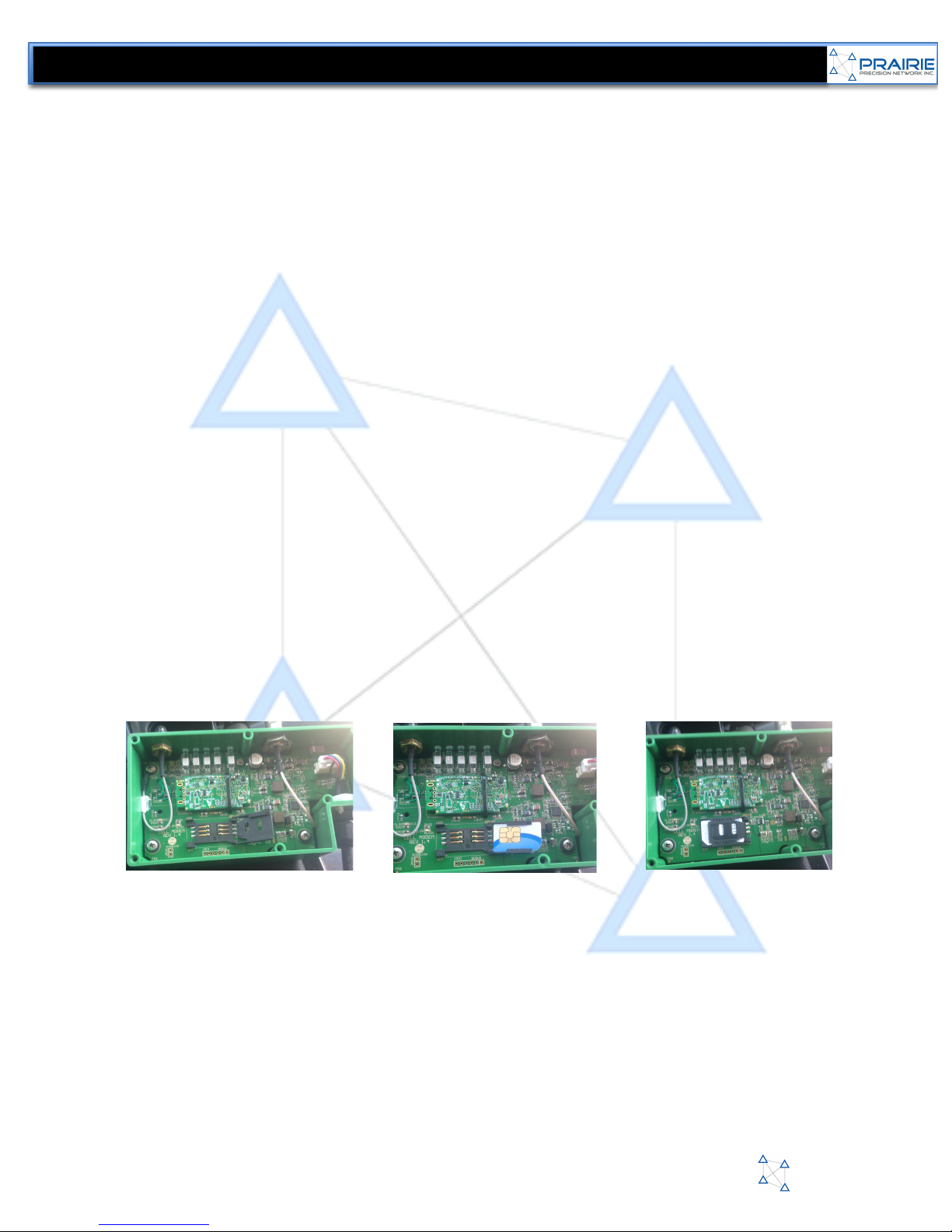
1) INSTALL SIM CARD INTO MODEM*
a. A standard size SIM card will need to be purchased and activated by a local
Telco to install into the modem. We work with all major carriers, Bell,
Telus, Rogers and Sasktel. If using MTS please contact your PPN reseller
as an internal settings update will need to be done.
b. Take all 6 screws out of cover of modem and set aside
c. Open Sim card slot by pushing back and lifting cover (figure 1)
d. Insert SIM card with printed circuit board facing you with the SIM card slot
open (figure 3)
Figure!1!
Figure!2!
Figure!3!
•PPN RTK Modem
•Standard SIM card with active data plan
•Brackets and high gain antenna
•AutoTrac Activation on Display
!
*SIM CARD DATA USAGE
The PPN Modem does have a wifi antenna in it that can create local hotspots.
You can choose to turn on or off this feature.
WIFI OFF – approx. 30-40 Mb of data will be used during an average working day for the
RTK Network corrections. Meaning a 1-2 Gb data plan for a month will cover this setup
WIFI ON – this amount of data usage is completing dependant on WIFI usage.
You should only be using an unlimited plan to make sure to cover all data usage.

!
PRAIRIE PRECISION NETWORK TECHNICAL MANUAL 2016
11
TECHNICAL REFERENCE MANUAL
Figure!4!
Figure!5!
Figure!6!
2. MODEM CONNECTION TO STARFIRE
a. Open the receiver by removing the three screws underneath so that you
can locate the 4 pin square connector (figure 4)
b. Connect the PPN Modem harness to this connector through the back
rubber grommet on receiver and close receiver. (figure 5 & 6)
!

!
PRAIRIE PRECISION NETWORK TECHNICAL MANUAL 2016
12
TECHNICAL REFERENCE MANUAL
Figure!7
3. MOUNTING THE PPN MODEM
a. You can choose to mount the PPN Modem either on the roof or inside the cab.
Inside Cab Mount
a. Order JDB-150CBK (figure 7) and JDB-150EXT (figure 8)
b. Install JDB-150EXT into globe as described in step# 2
c. Run JDB-150EXT back into cab and connect it to the JDM-150 Modem
d. Choose any “lower” cab bolt to mount the JDB-150CBK to and then fasten
modem to this bracket (do not mount on a bolt close to cab roof)
e. Make sure that the JDM-150 is mounted vertically and has a good view of the sky
(figure #9)
f. Connect high gain antenna to modem and run out to top of cab to get best possible
cellular reception. Place antenna plate under one roof bolt and then place antenna
on plate
!
Figure!9
Figure!8

!
PRAIRIE PRECISION NETWORK TECHNICAL MANUAL 2016
13
TECHNICAL REFERENCE MANUAL
Figure!10
Roof Mount
a. Order JDB-150RMK (figure 10)
b. Remove Plastic cover and mount modem to bracket (figure 11)
c. Replace plastic cover by making sure to connect both wire leads in it to the
corresponding connector on the modem (figure 11 & 12)
d. Mount JDB-RMK under one of the roof bolts on top of cab (figure 13)
e. Connect High gain Antenna to TNC connector on JDB-150RMK (Figure 13)
f. Mount antenna plate to other roof bolt and place antenna on it!
Figure!11
Figure!12
Figure!13
!
PRAIRIE PRECISION NETWORK TECHNICAL MANUAL 2016
14
TECHNICAL REFERENCE MANUAL
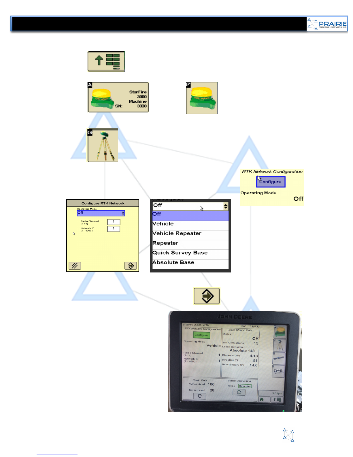
Display Example (Will vary based on the display and firmware version)
a. Press
b. Press then Press
c. The SF3000 Main Info screen will display.
d. Press to display the base station status and radio configuration screen.
e. Press Configure to access the RTK Network Configuration page
f. Select the box under “Operating Mode” that will say “OFF”
g. From the List choose “Vehicle” and you will be returned to the configure RTK Network
Page
h. Leave the Radio and Channel ID at “1” then hit
i. Your RTK Setup Page should look
like the image to the right. Most of
the information on this page is not
needed for a VRS network solution.
!

!
PRAIRIE PRECISION NETWORK TECHNICAL MANUAL 2016
15
TECHNICAL REFERENCE MANUAL
INSTALLATION NOTES
RTK Status
a. You can also press the to view more information on the RTK Status.
b. If you are in a very sparse area of the VRS network the Deere receiver may take a bit
longer to initialize to an RTK Solution
c. Correction Age gives us an indication of RTK
Network coverage. If this starts to count up your
vehicle is moving out of network coverage.
d. PDOP is a calculation of the overall quality of your
GNSS solution. Depending on areas this number
will change however the lower the number the
better GNSS accuracy your vehicle will have.
RTK HomePage (Starfire – G)
a. When properly connected to the PPN RTK Network you will typically see 50% Data
received and a distance to the base station (if running on a VRS style network a very small
distance will be shown). The Data received % may vary based on your network providers
Hz rate. DO NOT WORRY, 30% to 100% are all the same, Deere duplicates the RTK
correction message 10 times to improve reception in poor RF environments so there is no
loss in accuracy from a 10% value to a 100% value. Values less than 30% when “Vehicle”
only is set, will cause the system to switch between Base and Repeater in some firmware
revisions.
!

!
PRAIRIE PRECISION NETWORK TECHNICAL MANUAL 2016
16
TECHNICAL REFERENCE MANUAL
RTK Diagnostics
a. If you press the in the Starfire menu you will enter the diagnostics menu.
b. For our purposes with the RTK system you can choose the dropdown in middle and page
and choose RTK System to be taken to the RTK diagnostics menu
c. The first line shows the firmware version. The letter after the firmware version also
shows your system status.
!
d. X : no cell or WiFi connection
e. C: Cell of WiFi is connected but there is no RTK Data
f. N: Receiving RTK data, everything is good.
g. The RTK Serial number is relating to the PPN Modem serial number, but only the last 6
digits. The “PCSR09A” is not information from the PPN Modem but the last 6 digits are.
h. RTK Status shows the current overall system status. Please refer to our JDM-150
troubleshooting guide for more info on this status.
Starfire Homepage (Starfire – F)
a. The Main Starfire Page will
show the current Position
Mode as well as your Accuracy
and GPS Signal %.
b. These values may change
depending on the day but
should remain around 90-100%
if you are within proper RTK
Network coverage.

!
PRAIRIE PRECISION NETWORK TECHNICAL MANUAL 2016
17
TECHNICAL REFERENCE MANUAL
APPENDIX A – STATUS INDICATORS
This section describes the meaning of the five LED indicator lights on the top of the PPN RTK Modem and on
the Information screen in the remote web setup tool.
POWER
This light is used to indicate the status of the modem power source and to signal remote updating of firmware or
settings:
Solid
Unit is powered
Flashing (for only 6 seconds at startup)
Indicates that the modem is checking the PPN Master
Control server for settings which were changed while
the modem was offline.
Flashing (for a long time + Cell/Wi-Fi light is ON)
Indicates that the modem is downloading a new
firmware.
Flashing (for a long time & Cell/Wi-Fi light is OFF)
Indicates that the modem is in the process of installing
the newly downloaded firmware (do NOT remove
power until this process is complete).
CELL Wi-Fi
This light indicates if there is an active data connection to the corrections server:
Off
No internet connection
Solid
Connected to the Internet and attempting to login to the
programmed corrections provider. *If the modem stays
in this state for an extended amount of time, verify that
you have an active RTK Network subscription
Flash
Data is being transferred from configured server to the
serial port
!
PRAIRIE PRECISION NETWORK TECHNICAL MANUAL 2016
18
TECHNICAL REFERENCE MANUAL
JD
This light indicates that the PPN RTK Modem is licensed to operate on a John Deere system and that it is actively
communicating with the SF3000 receiver:
Off
Not connected to a Deere Receiver or Not Authorized
Solid
Communicating with a Deere Receiver and emulating
the Deere 900 MHz Radio
RADIO
This light indicates the status of the internal 900 MHz radio:
Off
Radio is either not installed or is turned OFF
Solid
Radio is transmitting
Flash
Radio is receiving corrections from another Modem with
the 900MHZ set to ON
MODE
This light indicates the general status of the Modem:
Off
Firmware not loaded in memory yet
Solid
Modem has booted and is able to be communicated with
via its serial port (i.e., any HyperTerminal program –
CTRL+Z @ 19,200 Baud).

!
PRAIRIE PRECISION NETWORK TECHNICAL MANUAL 2016
19
TECHNICAL REFERENCE MANUAL
APPENDIX B - CELLULAR ANTENNAS AND AMPLIFIERS
Cellular Connection
One of the main problems with a VRS Network RTK solution is the need to maintain a reliable and
constant cellular connection. When considering an RTK VRS problem, make sure to FIRST check
for cellular connection.
You can check for cellular connection real quickly by looking at the lights on the Modem to see if
the Cell/Wifi light is blinking. Refer to the Status Indicators section in this guide for more info.
Also make sure that ALL connections between the PPN RTK Modem and the antenna in use are all
tight. Also make sure on the antenna to have the base tight and any set screws in the antenna whip
tight as well.
Antennas & Amplifiers
If you are still not happy with the cellular service in your area and are entering RTK-X mode quite a
bit then you should upgrade to a high gain antenna and/or a cellular amplifier.
By utilizing an External Cellular Antenna and/or Cellular amplifier, not only will you increase the
areas that you get reception but you will increase your data speed. By increasing your data speed
you will decrease your latency, which will improve your RTK accuracy. There is one high gain
antenna and one amplifier that PPN supports and is available through your local PPN reseller.
!
PRAIRIE PRECISION NETWORK TECHNICAL MANUAL 2016
20
TECHNICAL REFERENCE MANUAL
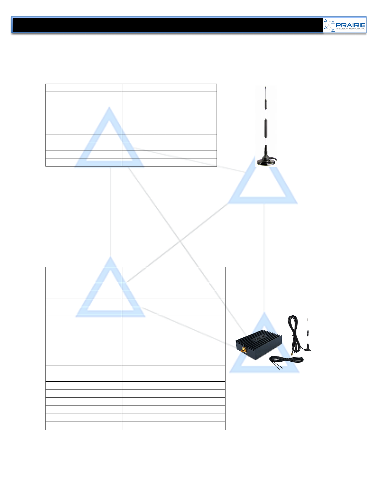
PPN High Gain Antenna
We carry a very good 5dBi high gain antenna that works very well at receiving even sparse cellular
signal. It is a Magnet Mount Antenna with a 14" Mast, 3" Magnet Base and Enclosed Coils with
FME Female Connector. Please check with your local PPN reseller for availability.
Antenna Gain
5dBi
Frequencies (MHz)
•
698-806 LTE
•
806-894 IDEN / HSPA+
•
1710-1755 AWS / LTE
•1850-1995 HSPA+
•2110-2155 AWS / LTE
VSWR
1.1483 to 1.9796
Input Impedance
50 ohm
Radiation
Omni-directional
Polarization
Vertical
PPN Cellular Amplifier
While there are many wireless cellular amplifiers on the market, for our purposes we want to use a
‘direct connect’ amplifier to reduce loss and latency when trying to boost low cellular coverage
areas.
Frequency
Uplink: 824-849/1850-1920 Mhz;
Downlink: 869-894/1930-1990Mhz
Input Impendance
50 ohm
Average Gain
19dB Cellular / 19 dB PCS
Maximum Gain
19dB
VSWR
<2:0
Standards Supported
•
CDMA/WCDMA
•GSM
•EDGE
•HSPA+
•EVDO
•
LTE
AC Power Transformer
Input: AC 100 -240V, 50-60 Hz
Output: 5 – 15V
DC Power
12V
Maximum RF Output
1 Watt EIRP
Noise Figure
5dB
Cable
RG58
Dimensions
4.72” x 2.72” x 0.98”
Weight
0.57 lbs
Table of contents


