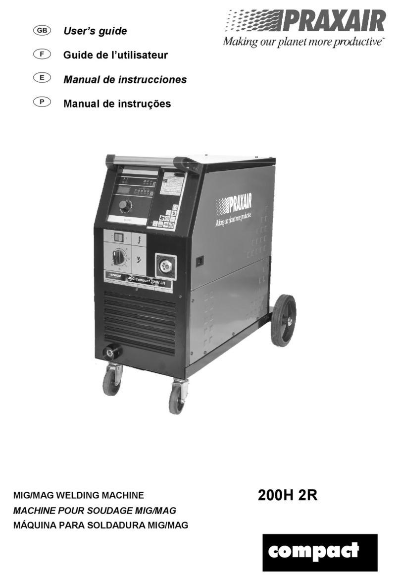
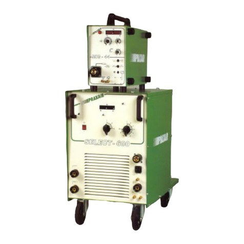
Praxair MIG COMPACT-220H/2R User manual

User’s guide
Guide de l’utilisateur
Manual de instrucciones
Manual de instruções
MIG/MAG WELDING MACHINE
MACHINE POUR SOUDAGE MIG/MAG
MÁQUINA PARA SOLDADURA MIG/MAG
MIG COMPACT-220H/2R
MIG COMPACT-250H/2R
MIG COMPACT-290H/2R
MIG COMPACT-300H/4R
MIG COMPACT-350H/4R
MIG COMPACT-400H/4R
MIT05390 Ed.05/2013

MIG COMPACT 220H/2R / 250H/2R / 290H/2R / 300H/4R / 350H/4R / 400H/4R
2
INDEX
English
1 - Safety instructions............................................................................................pag.3
2 - Mig/Mag welding …………………………………………………..............……….pag.4
2.1 - Description ................................................................................. pag.5
2.2 - Error messages …………………………………………………….. pag.8
3 - Technical data..................................................................................................pag.8
4 - Installation/Operating........................................................................................pag.10
5 - Electric schema................................................................................................pag.11
6 - Spare parts list..................................................................................................pag.15
7 - Maintenance.....................................................................................................pag.18
Français
1 - Instructions de Sécurité....................................................................................pag.19
2 - Soudage Mig/Mag ………………………………………………………………… pag.20
2.1 - Description …………………………………………………………pag.21
2.2 - Messages d’erreur ……………………………………………….. pag.24
3 - Caractéristiques................................................................................................pag.24
4 - Branchement / Mise en marche .......................................................................pag.26
5 - Schème électrique............................................................................................pag.27
6 - Nomenclature...................................................................................................pag.31
7 - Entretien...........................................................................................................pag.34
Español
1 - Instrucciones de Seguridad..............................................................................pag.35
2 – Soldadura Mig/Mag .........................................................................................pag.37
2.1 - Descripción …………………………………………………………… pag.38
2.3 - Mensajes de error …………………………………………………… pag 41
3 - Características……………………………………………..…………………….…. pag.41
4 - Instalación / Funcionamiento............................................................................pag.43
5 - Esquema Electrico............................................................................................pag.44
6- Lista de piezas...................................................................................................pag.48
7- Mantenimiento...................................................................................................pag.51
Português
1 - Instruções de Segurança..................................................................................pag.52
2 - Soldadura Mig/Mag ..........................................................................................pag.54
2.1 – Descrição ………………………………………………………….…..…….. pag.55
2.2 – Mensagens de erro …………………………………………………………. pag.58
3 - Características.................................................................................................. pag.58
4 - Instalação / Funcionamento ............................................................................. pag.60
5 - Esquemas Eléctricos........................................................................................ pag.61
6 - Lista de peças ................................................................................................. pag.65
7 - Manutenção ..................................................................................................... pag.68
We thank your preference for our mark. We continue building equipments that guarantee reliability and robustness.
This manual must be read and understood carefully. Do not install, operate or maintain this appliance before read this user's
manual. The equipment must be installed, operated or maintained only by qualified persons. Never start up this welding
rectifier without his casing. Before open, disconnect it from the main's socket.
Nous vous remercions d’avoir choisi notre marque. Nous continuons à construire des machines qui garantissent
précision et robustesse. Ce manuel d'instructions doit être lu et bien compris. Ne pas installer, mettre en service ou effectuer
des opérations d'entretien avant la lecture de ce manuel. Seules les personnes qualifiées doivent faire le raccordement au
réseau, des opérations de soudage ou l’entretien.
Le agradecemos su preferencia por nuestra marca. Continuamos construyendo equipamientos que garantizan
fiabilidad y robustez. Este Manual de Instrucciones debe ser leído y comprendido cuidadosamente. No se debe instalar,
poner en funcionamiento o efectuar mantenimiento antes de la lectura de este Manual de Instrucciones. Estos equipos de
soldadura solamente deben ser instalados, operados o reparados por personal debidamente calificado, para prevenir
averías y prolongar suya utilización.
Agradecemos a sua preferência pela nossa marca. Prosseguimos construindo equipamentos que garantam
fiabilidade e robustez. Este Manual de Instruções deve ser lido e compreendido cuidadosamente. Não se deve instalar, pôr
em funcionamento ou efectuar serviços de manutenção antes de ler o Manual de Instruções. Estes equipamentos de
soldadura só devem ser instalados, operados ou reparados por pessoal devidamente qualificado, para prevenir avarias e
prolongar a sua utilização.
P
F
E
GB

MIG COMPACT 220H/2R / 250H/2R / 290H/2R / 300H/4R / 350H/4R / 400H/4R
3
1 - SAFETY PRESCRIPTIONS FOR ARC WELDING GENERATORS
The Safety Prescriptions given in this manual do not replace but summarise the obligations for compliance with the current safety and accident-
prevention regulations. Before install, operate or maintain the welding equipment, read and understand carefully the current safety and accident-
prevention regulations.
In any case, the personnel involved in the use of the welding machine must be adequately trained with regard to use of the machine and
observance of the fundamental welding rules.
Setting up of the work area must comply with certain fundamental principles. Basic safety of persons and things depends on the observance of
these minimum requires.
1. Personal Protection
The skin or eyes burns resulting from the exposure to the electric arc welding radiations or metal fusion can bring more dangerous effects
than sunburn. Therefore:
a) Use a protection mask equipped with the respective inhatinic filter to protect the eyes, face, neck and ears from the projections and the arc
welding radiation. Prevent the persons near the welding places of the negative effects provoked by the arc welding radiations or metal fusion.
b) Use non-inflammable gloves, long sleeves shirt, trousers without folds, boots, welding mask, apron and hat to protect the hair. These
protections are needed to insure that the skin stays protected from the referred radiations.
Avoid using clothes with pockets or folds so that in case of occurring any projection of hot metal these will not deposit in the clothes’ folds or
pockets.
c) To protect the persons near the welding place, separations of non-inflammable curtains ought to be installed.
d) Always use safety glasses when standing in a place where metal projections can occur. Persons that circulate in the working area ought to use
safety glasses.
2. Preventing Fires
The projections can cause fires when in contact with combustible substances, liquids or gaseous. Therefore:
a) Every combustible material must stay far from the working place. When possible the combustible materials must be covered with non-
inflammable covers. These materials include wool, clothes, sawdust, natural gas, acetylene, propane and similar materials.
b) The metal projections can penetrate in wall or floor cracks causing non detectable latent fire. These cracks must be conveniently protected
from the metal fusion projections.
c) Welding, cutting or any kind of hot operation should not be made in recipients, deposits, tanks or other kind of used containers that haven’t
been carefully cleaned from substances that can produce toxic or inflammable vapours.
d) For protection against fire must exists a fire extinguisher system nearby, that can be used quickly like a water hose, a water recipient, sand or a
portable extinguisher.
e) Once the welding operations are concluded, the working area must be inspected to insure the absence of metal fusion projections that can
cause further fires.
3. Electric Discharge
Burns or mortal electrocution can be caused by 110 voltages or less. The gravity of this kind of discharges is determined by the intensity of
electric current that passes through the human body. Therefore:
a) Do not permit contact of the skin with metal pieces or even the use of wet or humid clothing. Wear only well dry gloves.
b) If it’s really needed to make welding operations in humid places the operators must wear very well dry gloves, rubber shoes or boots and
stepping the dry floor in order to be isolated from the electric current.
c) The welding machine must be connected to an electrical board equipped with an appropriate differential and earth connection. The earth
connection wire’s section must be correct according the norms about electric cables.
d) Do not use damaged welding cables. Do not overload the cable. Cable extensions or connections must be always correctly isolated.
e) The equipment must remain disconnected when not in use because an accidental electrical discharge can cause overheating and provoke a
fire. Do not roll the welding cable around the body.
f) The earth cable must be connected to the welding piece closest from the welding area. Welding current must passes through metallic elevations
or crane cables if long distance earth cable connections are made.
4. Ventilation
The smoke produced by the welding, mainly in closed spaces can provoke irritations if breathed during a long period of time.
a) Always take special care having proper ventilation in the welding places by the means of natural or forced ventilation systems. Do not weld
over zinc galvanised materials, cadmium, lead or beryllium, without prevent the needed ventilation to avoid smoke provoked by the welding of
these materials.
b) Do not weld near places containing chlorinated hydrocarbon vapours resultants from degreasing operations. Reactions can be provoked from
the vapours of dissolvents with the resultant heat of electric welding arc producing toxic or irritating gas.
c) Eye, nose or throat irritations during the welding process means that the ventilation system isn’t proper. In this case the ventilation should be
increased in the welding area. Stop the welding operation if the irritations persist.
5. Equipment maintenance
The quality of the welding process depends on the good condition of the welding equipment. To maintain it’s good condition and protect the
operator, maintenance reviews should be made periodically. If reviews aren’t made, accidents can occur due to fire or electric discharges.
Therefore:
a) The equipment installation and maintenance operations must be done by qualified personal. Do not proceed with electric repairs if you are not
properly qualified.
b) Before starting with any maintenance operation the welding equipment must be disconnect from the power supply.
c) The welding cables and the power supply cable and even the welding machine must be kept in good working conditions. This equipment must
never be used in less proper working conditions.
d) The welding equipment and its accessories must be treated carefully. Keep the machine far from heating sources, ovens or hothouses, from
humid places as water wells, oils or lubricants, from corrosive environments or intemperate weather.
e) Keep the safety systems and the chassis of the machine in proper working conditions.

MIG COMPACT 220H/2R / 250H/2R / 290H/2R / 300H/4R / 350H/4R / 400H/4R
4
f) Use the welding equipment only in jobs that are according to the equipment characteristics.
6. Using WELDING or GAS CUTTING equipment.
a) The operator of welding or gas cutting equipments must know the specific characteristics and the correct form of use.
b) The pressures ought to be according to the manufacture recommendations.
c) The welding torches, hoses and reducers must be kept well tightened with no leaks, cleaned and free from oils or lubricant greases.
d) The pressure reducers can not be submitted to sudden changes of pressure and must be used according to the manufacturer specifications.
Do not use an installation without being equipped with proper retention valves.
e) Periodical checks must be made to the installation for detection possible gas leaks or other defects. Qualified personnel must execute the
maintenance operations.
7. Handling of Gas Tubes
The user must know and follow the safety instructions for stocking, use and transportation of compressed, liquefied and dissolved gases
under pressure used in welding or cutting operations.
Besides the specified norms must follow those that concern the kind of welding process to be used (Electrode, Tig, Mig, Plasma,
Plasmacutting, Laser, etc.), as well as the specific characteristics of the equipment, the power supply conditions, hygiene norms and safety at
work and the machine’s safety regulations . The fulfilment of this safety norms, does not guarantee that the content is enough for all cases or
conditions, or invalids the fulfilment of current legal norms.
2 –Mig/Mag Welding
These semi-automatic arc welding machines under shield gas use inert gases like argon and mixed argon (MIG process -
Metal Inert Gas) or active gases as CO2 (MAG process - Metal Active Gas).
WELDING METAL SHIELD GAS
100% CO2 (Carbon dioxide)
80% Ár (Argon) + 20% CO2
Carbon steel 85% Ar +15% CO2
98% Ar + 2% CO2
Stainless steel 95% Ar + 5% CO2
Al Si (aluminium/silicon) 100% Ar
Al Mg (aluminium/magnesium) 100% Ar
CuSi (copper/silicon) 85% Ar + 15% He (Hélio)
Comparing with CO2, mixed Ar+CO2 has the advantage of increasing more stability to the welding arc with low spatters and a
better finishing of the welding pool. There are other gas moistures from helium to increase penetration or oxygen, etc for
specialized welding jobs. For these jobs, a consult to gas producers is advised.
CO2 seam
(earth plug nr. 1) Argon/CO2 seam
(penetration – earth Plug nr.2) Argon/CO2 seam
(filling – earth Plug nr. 3)
2 inductance positions
220 / 250 / 290 / 300 3 inductance positions 350 / 400

MIG COMPACT 220H/2R / 250H/2R / 290H/2R / 300H/4R / 350H/4R / 400H/4R
5
1
2
3
4
5
6
7
8
9
10
11
2.1 - Description
Machines suitable for arc welding under protective gas, using inert gases, such as argon and his mixtures ( MIG process -
metal inert gas ) or active gases such as CO2 ( MAG process - metal active gas ).
These machines are equipped with integrated wire feeder, with coil holder and 2 rolls motor (220, 250 and 290 models) or 4
rolls motor (300, 350 and 400 models) protected by a lateral door.
Front panel
1 – Welding parameter controller 7 – Earth plug nº 2 - mixgas (penetration)
2 – General switch 8 – Earth Plug nº1 - 100% CO2
3 – Voltage selector switch (regulation – 220/250/290/350/400) 9 – Push-pull mig torch connection (optional)
4 – Voltage selector switch (fine adjustment - 350/400) 10 – Wire feeder door
5 – Cooling air outlet 11 – Mig torch adaptor
6 – Earth plug nº 3 - mixgas (filling)
Rear panel
12 – Gas bottle bracing 16 – Input cable
13 – Gas inlet 17– Cooling air outlet
14 – Fuse 5A (input) 18 – Gas bottle holder
15 – Fuse 16A (wire feed motor)
12
13
14
15
18
16
17

MIG COMPACT 220H/2R / 250H/2R / 290H/2R / 300H/4R / 350H/4R / 400H/4R
6
2
3
4
1
5
I2
1
2
3
4
6
7
8
9
10
11
12
13
14
15
16
5
Wire feeder
1 – Key button “wire inch” – To manually positioning wire at the torch tip without gas and energy consumption.
2 – Key button “test gas” – To purge torch gas tubes and to allow the adjustment of gas flow on the flowmeter. Pushing key
button the gas flows; to interrupt gas flow release key button.
3 – Wire feed motor (2 rolls or 4 rolls)
4 – Wire coil
5 – Coil breakage system
Parameter controler
1 – Alarm – cooling water failure (models 300/350/400) 9 – 2T (2 times) torch mode indicator
2 – Alarm – Thermal surcharge 10 – 2T/4T/Spot selector
3 – Machine under voltage indicator 11 – Adjustable parameters selector
4 – Welding current indicator (models 300/350/400) 12 – Post-gas adjustment indicator
5 – Digital display 13 – Spot time adjustment indicator
6 – Adjustment parameter button 14 – Burn-back time adjustment indicator
7 – Spot welding time adjustment indicator 15 – Up-slope speed motor time adjustment indicator
8 – 4T (4 times) torch mode indicator 16 – Wire feed motor speed adjustment indicator
1 – Alarm – cooling water failure – (models 300/350/400) - When lighted unable machine running by low torch cooling
water pressure (cooled machines versions), to avoid damages by overheating.
2 – Alarm – thermal surcharge – When lighted unable machine running by thermal surcharge. The thermal sensor is
placed on the central main transformer coil.
3 – Machine under voltage – Indicates that machine is under input voltage.

MIG COMPACT 220H/2R / 250H/2R / 290H/2R / 300H/4R / 350H/4R / 400H/4R
7
4 – I2 – Welding current – Only models 300/350/400 – When lighted indicates that welding current is showed on the
digital display.
5 – Digital display – Shows the selected parameter value. During welding:
- the digital display indicates the value of welding current A - Ampere (on digit versions)
- when the button is rotated the digital display shows the wire motor speed m/min
- after this adjustment automatically turns to indicate the welding current value.
6 – Adjustment button – Adjusts the selected parameter value.
7 – Spot mode – When selected, indicates that machine is at spot welding mode, automatically interrupting the welding
at the end of the selected period.
8 – 4 times mode – When selected indicates that machine is on 4 times torch mode. Under extensive welding seams,
the operator can press and release torch trigger; the machine continues to welding. Press and release button to stop
welding.
9 – 2 times mode – When selected indicates that machine is under 2 times torch mode. To continuous welding torch
trigger must be always pressed.
10 – Mode 2T/4T/Spot welding selecting key button.
11 – Selecting key button – Selects to adjust post-gas, spot, burn-back and up-slope time parameter.
12 – Post-gas – When selected allows adjusting, between 0 and 10 seconds, the gas flow time after stop welding; this
protects the welding seam from oxidation and cools the torch.
13 – Spot time: When selected the welding spot time. After this time the machine automatically stops.
14 – Burn-back – When selected allows adjust, between 0 and 10 seconds by means of the adjusting button, the wire
length at the torch, at the end of welding. The burn-back time can be adjusted between 0,1 and 1 second.
15 – Up-slope motor speed – When selected allows adjust, by means of the adjusting button, the up-slope speed motor
time till reach the selected speed. It must be adjusted between 0,1 and 1 seconds.
16 – Wire speed – When selected allows adjust, by means of the adjusting button, the wire speed between 0 and 18
m/min. This parameter is continuous active; with machine running, it’s enough touch the button to adjust wire speed.
1st/2nd times
push/release
post-
gaz
3rd/4th times
push/release
Welding current
Gas flow
Torch trigger
Welding current
Gas flow
post-
gaz
Torch trigger
1st time / push trigger 2nd time - release trigger

MIG COMPACT 220H/2R / 250H/2R / 290H/2R / 300H/4R / 350H/4R / 400H/4R
8
19.0
1234567Pos.
Volt 22.1 25.8 29.7 33.0 36.6 40.3
Pos. 12345678910
Volt 16.5 18.5 20.5 22.5 24.5 26.5 28.5 31.5 34.0 37.0
2.2 – Error messages:
During machine running several error messages can be showed at the digital display:
Er 1
– Indicates that machine is automatically switched off by thermal surcharge due to exceeding of duty cycle. Machine must
cools to reset.
Er 2
– Indicates that machine is automatically switched off due to cooling fluid failure. Check:
- the regular functioning of fluid cooler.
- the level fluid of cooler tank.
- twists and bottlenecks of torch cooling tubes.
Er 3 -
Indicates that, when machine is switched on, the torch trigger is accidentally activated.
Er 4 –
Indicates that there are failures of communication between frontal and interface PCBoards. Electrical contacts failures
must be checked out. If necessary, PCBoards must be changed by qualified technician.
3 – TECHNICAL DATA
220 250
Voltage board Voltage board
Technical data 220
Current adjustment 7 positions
Wire diameters Ø 0.6 – 1.0 mm
Weight 54.5 Kg
Dimensions 75 x 46 x 74 cm
Technical data 250
Current adjustment 10 positions
Wire diameters Ø 0.6 – 1.0 mm
Weight 64 Kg
Dimensions 75 x 46 x 74 cm

MIG COMPACT 220H/2R / 250H/2R / 290H/2R / 300H/4R / 350H/4R / 400H/4R
9
Pos.
Volt
123456789101112
16.5 18.5 20.5 22.5 24.0 26.0 30.0 32.0 34.0 36.028.0 38.0 Pos.
Volt
123456789101112
16.5 18.5 20.5 22.5 24.0 26.0 30.0 32.0 34.0 36.028.0 38.0
A
B
C
D
17.0
17.4
17.7
18.1
18.7
19.3
19.7
20.1
20.7
21.3
21.9
22.3
22.7
23.3
24.0
24.6
25.8
27.0
27.7
28.4
29.4
30.7
32.1
32.8
33.7
35.1
36.5
38.0
1234567
Pos.
A
B
C
D
17.0
17.4
17.8
18.2
18.8
19.5
19.9
20.4
21.1
21.8
22.5
23.0
23.4
24.1
24.8
25.6
27.1
28.5
29.4
30.3
31.6
33.2
34.9
35.8
36.5
38.3
40.1
42.0
1234567
Pos.
290 300
Voltage board Voltage board
350 400
Voltage board Voltage board
Tecnical data 290
Current adjustment 12 positions
Wire diameters Ø 0.6 - 1.0 mm
Weight 68 Kg
Dimensions 75 x 46 x 74 cm
Tecnical data 300
Current adjustment 28 (7x4) positions
Wire diameters Ø 0.6 – 1.0 mm
Weight 70 Kg
Dimensions 88 x 59 x 86 cm
Tecnical data 350
Current adjustment 28 (7 x 4) positions
Wire diameters Ø 0.6 - 1.2 mm
Weight 102 Kg
Dimensions 88 x 59 x 86 cm
Tecnical data 400
Current adjustment 28 (7 x 4) positions
Wire diameters Ø 0.6 – 1.6 mm
Weight 108 Kg
Dimensions 88 x 59 x 86 cm

MIG COMPACT 220H/2R / 250H/2R / 290H/2R / 300H/4R / 350H/4R / 400H/4R
10
9
123 5
4
5
6
8
6
7
8
7
5
8
6
7
7
4 – INSTALATION / OPERATING
MIG machines must be installed in proper places free from dust, humidity and flammable products (see pag. 39 "SAFETY
PRESCRIPTIONS FOR ARC WELDING GENERATORS).
-Before connecting the primary cable to the mains supply, voltage must be checked (3x230 or 3x400 Volt). Normally, the
welding machine is settled to 3x400V. Under request it may be prepared to other voltages.
-The earth connection is strongly recommended to avoid health risks.
-When connecting the gas or water hoses it is recommendable to check eventual leaks.
-The torch, earth cable must be well tightened when connected to their plugs. Equal cares must be taken with the earth clamp
in order to maintain the good quality of the welding.
When positioning the wire coil on the coil holder (4-fig.1), it is necessary to verify the correct positioning of breaking hole (3-
fig.1) on the spindle (5-fig.1) of the holder (4-fig.1) in order to maintain the breakage system operationally.
- The wire feeder rolls (8-fig.2) and the tip of the torch (9) must correspond to the wire diameter.
The wire must be manually conducted a few centimeters through the rolls (8-fig.2) and the wire guide (7-fig.2). After this, close
the traction levers (6-fig.2) verifying that the correct positioning of the wire on the roll rend.
The roll pressure regulation must be completed when the motor is running (the wire must flow without sliding). This pressure
should be reduced to the minimum in order to prevent wire deformations by crushing.
- After this, the wire coil breakage system must be regulated, actuating on the respective screw (2-fig.1). The rotation
movement of the wire coil must stops at the same time as the motor.
- Switch on the machine and press the torch trigger (models 220/250/290) or the “wire inch” key button (models 300/350/400)
until the wire appears outside the torch tip (9-fig.3). If necessary, unscrew the tip torch and straight torch cable.
- Open gas bottle flowmeter and press the gas test key button. Gas must flow until complete elimination of the air of the torch.
After this, regulate the gas flow between 6 and 12 lts/min. During welding, revise gas flow.
- Machine is ready to weld. If necessary, before start the welding job, test welding parameters on a sample. Before welding,
analyze personal and environmental security conditions.
2 rolls motor 4 rolls motor
Fig.1
Fig.2 Fig.3

MIG COMPACT 220H/2R / 250H/2R / 290H/2R / 300H/4R / 350H/4R / 400H/4R
11
5 – ELECTRICAL SCHEMA (220 / 250 / 290 / 300) – 3x400V
A1 - Main switch A2 - Voltage selector switch (coarse adjustment)
A3 - Voltage selector switch (fine adjustment) CI - PCBoard
CT - Contactor EV - Solenoid valve
F1 - General fuse F3 - Wire motor fuse
M1 - Motor fan M2 - Wire feed motor
MS - Torch micro-switch PR - Rectifier bridge
SH - Shunt T1 - Main transformer
T2 - Auxiliary transformer T3 - Inductance
TºC - Thermal switch
A1
T2
P
0V 230V 400V
0V 26V
2/T1
4/T2
6/T3
1/L1
3/L2
5/L3
R
S
T
8
11
6
CT
5
W
V
U
F1-2A
8
11 15
F3-10/16A
12
CT
M2
2
1
C.I. (mig serie 6 digit)
A2A1
13
1234
876 5
12
1234
J5 J3
J4
MS
2223
wire inch
2120
17
16
14
17
test gas
1918
19
T1
TºC
3
220
250
290/300
220
250
290/300
250
290/300
4
T
S
R
U
V
W
U
W
V
18
20 21
910
14
13
10
12
12
J1
15 9
22
23
34
10
9
7
(Exception model Basic)
U1
2
V2
3
W3
1

MIG COMPACT 220H/2R / 250H/2R / 290H/2R / 300H/4R / 350H/4R / 400H/4R
12
ELECTRICAL SCHEMA 220 / 250 / 290 / 300 (3x230/400V)
A1 - Main switch A2 - Voltage selector switch (coarse adjustment)
A3 - Voltage selector switch (fine adjustment) CI - PCBoard
CT - Contactor EV - Solenoid valve
F1 - General fuse F3 - Wire motor fuse
M1 - Motor fan M2 - Wire feed motor
MS - Torch micro-switch PR - Rectifier bridge
SH - Shunt T1 - Main transformer
T2 - Auxiliary transformer T3 - Inductance
TºC - Thermal switch
RS
400 V
RS
230V
voltage selector
T
T
A1
T1
T2
0V 230V 400V
0V 26V
TºC
2/T1
4/T2
6/T3
1/L1
3/L2
5/L3
3
220
250
290/300
220
250
290/300
6
7
4
CT
5
W
V
U
F1-2A
8+
T
S
R
P
PB
8+7+ 8
R
T
S
UVW
8
R
CT
EV
M2
2
1
A2A1
13
1234
876 512
12
3
4
J5 J3
J4
MS
wire inch
2120
17
16
14
17
test gas
1918
19
18
20 21
910
14
13
12
12
J1
15 9
22
23
34
10
9
11
F3-10/16A
12
11 10 15
2223
U
V
W
U
W
V
T
S
220
250
290/300
(Exception modelo Basic)
U1
2
V2
3
W3
1
C.I. (mig serie 6 digit)

MIG COMPACT 220H/2R / 250H/2R / 290H/2R / 300H/4R / 350H/4R / 400H/4R
13
ELECTRICAL SCHEMA 350 / 400 (3x400V)
A1 - Main switch A2 - Voltage selector switch (coarse adjustment)
A3 - Voltage selector switch (fine adjustment) CI - PCBoard
CT - Contactor EV - Solenoid valve
F1 - General fuse F3 - Wire motor fuse
M1 - Motor fan M2 - Wire feed motor
MS - Torch micro-switch PR - Rectifier bridge
SH - Shunt T1 - Main transformer
T2 - Auxiliary transformer T3 - Inductance
TºC - Thermal switch
T1
T2
0V 230V 400V
0V 26V
TºC
2/T1
4/T2
6/T3
1/L1
3/L2
5/L3
3
4
CT
W
V
U
8
W
U
CT
M2
2
1
CI Frontal
A2A1
13
1234
876 512
1234
J5 J3
J4
MS
wire inch
2120
17
16
14
17
test gas
1918
19
18
20 21
910
14
13
12
12
J1
15 9
22
23
3
4
10
9
11
F3-10/16A
12
11 10 15
2223
U
V
W
U
W
V
R
S
T
P
5
A1
6
F1-2A
7
A2 (T)
VA2 (S)
A2 (R)
A3 (S)
A3 (T)
A3 (R)
8
5

MIG COMPACT 220H/2R / 250H/2R / 290H/2R / 300H/4R / 350H/4R / 400H/4R
14
ELECTRICAL SCHEMA 350 / 400 (3x230/400V)
A1 - Main switch A2 - Voltage selector switch (coarse adjustment)
A3 - Voltage selector switch (fine adjustment) CI - PCBoard
CT - Contactor EV - Solenoid valve
F1 - General fuse F3 - Wire motor fuse
M1 - Motor fan M2 - Wire feed motor
MS - Torch micro-switch PR - Rectifier bridge
SH - Shunt T1 - Main transformer
T2 - Auxiliary transformer T3 - Inductance
TºC - Thermal switch
RS
400 V
RS
230V
voltage selector
T
T
A1
T1
T2
0V 230V 400V
0V 26V
TºC
2/T1
4/T2
6/T3
1/L1
3/L2
5/L3
3
6
7
4
CT
5
W
V
U
F1-2A
8+
P
PB
8+7+ 8
R
T
S
XYZ
8
R
CT
M2
2
1
C.I. Frontal
A2A1
13
1234
876 512
1234
J5 J3
J4
MS
wire inch
2120
17
16
14
17
test gas
1918
19
18
20 21
910
14
13
12
12
J1
15 9
22
23
3
4
10
9
11
F3-10/16A
12
11 10 15
2223
U
V
W
U
V
T
S
V
W
W
U
A2 (T)
VA2 (S)
A2 (R)
A3 (S)
A3 (T)
A3 (R)
X
Y
Z
7+

MIG COMPACT 220H/2R / 250H/2R / 290H/2R / 300H/4R / 350H/4R / 400H/4R
15
6 – SPARE PARTS LIST 220 / 250 / 290 / 300 / 350 / 400
1
2
3
4
5
7
8
9
10
11
12
13
14
15
17
18
19
20
21
22
25
26
27
28
16
24
23

MIG COMPACT 220H/2R / 250H/2R / 290H/2R / 300H/4R / 350H/4R / 400H/4R
16
Codes
Nr Description 220 250 290 300 350 400
1 Flexible sticker panel PF105013 PF105013 PF105013 PF105014 PF105014 PF105014
2 Right/left handle PF104823 PF104823 PF104823 PF104823 PF104825 PF104825
3 Button CO102616 CO102616 CO102616 CO102616 CO102616 CO102616
4 Torch connector CO105021 CO105021 CO105021 CO105021 CO105021 CO105021
5 Main switch CO0DB2A321622S1Q CO0DB2A321622S1Q CO0DB2A321622S1Q CO0DB2A321622S1Q CO0DB2A321622S1Q CO0DB2A321622S1Q
7 Quick plug CO9NSF05050 CO9NSF05050 CO9NSF05050 CO105021 CO105021 CO105021
8 Castor CO8WP08011126 CO8WP08011126 CO8WP08011126 CO8WR125155036 CO8WR125155036 CO8WR125155036
9 Wire holder CO104292 CO104292 CO104292 CO104292 CO104292 CO104292
10 Wire feed motor cpl
(see following pages)
CO8JR024401SFP CO8JR024401SFP CO8JR024401SFP CO104500 CO104500 CO104500
Main transformer PFK3102097 PFK3105023023405 PFK3105028023405 PFK3105028023405 PF101802 PF103065
Coil trio U/V/W PF102096 PFB14CT1E052302S PFB14CT1E052802S PFB14CT1E052802S PF101803 PF103066
11
Repair coil PFL911ECO2450000 PF101095 PF100875 PF100875 PF104549 PF100610
12 Inductance PF104423 PF104424 PF104424 PF104424 PF104425 PF104425
13 Fan CO8JV230100ELV CO8JV230100ELV CO8JV230100ELV CO8JV230100ELV CO8JV230340ELV CO8JV230340ELV
14 Wheel CO8VE2002044 CO8VE2002044 CO8VE2002044 CO8VN2002058 CO8VN2002058 CO8VN2002058
15 Control PCBoard PF105009 PF105009 PF105009 PF105007 PF105007 PF105007
16 Contactor CO0E305512024AC3 CO0E305512024AC3 CO0E305512024AC3 CO0E305512024AC3 CO0E311025024AC3 CO0E311025024AC3
17 Auxiliary transformer CO0TA4041500 CO0TA4041500 CO0TA4041500 CO0TA4041500 CO0TA4123000 CO0TA4123000
18 Gas connection CO101329 CO101329 CO101329 CO101329 CO101329 CO101329
19
Fuse holder
Fuse 2A
Fuse 5A
Fuse 10A
Fuse 16A
CO0Z1M063
CO0H1502002000RP
CO0H1502010000RP
CO0Z1M063
CO0H1502002000RP
CO0H1502010000RP
CO0Z1M063
CO0H1502002000RP
CO0H1502010000RP
CO0Z1M063
CO0H1502002000RP
CO0H1502010000RP
CO0Z1M063
CO0H1502005000RP
CO0H1502016000RP
CO0Z1M063
CO0H1502005000RP
CO0H1502016000RP
20 Security chain PFD2SAS40X16407 PFD2SAS40X16407 PFD2SAS40X16407 PFD2SAS40X16407 PFD2SAS40X16407 PFD2SAS40X16407
21 Cable holder CO7IR0000 CO7IR0000 CO7IR0000 CO7IR0000 CO7IR0000 CO7IR0000
22 Input cable PFB4A108190234S PFB4A108190234S PFB4A108190234S PFB4A108190234S PF103387 PF103387
23 Coarse voltage selector CO0B203M07 CO0B2M610 CO0B203M12 CO0B203M12 CO103154 CO103154
24 Fine voltage selector ------------- ------------- ------------ ------------ CO0B323M04 CO0B323M04
25 PVC deflector PF100326 PF100326 PF100326 PF100327 PF100327 PF100327
26 Shunt ------------ ------------- ------------ CO8Y2500120 CO8Y3000120 CO8Y4000125
27 Rectifier bridge CO1JT01600D0P00 CO1JT02000D0P00 CO1JT02400D0P00 CO1JT02400D0P00 CO1JT02900D0P00 CO1JT03500D0P00
28 Casing
Front panel
Rear panel
Gas bottle holder
Upper cover
Upper left cover
Lower left cover
Lower right cover
Mobile cover
PF104604
PF104607
PFL2295S0000
PF104645
PF104616
PF104614
PF104613
PF104615
PF104604
PF104607
PFL2295S0000
PF104645
PF104616
PF104614
PF104613
PF104615
PF104604
PF104607
PFL2295S0000
PF104645
PF104616
PF104614
PF104613
PF104615
PF104733
PF104729
PFL2295S0000
PF104646
PF104644
PF104642
PF104641
PF104643
PF104633
PF104637
PFL2295S0000
PF104646
PF104644
PF104642
PF104641
PF104643
PF104633
PF104637
PFL2295S0000
PF104646
PF104644
PF104642
PF104641
PF104643
Accessoires kit
Gas hose
Earth cable
MP101607
PF101737
MP101607
PF101737
MP101607
PF101738
MP101607
PF101738
MP101607
PFB4M105300234S
MP101607
PFB4M105300234S

MIG COMPACT 220H/2R / 250H/2R / 290H/2R / 300H/4R / 350H/4R / 400H/4R
17
2 rolls motor (220/250/290):
Nr. Description
1 2R Board
2 Axe
3 Traction
4 Spring
6 Pressure ajustment screw
8 24V/50W motor
Roll 0,8/1,0 mm
10 Roll 1,0/1,2 mm
11 Roll screw
12 Inlet wire guide
4 rolls motor (300/350/400):
Nr. Description
1 Board 4R
2 Axe
3 Axe
4,3,10 Traction lever
6,7,8,9 Bearing axe cpl.
12 Pressure adjustment screw
19 Central wire guide
21 Roll wheel
Roll 0,8/1,0 mm
Roll 1,0/1,2 mm
22 Roll 1,2/1,6 mm
23, 24 Protection cover cpl.
25,26,27,28 Torch connection cpl.
29 Inlet wire guide
30 24V/75W motor
32,33 Central wheel

MIG COMPACT 220H/2R / 250H/2R / 290H/2R / 300H/4R / 350H/4R / 400H/4R
18
7 – MAINTENANCE
MIG machines do not need special cares of maintenance, however, it is recommended a periodically inspecting and cleaning
operation. The frequency of this operation must be in according to the environment values of dust or humidity. It must be made as
follows:
- Disconnect the machine from the mains supply.
- Remove lateral covers.
- Clean all dust or humidity with a low pressure and dry air flow.
- Well retighten all electrical contacts (bolts and nuts).
- Also the torch must be periodically inspected. During operation it is subjected to high temperatures. To obtain more
information about torch maintenance it is recommended to read the respective user's manual.
IMPORTANT!
DO NOT INSTALL, OPERATE OR MAINTAIN THIS APPLIANCE BEFORE READ THIS USER'S GUIDE.
THE EQUIPMENT MUST BE INSTALLED, OPERATED OR MAINTAINED ONLY BY QUALIFIED PERSONS.
DAMAGE CAUSE PROCEEDING
The machine does not weld when
connected the main switch. Failure on main voltage Check main supply voltage and protective
electrical circuits.
Blown command circuit fuses. Check and replace, if necessary.
Interruption of the primary cable. Check and replace, if necessary
Irregular advance of wire Low pressure of rolls. Adjust the pressure system.
Wire guide damaged or in bad condition. Clean properly and replace, if necessary.
Diameter rolls do not match with wire
diameter. Replace rolls with the adequate diameter.
Wire coil breakage system too much
tightened. Adjust with the adequate pressure
Damaged wire or wire coil. Check and replace, if necessary.
Porosity in welding melt. Gas failure Check the bottle pressure and control de gas
flow.
Solenoid valve blocked Check and, if necessary, disassemble for
cleaning.
Too much wind blowing through the welding
zone. Protect the welding zone from wind or adjust up
the gas flow.
Torch nozzle blocked or in bad condition. Clean or replace the torch nozzle.
Welding piece too dirty, wet or greased. Clean the welding surfaces.
Failure on the welding quality. Defective electrical contact of earth clamp or
torch. Well tighten the earth clamp and torch. Check
the earth cable.
Failure on electrical contactor. Disassemble and clean electrical contactor. If
not possible, replace contactor.
Damaged rectifier bridge. Check bridge and replace, if necessary.
The wire feed motor do not run. Failure of the wire feed motor electrical supply. Check and replace, if necessary the wire feed
motor fuse. Check the electrical insulating of the
wire feed motor.
Failure of wire feed motor brushes. Replace brushes.

MIG COMPACT 220H/2R / 250H/2R / 290H/2R / 300H/4R / 350H/4R / 400H/4R
19
1 - INSTRUCTIONS DE SÉCURITÉ POUR LES EQUIPEMENTS DE SOUDAGE
Ces précautions sont destinées à protéger les utilisateurs d’appareils de soudage et leur respect peut éviter des lésions irrécupérables. Avant
de raccorder, mettre en marche ou opérer les postes de soudage il est impératif de lire et de respecter scrupuleusement les précautions et
normes de sécurité propres du produit.
SECURITE ELECTRIQUE
BRANCHEMENT SUR LE RESEAU DES SOURCES DE COURANT DE SOUDAGE
Avant raccorder votre appareil, vos devez vérifier que :
- Le compteur, le dispositif de protection contre les surtensions et l’installation électrique, soient compatibles avec la puissance maximale et la
tension d’alimentation (c.f. les plaques signalétiques).
- Le branchement, monophasé ou triphasé avec la terre soit réalisable sur un socle compatible avec la prise de son câble de liaison.
- Si le câble est branché à un poste fixe, la terre, si elle est prévue, ne doit jamais être coupée par le dispositif de protection contre les
choques électriques.
- Son interrupteur, s’il existe, soit sur la position “ARRET”.
POSTE DE TRAVAIL
La mise en ouvre du soudage à l’arc implique le strict respect des conditions de sécurité vis-à-vis des courants électriques:
- Assurez-vous qu’aucune pièce métallique accessible aux soudeurs et à leurs aides ne puisse entrer en contact direct ou indirect avec un
conducteur de phase et le neutre du réseau d’alimentation.
- Reliez à un seul point toutes les masses métalliques de l’installation qui se trouvent à portée de l’utilisateur. Ce point sera relié à la terre. -
Toutes ces liaisons devront être faites avec des câbles de section au moins équivalents à ceux du plus gros câble de phase.
- Lorsque les travaux de soudage doivent être effectués dans une enceinte dans laquelle l’operateur manque d’aisance, des précautions
supplémentaires doivent être prise et notamment:
- Le renforcement de la protection individuelle.
- L’isolation complète du porte-électrodes.
- Le maintien de l’appareil de soudage à l’extérieur de l’enceinte et, en cas d’impossibilité, l’isolation des parties de l’appareillage de soudage
en basse tension et la fixation par soudure de câble de mise à la terre de la pièce à souder.
INTERVENTIONS
Avant toutes vérifications internes et réparations, vous devez vous assurer que l’appareil est séparé de l’installation électrique par
consignation et condamnation :
- La prise de courant est débranchée. Les dispositifs sont conçus pour empêcher le branchement accidentel de la prise sur un socle.
- Le branchement accidentel du câble d’une installation fixe est rendu impossible.
- La coupure par l’intermédiaire d’un dispositif de raccordement fixe est omnipolaire (phase et neutre). Il est en position “ARRET” et ne peut
être mise en service accidentellement.
- Certains appareils sont munis d’un circuit d’amorçage HT.HF (Haute tension. Haute fréquence) signalé par une plaque. Vous ne devez
jamais intervenir à l’intérieur du coffret correspondant.
- Les interventions faites sur les installations électriques doivent être confiées à des personnes qualifiées pour les effectuer.
DEVIDOIRS DE FILS (procédé MIG MAG - TIG automatique)
Avant d’intervenir sur le dévidoir (changement de bobine, coincement de fil ...) coupez le courant lorsque cela est possible.
Dans le cas contraire et notamment lors de la mise en place du fil, assurez-vous que le fil où la torche ne risquent pas d’entrer en contact
avec des parties métalliques. N’oubliez pas de porter des gants.
ENTRETIEN
- Vous devez vérifier régulièrement le bon état d’isolement et les raccordements des appareils et accessoires électriques: prises, pinces de
pièces, porte-électrodes ou torches, câbles souples, gaines, conducteurs, prolongateurs ...
- Les travaux d’entretien et de réparation des enveloppes et gaines isolantes ne doivent pas être des opérations improvisées.
Faites :
- Réparer par un spécialiste où mieux, remplacer les accessoires défectueux.
- Vérifier périodiquement le bon serrage et le non-échauffement des connections électriques.
PROTECTION INDIVIDUELLE RISQUES D’ATTEINTES EXTERNES ENSEMBLE DU CORPS HUMAIN
- L’opérateur doit être habillé et protégé en fonction des contraintes de son travail.
- Faites en sorte qu’aucune partie du corps des opérateurs et de leurs aides ne puissent entrer en contact avec des pièces et parties
métalliques qui sont sous tension ou qui pourraient s’y trouver accidentellement.
- L’opérateur doit toujours porter des gants de cuir à manchettes.
- Les équipements de protection portés par l’opérateur et ses aides : gants, tabliers, chaussures de sécurité offrent l’avantage supplémentaire
de les protéger contre les brûlures des pièces chaudes, des projections et scories.
- Assurez-vous également du bon état de ces équipements et renouvelez-les
avant de ne plus être protégé.
LE VISAGE ET LES YEUX
Il est indispensable de vous protéger :
- Les yeux contre les coups d’arc (éblouissement de l’arc en lumière visible et
les rayonnements infrarouges et ultraviolets).
- Les cheveux et le visage contre les projections.
- Le masque de soudage, avec ou sans casque, doit toujours être muni d’un
filtre protecteur dont l’échelon dépend de l’intensité du courant de l’arc de
soudage.
- Le filtre coloré peut être protégé des chocs et projections par un verre
transparent situé sur la face avant du masque.
En cas de remplacement du filtre, vous devez conserver les mêmes
références (numéro de l’échelon d’opacité).
Les personnes à proximité du soudeur et à fortiori ses aides, doivent être
protégées par l’interposition d’écrans adaptés, de lunettes de protection anti-UV
et, si besoin, par un masque munie du filtre protecteur adapté.
Numero d'échelon (1) et utilisation recommandée pour le soudage à l'arc
Procedé de soudage
ou techniques connexes
Intensité du courant en Ampere
0,5 2,5 10 20 40 80 175 225 275 350 450
1 5 15 30 60 100 150 200 300 400 500
910 11 12 13 14
11 12 13 14
11 12 13 14 15
91011 12 13 14
10 11 12 13 14 15
10 11 12 13 14 15
910111213
Electrodes enrobés
0,5 2,5 10 20 40 80 175 225 275 350 450
1 5 15 30 60 100 150 200 300 400 500
125
MIG sur metaux lourds (2)
MIG sur alliages légers
TIG sur tous metaux
et alliages
MAG
Gougeage air/arc
Coupage au jet de plasma
Soudage plasma
10
10
125 250
250
(1) - Selons les conditions d'utilisation, le numero d'échelon immediatement inferieur peuvent être utilisés
(2) - L'expression "metaux lourds" couvre les aciers, les aciers alliés, le cuivre et ses alliages, etc.

MIG COMPACT 220H/2R / 250H/2R / 290H/2R / 300H/4R / 350H/4R / 400H/4R
20
RISQUES D’ATTEINTES EXTERNES
SECURITÉ CONTRE LES FUMÉES ET LES VAPEURS, GAZ NOCIFS ET TOXIQUES
Les opérations de soudage à l’arc avec électrodes doivent être exécutées sur des emplacements convenablement aérés.
- Les fumées de soudage émises dans les ateliers doivent être captées au fur et à mesure de leur protection, au plus prés possible de leur
émission et le mieux possible, et évacuées directement à l’extérieur. Si vous êtes dans cette situation, vous devez vous équiper en conséquence.
- Les solvants chlorés et leurs vapeurs, même éloignés, s’ils sont concernés par les rayonnements de l’arc, se transforment en gaz toxiques.
SECURITÉ D’EMPLOI DES GAZ (SOUDAGE SOUS GAZ INERTE TIG ET MIG)
STOCKAGE SOUS FORME COMPRIMÉ EN BOUTEILLES
Obéissez aux consignes de sécurité données par le fournisseur de gaz et en particulier :
- Evitez les choc: arrimez les bouteilles, épargnez leur les coups.
- Evitez les chaleurs excessives (supérieures à 50ºC).
DETENDEUR
Assurez-vous que la vis de détente est desserrée avant le branchement du tube de gaz à la bouteille.
Vérifiez bien le serrage du raccord de liaison avant d’ouvrir le robinet de bouteille. En cas de fuite, ne desserrez jamais un raccord sous
pression; fermez, d’abord, le robinet de la bouteille.
Utiliser toujours des tuyauteries souples et en bon état.
2 – SOUDAGE MIG/MAG
Machines á soudage MIG semi-automatique á l'arc sous protection gazeuse, avec utilisation de gaz inertes, comme l’argon et
ses mélanges (procédé MIG - métal inerte gaz) ou de gaz actifs comme le CO2 (procédé MAG - métal active gaz).
METAL A SOUDER GAZ DE PROTECTION
100% CO2 (Dioxyde de carbone)
80% Ar. (Argon) + 20% CO2
Acier doux (fer) 85% Ar +15% CO2
98% Ar + 2% CO2
Acier inoxydable 95% Ar + 5% CO2
Al Si (aluminium/silicium) 100% Ar
Al Mg (alumínium/magnésium) 100% Ar
CuSi (cuivre/silicium) 85% Ar + 15% He (Hélium)
L’utilisation du mélange Air + CO2 permet souder avec un arc plus stable, sans projections et avec une meilleure qualité du
cordon de soudage. Il existe aussi d'autres mélanges de gaz de soudage au hélium, oxygène, etc. pour des soudages
spécialisées. Pour plus de renseignements, consultez les fabricants de gaz.
2.1 – Description
Ces machines sont équipées de dévidoir de fils intégré, avec porte-bobines et moteur réducteur à 2 galets (modèles 220, 250
et 290) ou à 4 galets (modèles 300, 350 et 400) accessibles par une porte latérale.
Cordon soudé avec CO2
(Prise de masse nº 1) Cordon soudé avec Argon/CO2
(Pénétration – prise de masse nº2) Cordon soudé avec Argon/CO2
(Remplissage – prise de masse nº 3)
2 positions d’inductance
220 / 250 / 290 / 300 3 positions d’inductance
350 / 400
This manual suits for next models
5
Table of contents
Other Praxair Welding System manuals
Popular Welding System manuals by other brands

ESAB
ESAB LTR 160 Service manual

Chicago Electric
Chicago Electric 68888 owner's manual

GYS
GYS EXAGON 400 FLEX CC/CV manual

Polyvance
Polyvance 6049-C Nitro Fuzer Lite quick start guide

EWM
EWM Taurus 451 Basic S FDG/FDW operating instructions

Lincoln Electric
Lincoln Electric POWER-ARC SVM103-C Service manual