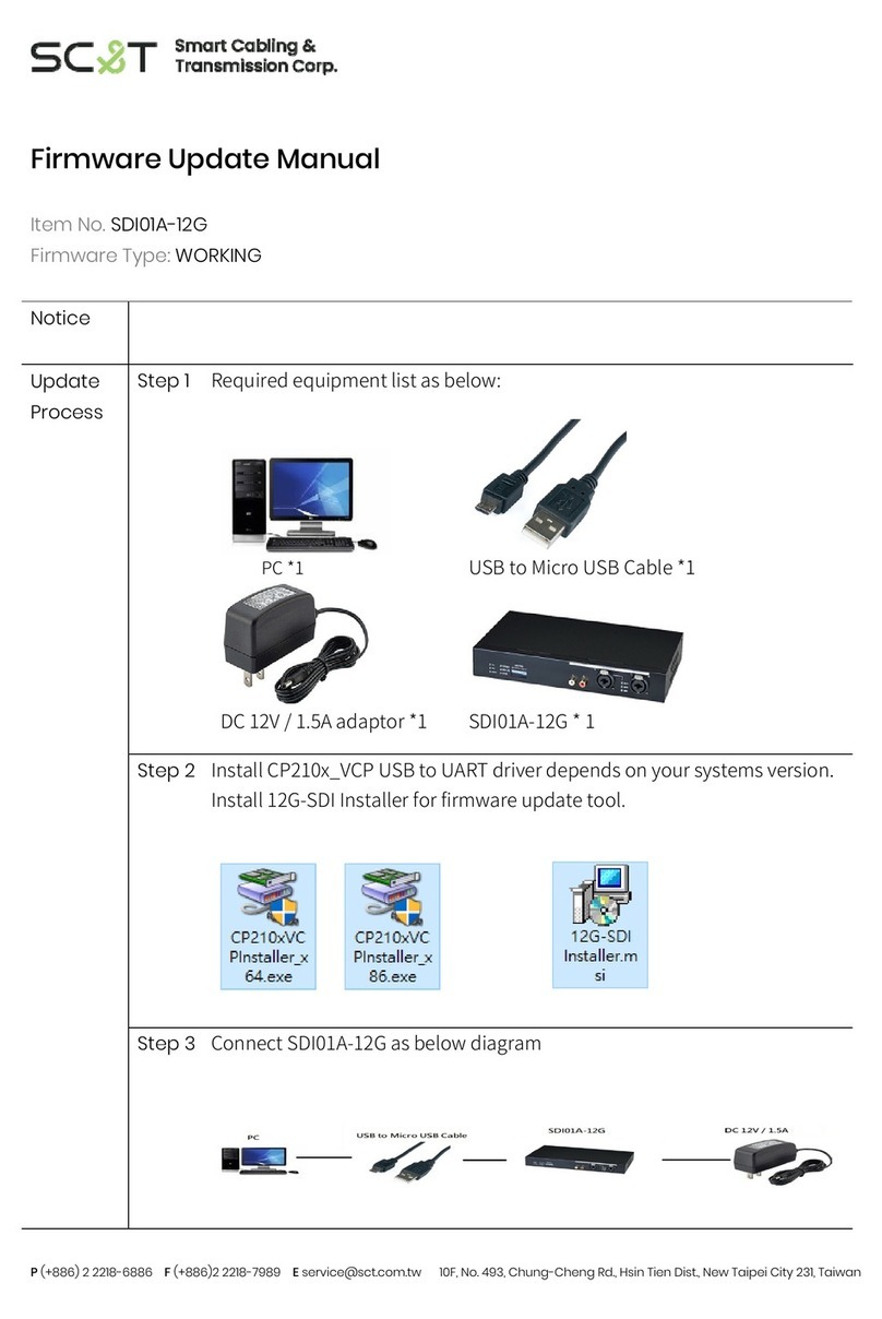
AudioCodes Mediant 2600B Assembly instructions

Hardware Installation Manual
AudioCodes One Voice™ for Microsoft Skype for Business
Mediant 2600B
Survivable Branch Appliance (SBA)
for Skype for Business


Survivable Branch Appliance 3 Mediant 2600B SBA
Hardware Installation Manual Contents
Table of Contents
1Introduction .......................................................................................................11
2Unpacking the Device .......................................................................................13
3Physical Description.........................................................................................15
3.1 Physical Dimensions and Operating Environment ................................................15
3.2 Front Panel Description ........................................................................................16
3.2.1 Module Slot Assignment ..........................................................................................17
3.2.2 SBA CPU Module ....................................................................................................18
3.2.2.1 Port Description........................................................................................18
3.2.2.2 LED Description .......................................................................................19
3.2.3 Media Processing (MPM) Module ...........................................................................20
3.2.4 OSN Server Modules...............................................................................................22
3.2.4.1 OSN4 Module...........................................................................................22
3.2.4.2 HDMX Module ..........................................................................................25
3.2.5 Fan Tray Module......................................................................................................26
3.3 Rear Panel Description.........................................................................................27
3.3.1 Power Supply Modules ............................................................................................28
4Mounting the Device .........................................................................................29
4.1 Desktop Mounting ................................................................................................29
4.2 19-Inch Rack Mounting.........................................................................................30
4.2.1 Mounting in a 19-inch Rack using Pre-Installed Rack Shelf....................................31
4.2.2 Mounting in a 19-inch Rack using Front and Rear Brackets ...................................32
5Cabling the Device ............................................................................................37
5.1 Connecting the Ethernet Ports to the LAN ............................................................38
5.1.1 Deployment of a Standalone Device .......................................................................39
5.1.2 Deployment of Two Devices for High Availability ....................................................40
5.2 Connecting the Serial Interface to a Computer .....................................................41
5.3 Connecting the OSN Server .................................................................................42
5.3.1 Cabling for Installing Operating System ..................................................................42
5.3.2 Cabling for Initial Installation of Third-Party Applications ........................................44
5.3.3 Cabling for Remote Connectivity (Post-Initial Setup) ..............................................45
5.4 Connecting to Power ............................................................................................46
6Hardware Maintenance .....................................................................................49
6.1 Preventing Electrostatic Discharge Damage.........................................................49
6.2 Replacing the SBA CPU Module ..........................................................................50
6.3 Installing the MPM Modules..................................................................................52
6.4 Installing the OSN Server Modules.......................................................................54
6.5 Replacing the Fan Tray Modules ..........................................................................56
6.6 Replacing the Power Supply Modules ..................................................................58

Hardware Installation Manual 4 Document #: LTRT-39392
Mediant 2600B SBA
List of Figures
Figure 3-1: Front Panel .......................................................................................................................... 16
Figure 3-2: Module Slot Assignment on Front Panel............................................................................. 17
Figure 3-3: SBA CPU Module................................................................................................................ 18
Figure 3-4: SBA CPU Module Ports ...................................................................................................... 18
Figure 3-5: SBA CPU Module LEDs ...................................................................................................... 19
Figure 3-6: MPM LEDs (e.g. MPM12B) ................................................................................................. 21
Figure 3-7: OSN4 Module Ports ............................................................................................................ 22
Figure 3-8: OSN4 Module LEDs ............................................................................................................ 24
Figure 3-9: HDMX Module LEDs ........................................................................................................... 25
Figure 3-10: Fan Tray Modules (FAN 1 and FAN 2) ............................................................................. 26
Figure 3-11: Rear Panel......................................................................................................................... 27
Figure 3-12: Power Supply Module ....................................................................................................... 28
Figure 4-1: Rubber Feet Locations ........................................................................................................ 29
Figure 4-2: Attaching Front-Mounting Brackets to Chassis ................................................................... 31
Figure 4-3: Rear-Mounting Brackets Attached to Rear-Rack Posts (60 cm)......................................... 33
Figure 4-4: Rear-Mounting Brackets Attached to Rear-Rack Posts (80 cm)......................................... 33
Figure 4-5: Attaching Rear-Mounting Flange to Chassis' Rear-Side Mounting Holes (60 cm) ............. 34
Figure 4-6: Attaching Rear-Mounting Flange to Chassis' Rear-Side Mounting Holes (80 cm) ............. 34
Figure 4-7: Sliding the Rear-Mounting Flanges into the Rear-Mounting Brackets (60 cm)................... 34
Figure 4-8: Sliding the Rear-Mounting Flanges into the Rear-Mounting Brackets (80 cm)................... 34
Figure 4-9: Fastening Rear-Mounting Flange to Rear-Mounting Bracket (60 cm) ................................ 35
Figure 4-10: Fastening Rear-Mounting Flange to Rear-Mounting Bracket (80 cm) .............................. 35
Figure 4-11: Front-Mounting Brackets Flush and Aligned with Front-Rack Posts (60 cm) ................... 36
Figure 4-12: Front-Mounting Brackets Flush and Aligned with Front-Rack Posts (80 cm) ................... 36
Figure 5-1: Connecting the LAN Interface ............................................................................................. 38
Figure 5-2: Default Ethernet Groups...................................................................................................... 39
Figure 5-3: Cabling for 1+1 Ethernet-Port Redundancy (Example)....................................................... 40
Figure 5-4: Cabling for High Availability (Example) ............................................................................... 40
Figure 5-5: Serial Interface Cable Adapter and Connector Pinouts ...................................................... 41
Figure 5-6: Connecting the Serial Interface ........................................................................................... 41
Figure 5-7: Cabling OSN4 Module for Installing Operating System ...................................................... 43
Figure 5-8: Cabling OSN4 Module for Serial Communication ............................................................... 44
Figure 5-9: Cabling OSN4 Module to Network ...................................................................................... 45
Figure 5-10: Connecting to Power ......................................................................................................... 47
Figure 6-1: Connecting ESD Wrist Strap to Chassis ESD Lug.............................................................. 49
Figure 6-2: Module Handle Partially Pulled Out (Top View) .................................................................. 50
Figure 6-3: SBA CPU Module Pulled out of Slot (Top View) ................................................................. 50
Figure 6-4: Inserting SBA CPU Module ................................................................................................. 51
Figure 6-5: Extracting Blank AMC Modules (Top View) ........................................................................ 52
Figure 6-6: Inserting MPM Module ........................................................................................................ 53
Figure 6-7: Extracting Blank AMC Modules from Slots for OSN Server (Top View) ............................. 54
Figure 6-8: Inserting OSN Module ......................................................................................................... 55
Figure 6-9: Inserting HDMX Module ...................................................................................................... 55
Figure 6-10: Screws on Fan Tray Module ............................................................................................. 56
Figure 6-11: Extracting Fan Tray Module using Handle ........................................................................ 57
Figure 6-12: Screws on Power Supply Module ..................................................................................... 58
Figure 6-13: Extracting Power Supply Module ...................................................................................... 59

Survivable Branch Appliance 5 Mediant 2600B SBA
Hardware Installation Manual Contents
List of Tables
Table 3-1: Physical Dimension and Operating Environment Specifications.......................................... 15
Table 3-2: Front-Panel Description........................................................................................................ 16
Table 3-3: SBA CPU Module Ports Description .................................................................................... 19
Table 3-4: SBA CPU Module LEDs Description .................................................................................... 19
Table 3-5: MPM LEDs Description ........................................................................................................ 21
Table 3-6: OSN4 Server Specifications ................................................................................................. 22
Table 3-7: OSN4 Module Port Description ............................................................................................ 23
Table 3-8: OSN4 Module LED Description ............................................................................................ 24
Table 3-9: HDMX Module LED Description ........................................................................................... 25
Table 3-10: STATUS LED per Fan Tray Module................................................................................... 26
Table 3-11: Rear-Panel Description ...................................................................................................... 27
Table 3-12: PWR LED Description of Power Supply Module ................................................................ 28
Table 5-1: RJ-45 Connector Pinouts ..................................................................................................... 38
Table 5-2: HDMI Type-D Connector Pinouts ......................................................................................... 43
Table 5-3: RJ-45 Connector Pinouts for Gigabit Ethernet Interface on OSN4 Module ......................... 45
Table 5-4: Power Specifications ............................................................................................................ 46

Hardware Installation Manual 6 Document #: LTRT-39392
Mediant 2600B SBA
This page is intentionally left blank.

Survivable Branch Appliance 7 Mediant 2600B SBA
Hardware Installation Manual Notices
Notice
Information contained in this document is believed to be accurate and reliable at the time of
printing. However, due to ongoing product improvements and revisions, AudioCodes cannot
guarantee accuracy of printed material after the Date Published nor can it accept responsibility
for errors or omissions. Updates to this document can be downloaded from
https://www.audiocodes.com/library/technical-documents.
This document is subject to change without notice.
Date Published: May-04-2020
WEEE EU Directive
Pursuant to the WEEE EU Directive, electronic and electrical waste must not be disposed
of with unsorted waste. Please contact your local recycling authority for disposal of this
product.
Customer Support
Customer technical support and services are provided by AudioCodes or by an authorized
AudioCodes Service Partner. For more information on how to buy technical support for
AudioCodes products and for contact information, please visit our website at
https://www.audiocodes.com/services-support/maintenance-and-support.
Stay in the Loop with AudioCodes
Abbreviations and Terminology
Each abbreviation, unless widely used, is spelled out in full when first used.
Throughout this manual and unless otherwise specified, the term device refers to the
Mediant 2600B SBA.
Related Documentation
Manual Name
Mediant 2600B SBA Quick Guide
Mediant 2600B SBA for Microsoft Skype for Business Installation and Maintenance Manual

Hardware Installation Manual 8 Document #: LTRT-39392
Mediant 2600B SBA
Notes and Warnings
Warning: The device is an INDOOR unit and thus, must be installed ONLY indoors. In
addition, Ethernet port interface cabling must be routed only indoors and must not exit
the building.
Avertissement: L’appareil est une unité d’INTERIEUR et doit donc obligatoirement être
installé en intérieur. En outre, le câblage de l’interface du port Ethernet doit être acheminé
uniquement en intérieur et ne doit pas sortir du bâtiment.
Warning: Installation of this device must be in a weather protected location of maximum
ambient temperature of 40°C.
Avertissement: L’installation de cet appareil doit avoir lieu dans un local protégé des
intempéries de température ambiante maximale de 40°C.
Warning: This device must be installed only in a restricted access location.
Avertissement: L’entretien de maintenance de cet appareil doit être effectué
uniquement par un personnel de service qualifié dans des locaux à accès limité et
l’appareil étant branché à une prise mise à la masse.
Warning: Service of the device must be made only by qualified service personnel.
Warning: The device must be connected only to a grounded AC mains power socket.
Caution Electrical Shock
Do not attempt to open or disassemble this device. The device carries high voltage.
Contact with internal components may cause electrical shock and bodily harm.
Attention életrocution
Ne tentez pas d’ouvrir ni de démonter l’appareil. L’appareil transporte une haute
tension et son contact avec des composants internes risque de vous exposer à
l’électrocution et à des lésions corporelles
Warning: This device is intended to accommodate only AMC modules approved by
AudioCodes.
Avertissement: Cet appareil est destiné à recevoir uniquement des modules AMC
approuvés par AudioCodes.

Survivable Branch Appliance 9 Mediant 2600B SBA
Hardware Installation Manual Notices
Document Revision Record
LTRT Description
39390 Initial document release (Version 7.0).
39391 AC power cable warning (Japanese).
39392 Module slot assignment; Corporate logo; trademarks; support; URL to driver download.

Hardware Installation Manual 10 Document #: LTRT-39392
Mediant 2600B SBA
Documentation Feedback
AudioCodes continually strives to produce high quality documentation. If you have any
comments (suggestions or errors) regarding this document, please fill out the
Documentation Feedback form on our website at
https://online.audiocodes.com/documentation-feedback.

Survivable Branch Appliance 11 Mediant 2600B SBA
Hardware Installation Manual 1. Introduction
1 Introduction
This document provides a hardware description of the Mediant 2600B (hereafter referred to
as device) and step-by-step procedures for cabling the device.
Note:
•For configuring the device, refer to the Mediant 2600B SBA for Microsoft Skype for
Business Installation and Maintenance Manual.
•Microsoft has rebranded Lync as Skype for Business and therefore, whenever the
term Skype for Business appears in this document, it also applies to Lync Server
2013.

Hardware Installation Manual 12 Document #: LTRT-39392
Mediant 2600B SBA
This page is intentionally left blank.

Survivable Branch Appliance 13 Mediant 2600B SBA
Hardware Installation Manual 2. Unpacking the Device
2 Unpacking the Device
Follow the procedure below for unpacking the carton in which the device is shipped.
To unpack the device:
1. Open the carton and remove the packing materials.
2. Remove the chassis from the carton.
3. Check that there is no equipment damage.
4. Ensure that in addition to the chassis, the package contains the following items:
•4 x anti-slide bumpers for desktop mounting
•2 x mounting brackets for 19-inch rack mounting
•Micro USB-to-USB 1.5m cable for serial connections
•2 x AC power cables
•USB dongle for SBA software upgrade and recovery procedure (Skype for
Business Server)
•Microsoft Windows 2008 R2 license
•Skype for Business Server license (envelope)
5. Check, retain and process any documents.
If there are any damaged or missing items, notify your AudioCodes sales representative.

Hardware Installation Manual 14 Document #: LTRT-39392
Mediant 2600B SBA
This page is intentionally left blank.

Survivable Branch Appliance 15 Mediant 2600B SBA
Hardware Installation Manual 3. Physical Description
3 Physical Description
This section provides a physical description of the device.
3.1 Physical Dimensions and Operating Environment
The device's physical dimensions are listed in the table below.
Table 3-1: Physical Dimension and Operating Environment Specifications
Item Description
Enclosure 4/5-slot, 1U chassis
Dimensions (H x W x D) 1U x 19” (444 mm) x 14.9” (378 mm) / 16.7” (425 mm) with
front and rear extraction handles
Weight Approx. 7.4 kg (16.3 lbs.) with basic hardware configuration
(i.e., without MPM and OSN server modules). For chassis
weight of specific hardware configurations, please contact
your AudioCodes sales representative.
Environmental Operational: 0 to 40°C (32 to 104°F)
Storage: -20 to 70°C (-4 to 158°F)
Relative Humidity: 10 to 85% non-condensing

Hardware Installation Manual 16 Document #: LTRT-39392
Mediant 2600B SBA
3.2 Front Panel Description
The device's front panel is shown in the figure below and described in the subsequent
table.
Figure 3-1: Front Panel
Note: The figure above provides only an example of the Mediant 2600B. The modules
housed in your Mediant 2600B may be slightly different, depending on the ordered
hardware configuration. For module slot assignment, see Section 3.2.1 on page 17.
Table 3-2: Front-Panel Description
Item # Component Description
1 Fan Tray module #1. For more information on the module, see Section 3.2.5
on page 26.
2 (Slots 1-2) Unused slots shown with two blank slot covers. The slots can
house an optional, Media Processing Module (MPM) for providing additional
digital signaling resources (DSP) for transcoding SBC call sessions. The
MPM module occupies two slots. For more information, see Section 3.2.3 on
page 20.
Note: The MPM is a customer-ordered item.
3 (Slots 3-4) SBC CPU AMC module (hereafter referred to as SBC). The SBC
module occupies two slots. The module provides the central processing unit
(CPU), serial interface, and Ethernet port interface functionalities. For more
information, see Section 3.2.2 on page 18.
4 (Slot 5) OSN4 module for the OSN platform. The module provides a USB
port, two Gigabit Ethernet ports, console (serial) port, HDMI port for
connecting to a graphic display monitor, and a reset pinhole button for
resetting the device. For more information, see Section 3.2.4.1 on page 22.
5 (Slot 6) Optional HDMX module, providing hard-disk drive (HDD or SDD)
storage functionality for the OSN platform. For more information, see Section
3.2.4.2 on page 25.

Survivable Branch Appliance 17 Mediant 2600B SBA
Hardware Installation Manual 3. Physical Description
Item # Component Description
6 (Slots 7-8) Unused slots shown covered with two blank slot covers. The slots
can house one of the following modules:
(Slot 7) HDMX module (or optional, secondary HDMX module), providing
hard-disk drive (HDD or SDD) storage functionality for the OSN platform.
- or -
(Slots 7-8) Optional, customer-ordered MPM module (on condition that an
MPM module is also housed in Slots 1-2), providing additional DSP
resources for transcoding call sessions. The MPM module occupies two
slots.
7 Fan Tray module #2 with a schematic displayed on its front panel showing the
chassis' slot numbers. For more information on the module, see Section 3.2.5
on page 26.
3.2.1 Module Slot Assignment
The slot assignments on the front panel for the various modules per hardware configuration
are shown in the figure below:
Figure 3-2: Module Slot Assignment on Front Panel

Hardware Installation Manual 18 Document #: LTRT-39392
Mediant 2600B SBA
3.2.2 SBA CPU Module
The SBA CPU module provides the main functionalities of the device. These functionalities
include the central processor unit (CPU), Ethernet port interfaces, serial interface, and a
reset pinhole button.
Figure 3-3: SBA CPU Module
For replacing the SBA CPU module, see Section 6.2 on page 50.
3.2.2.1 Port Description
The SBA CPU module provides various port interfaces as shown in the figure below and
described in the subsequent table.
Figure 3-4: SBA CPU Module Ports

Survivable Branch Appliance 19 Mediant 2600B SBA
Hardware Installation Manual 3. Physical Description
Table 3-3: SBA CPU Module Ports Description
Item #
Label Description
1 Reset pinhole button:
To reset the device, press the button for at least 1 second but no
longer than 10 seconds.
To reset the device to factory defaults, press the button for at least
15 seconds but no longer than 25 seconds.
2 IOIO RS-232 port for serial communication with a computer.
3 - Pinhole button (reserved for future use).
4 - Handle of module for installing and removing the module.
5 - Eight 1000Base-T Gigabit Ethernet ports for connecting to the IP
network. The Ethernet ports operate in pairs, where one port is active
and the other standby, providing 1+1 Ethernet redundancy. The ports
support half- and full-duplex modes, auto-negotiation, straight-through
and crossover cable detection.
3.2.2.2 LED Description
The SBA CPU module provides LEDs for indicating various operating status, as described
in the table below.
Figure 3-5: SBA CPU Module LEDs
Table 3-4: SBA CPU Module LEDs Description
Item #
LED Color State Description
1 Green On Module in service.
- Off Module out of service.
2
- Off During booting up state.
Red On Booting up phase / fault detected in module.
Green On Normal operation.
3 - Off During booting up state.
Green On Application running in Standalone state.
Flashing Application running in High Availability (HA)
Active state.

Hardware Installation Manual 20 Document #: LTRT-39392
Mediant 2600B SBA
Item #
LED Color State Description
Yellow On Application is starting Boot / synchronizing
HA.
Flashing Application is running in HA Redundant
state.
4 Red On Out of service.
- Off Normal operation.
5 Left
Ethernet
Port LED
Green On Ethernet link established.
Flashing Data is being received or transmitted
(activity) on the Ethernet port.
- Off No Ethernet link.
6 Right
Ethernet
Port LED
Orange On 1000Base-T (Gigabit) Ethernet link
established.
- Off No Ethernet link or 100Base-Tx link
established.
7 Blue On Blue hot-swap LED indicating that the AMC
module can be fully removed or inserted.
Note: Do not remove the module before this
LED turns blue.
- Off Module insertion process is complete.
3.2.3 Media Processing (MPM) Module
The Media Processing Module (MPM) is an optional, customer-ordered AMC-based
module that provides additional digital signaling resources (DSP) required for transcoding
call sessions. You can install up to three MPM modules. Two different MPM module types
are available for purchase, according to your deployment regarding the number of required
transcoding sessions:
MPM8B module, providing 8 DSPs
MPM12B module, providing 12 DSPs
You can install both module types in the same chassis. For maximum number of supported
transcoding sessions per MPM module type, refer to the User's Manual.
For module slot assignment, see Section 3.2.1 on page 17.
Notes:
•MPM installation can only be done when the device is powered off. Therefore, before
installing an MPM module, make sure that the device is powered off. For more
information, see Section 6.3 on page 52.
•The serial port and reset pinhole button are reserved for future use. Please do not
use these items.
Table of contents
Other AudioCodes Network Hardware manuals
Popular Network Hardware manuals by other brands

Ubiquiti
Ubiquiti UniFi LED ULED-AT quick start guide
FieldServer
FieldServer Optomux FS-8700-17 Driver manual
Cabletron Systems
Cabletron Systems CSMIM-T1 installation guide

D-Link
D-Link DHN-1000 user manual
D-Link
D-Link MYDLINK DNR-322L Quick installation guide
3xLogic
3xLogic VIGIL NVR-2U-64CH quick start guide

ICP DAS USA
ICP DAS USA I-7532 quick start guide

Apricorn
Apricorn Aegis Portable quick start guide
Sundance Technology
Sundance Technology ST201 Specification sheet
Costar Video Systems
Costar Video Systems CR8025XDi quick guide
Johnson Controls
Johnson Controls Tyco exacqVision 2UA quick start guide
CXR
CXR CIP-ALL Series user manual
