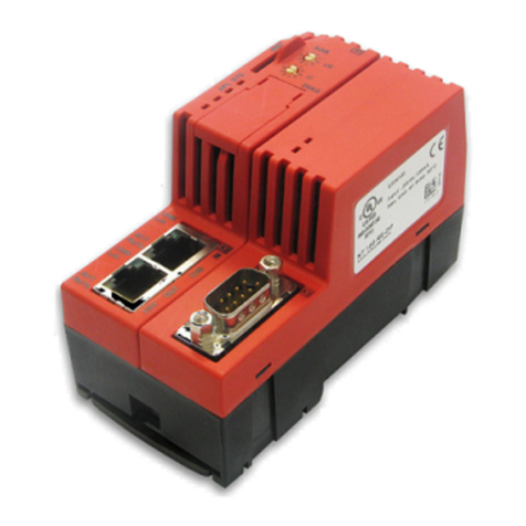
hilscher PKV 50 Series Application guide

Device Manual
PKV 50-XXX
Target System for Ethernet-/Fieldbus Applications
Edition: 3
Language: English (EN)
Hilscher Gesellschaft für Systemautomation mbH
Rheinstraße 15
D-65795 Hattersheim
Germany
Tel. +49 (6190) 99070
Fax. +49 (6190) 990750
Sales: +49 (6190) 99070
Hotline and Support: +49 (6190) 990799
Email Hotline and Support: hotline@hilscher.com
Web: www.hilscher.com

2 •
••
•Introduction PKV50
Copyright •Hilscher Gesellschaft für Systemautomation mbH •De:PKV50#3EN
List of Revisions
Index Date Version Chapter Revision
1 25.01.00 V1.000 all created
2 26.07.02 all revised
3 22.07.03 all Ported to Microsoft Word
PKV50-MBP
Although this appliance has been developed with great care and intensively
tested, Hilscher Gesellschaft für Systemautomation mbH cannot guarantee
the suitability of this appliance for any purpose not confirmed by us in
writing.
Guarantee claims shall be limited to the right to require rectification. Liability
for any damages which may have arisen from the use of this appliance or
its documentation shall be limited to cases of intent.
We reserve the right to modify our products and their specifications at any
time in as far as this contributes to technical progress. The version of the
manual supplied with the appliance applies.

PKV50 Table of Contents •
••
•3
Copyright •Hilscher Gesellschaft für Systemautomation mbH •De:PKV50#3EN
Table of Contents
1 INTRODUCTION .........................................................................................................4
1.1 Scope of Performance..............................................................................................4
2 STRUCTURE OF THE GATEWAY..............................................................................5
2.1 ISO/OSI Reference Model ........................................................................................5
3 GENERAL DEVICE DESCRIPTION............................................................................6
3.1 Hardware Description PKV50 ...................................................................................6
3.2 Configuration of the Gateway with the SyCon System Configurator .........................7
3.2.1 Loading Files into the Gateway ........................................................................... 8
3.2.2 Loading Files on to the Host PC .......................................................................... 9
3.2.3 Deleting Files ..................................................................................................... 10
3.2.4 Setting the IP Address ....................................................................................... 11
3.2.5 Starting Applications .......................................................................................... 11
3.3 Connecting the Supply Voltage (X2).......................................................................12
3.4 Interfaces ...............................................................................................................13
3.4.1 Ethernet-Interface (X4) ...................................................................................... 13
3.4.2 Fieldbus Interface (X6) ...................................................................................... 14
3.4.3 Diagnostic Interface (X3) ................................................................................... 16
3.5 Status Displays.......................................................................................................17
3.6 Mechanical Dimensions and Technical Data ..........................................................19
4 LISTS.........................................................................................................................20
4.1 List of Figures.........................................................................................................20
4.2 List of Tables..........................................................................................................21

4 •
••
•Introduction PKV50
Copyright •Hilscher Gesellschaft für Systemautomation mbH •De:PKV50#3EN
1 Introduction
1.1 Scope of Performance
In automation technology it is becoming obvious that Ethernet with the
TCP/IP protocol from the classical conductor field is moving continuously
forward into the fieldbus region. Although attempts are being made to lead
Ethernet up to the individual I/O modules, yet neither all the technical
aspects been satisfactorily solved nor can it be realized with a sufficient
effort.
This trend is further strengthened by the requirement for unbroken
communication from the office world up to the individual data point in the
industrial installation. Remote maintenance via the Internet is the buzzword
now.
This is where our fieldbus Gateway PKV 50 comes into its own. It connects
the Internet-/Ethernet world with the harsh industrial environment of
established fieldbus technology.
It consists of a Master interface connection, which, by means of one of the
standardized fieldbus systems, exchanges data between the connected I/O
devices and the internal process data memory. This data can be accessed
for reading and writing by means of TCP/IP telegrams.
The Microsoft Windows CE operating system is used on the Gateway.
Here, further tasks, such as SoftPLCs, are simply added in order to
incorporate extensions of the functions. The development system is
economical to build up and many engineers are familiar with the
development environment. All our interfaces are open so that the
experienced user can also bring his own applications into use on the
Gateway.
A further highlight is the integrated Web-Server. HTML pages can be
created on a corresponding editor and then loaded on to the Gateway.
Process data can be linked via Java Applets. All that is still needed to
access the data of the Gateway via the Internet is a Web Browser such as
for example, Microsoft Explorer or Netscape Navigator.
The configuration of the Gateways is carried out locally with our SyCon
System Configurator via the RS232C serial diagnostic interface or remotely
via TCP/IP.
The PKV 50 fieldbus Gateway is now offered for the most important
fieldbus systems.
Customer-specific solutions can be implemented by us or by the customer
himself.

Structure of the Gateway 5
Copyright •Hilscher Gesellschaft für Systemautomation mbH •De:PKV50#3EN
2 Structure of the Gateway
2.1 ISO/OSI Reference Model
Modern communication systems are structured in accordance with the
ISO/OSI reference model (ISO IS 7498). This is based on a 7-layer
structure. Here, every layer makes the services of the next higher layer
available but only uses the services of the next lower layer itself.
The Gateway fulfills this structure.
Figure 1: The Gateway in the ISO/OSI reference mode

6 •
••
•General Device Description PKV50
Copyright •Hilscher Gesellschaft für Systemautomation mbH •De:PKV50#3EN
3 General Device Description
3.1 Hardware Description PKV50
The Gateway consists of a basic circuit board with a power supply circuit
with DC/DC transformers in which all the required auxiliary voltages are
created. The fieldbus communication interface is based on the basic circuit
board, too.
The Elan SC520 processor board is inserted into the basic circuit board. It
contains a built-in timer, interrupt- and DMA-Controller and thus only
requires few external modules. The computing power is adequate for
processing even large quantities of data. Furthermore, the processor
ensures efficient software development in a high level language. The
firmware and the configuration data are stored in a FLASH-EPROM. This
can be programmed within the switching and retains its data even when the
operating voltage is switched off.
The proper function of the Gateway and its internal operating voltage is
monitored by a Watchdog circuit. In the case of error it triggers a Reset at
the processor.
The internal supply voltage is generated by means of a switched mode
regulator. Its input voltage is filtered via a current-transformed toroidal
choke and filter capacitors. A transient diode is available as spike and
polarity reversal protection. In the case of malfunction, a semiconductor
fuse switches the device down to a low residual current until the
malfunction is cleared. This means that the changing of an internal
sensitive fuse is dispensed with. Besides this, a charging capacitor is
available that blocks the voltage dips that occur in the switching of fuses.
The operational readiness and an error in the communication interface are
displayed by LEDs.

PKV50 General Device Description •
••
•7
Copyright •Hilscher Gesellschaft für Systemautomation mbH •De:PKV50#3EN
3.2 Configuration of the Gateway with the SyCon System
Configurator
The loading of new files on to the Gateway or the setting of the IP address
of the Gateway is carried out by means of the tools contained in SyCon.
In order to be able to use the configuration tools in SyCon, it is necessary
to lay down a configuration with a PKV 50 Gateway in SyCon. Now the
menu entry PKV50-XXX (XXX here stands for the selected fieldbus
system) appears in the Tools menu point. This makes it possible to choose
between a serial RS232 connection and a TCP/IP connection.
A crossed RS232 cable is necessary for operation at the serial interface
and this can be obtained from the Company Hilscher (CAB-SRV).
The configuration via TCP/IP can also be carried out via a point to point
connection with a crossed cable or, for example, via a Hub with commercial
Ethernet cables.
The Gateway is supplied with a default IP address (see information sheet).
Figure 2: Configuration dialog for the PKV 50-XXX Gateway via TCP/IP
The procedure for the serial configuration or the TCP/IP configuration is
basically the same. First an IP address must be entered into the field
provided for it or the serial interface with which the Gateway is connected
must be selected. Then the Connect switch must be activated. If a valid
connection to the Gateway has been established, then the menu entries
and the switches for configuration of the Gateway are released.
In order to ensure communication via TCP/IP, the TCP/IP protocol on the
PC must be configured in such a way that a connection with the default IP
address is possible.

8 •
••
•General Device Description PKV50
Copyright •Hilscher Gesellschaft für Systemautomation mbH •De:PKV50#3EN
3.2.1 Loading Files into the Gateway
This function enables to load files into the User FLASH of the Gateway and
to carry out applications after downloading or after the start of the operating
system.
Before a new application or a new and already available DLL can be
downloaded, any running older versions of the application or programs that
use DLLs must be ended. For this purpose, the corresponding running
processes can be displayed under the Configuration > View Running
Tasks menu. If an entry has been selected, then the Stop Process button
can be activated and the selected process is stopped.
In order to transfer a new file, select the File > Copy to PKV menu or
activate the Copy to PKV button. Select the file to be loaded in the dialog
that appears now.
Figure 3: Dialog for loading files on to the PKV 50 Gateway
The path and name can be entered directly into the Source (PC) text field
or select the path and file via the ... button. The Destination (PKV) field
cannot be edited at present. All the files to be copied are read into the
Windows directory of the Gateway. According to requirements, now mark
the buttons Save persistent, Execute after download and Execute after
PKV boot. Now activate the Download button and the software is
transferred to the Gateway.

PKV50 General Device Description •
••
•9
Copyright •Hilscher Gesellschaft für Systemautomation mbH •De:PKV50#3EN
3.2.2 Loading Files on to the Host PC
It is also possible to load files from the Gateway on to the Host-PC. For
this purpose select the Copy to PC entry in the File menu.
Figure 4: Dialog for loading files from the PKV 50 Gateway to the Host PC
Now the path of the file that is to be loaded can be entered directly into the
Source (PKV) field or the contents of the FLASH can be viewed via the ...
button and a file can be selected.
The target place and target name can be entered now in the Destination
(PC) field or selected via the ... button.
After activating the Upload button, the file is loaded onto the Host PC.

10 •
••
•General Device Description PKV50
Copyright •Hilscher Gesellschaft für Systemautomation mbH •De:PKV50#3EN
3.2.3 Deleting Files
In order to delete files, the menu point File > View Flash Dir can be
selected after building up the connection successfully. A list of files that are
permanently stored in the User FLASH memory is displayed now. Now
previously selected files can be deleted with the Delete button.

PKV50 General Device Description •
••
•11
Copyright •Hilscher Gesellschaft für Systemautomation mbH •De:PKV50#3EN
3.2.4 Setting the IP Address
Figure 5: Dialog for setting the IP Address
It is possible to allocate a new IP address to the Gateway with the
Configuration > Setting IP address menu. For this purpose, a connection
with the Gateway is necessary as already mentioned.
Note: The gateway has to be restarted to take over the IP Address.
Now enter the desired valid IP address into the corresponding field. Press
the Set button and the new address is allocated to the Gateway.
If the alteration of the IP was successful, it will be displayed. A request for
restarting the Gateway will appear.
Please note that the newly allocated IP address is only valid after a restart
of the Gateway.
3.2.5 Starting Applications
Applications that have already been entered on to the Gateway can also be
started manually. For this purpose the Configuration > Start Application
menu has to be selected. Now enter the name of the application into the
field provided for this purpose and press the OK button.

12 •
••
•General Device Description PKV50
Copyright •Hilscher Gesellschaft für Systemautomation mbH •De:PKV50#3EN
3.3 Connecting the Supply Voltage (X2)
The Gateway requires a supply voltage of 24 Volt. A three-phase rectified
supply or a simple rectified switching with charge capacitor is sufficient. The
supply voltage must be led to ground. It is connected by means of a plug-in
screwed clamp. Use is made of a 3-pin COMBICON plug from the
PHOENIX company (MSTB 2,5/3-ST-5,08).
Connection Symbol Signal
1 +24V +24V supply voltage
2 0V Reference potential
3 PE Equipment grounding conductor
Table 1: Connector pin assignment of the operating voltage connection X2

PKV50 General Device Description •
••
•13
Copyright •Hilscher Gesellschaft für Systemautomation mbH •De:PKV50#3EN
3.4 Interfaces
The PKV 50 Gateway possesses three independent interfaces.
First interface (X3). The first interface can be operated as a diagnosis /
configuration interface.
Second interface (X6). The second interface is designed for operation at
the fieldbus.
Third interface (X4). The third interface is used for connection to a
10/100BaseT network.
3.4.1 Ethernet-Interface (X4)
Connection Input/Output Signal designation
1 Output TXDE+
2 Output TXDE-
3 Input RXDE+
6 Input RXDE-
Table 2: Pin assignment of the Ethernet interface
The Ethernet interface is carried out by means of an 8 pin RJ45 socket for
a 10/100BaseT connection.

14 •
••
•General Device Description PKV50
Copyright •Hilscher Gesellschaft für Systemautomation mbH •De:PKV50#3EN
3.4.2 Fieldbus Interface (X6)
The following tables describe the pin assignment for the individual fieldbus
systems available on the PKV 50 Gateway.
3.4.2.1 PROFIBUS Interface for PKV 50-DPM
Connection
9 pin D-SUB
socket
Input/ Output Signal designation Signal
- - PE Earth ground
1- PE PNO recommend not to
use this signal
6 - VP Power supply
3 Input/
Output
RXD/TXD-A Data line
8 Input/
Output
RXD/TXD-B Data line inverse
4 Output CNTR-A Repeater control signal
5 - DGND Data reference potential
Table 3: Pin assignment of the PKV50-DPM at the plug X6
3.4.2.2 CAN-Bus Interface for PKV 50-COM, PKV 50-DNM
Connector
Connection
9 pin D-SUB
plug
Connection
5 pin
COMBICON
for DeviceNet
Input/
Output
Signal
designation
Signal
- - - PE Earth ground
95-+V
24V external power 1
3 - - DGND Data reference potential
7 4 Input/
Output
CANH Data line high
2 2 Input/
Output
CANL Data line low
6 1 - DGND Data reference potential
- 3 - shield shield of bus cable
Table 4: Pin assignment of the PKV 50-COM and PKV 50-DNM at the plug X6

PKV50 General Device Description •
••
•15
Copyright •Hilscher Gesellschaft für Systemautomation mbH •De:PKV50#3EN
3.4.2.3 Modbus Plus Interface for PKV 50-MBP
9 pol. DSub
female
connector
Symbol Signal Remark
1 Shield Is connected internal via 100 Ohm
with PE
2 DATA * Daten inverted
3 DATA Daten not inverted
RS485-signal level potential free
with transmitter
Table 5: Pin assignment of the PKV 50-MBP at the plug X6

16 •
••
•General Device Description PKV50
Copyright •Hilscher Gesellschaft für Systemautomation mbH •De:PKV50#3EN
3.4.3 Diagnostic Interface (X3)
The connection of a (Host) PC to the Gateway is also possible via the first
serial interface (X3). It corresponds to the RS232C standard according to
CCITT or DIN. However, only the required signals are available.
The control signals are served or evaluated as follows:
RTS is switched to high after the function readiness and not altered again.
CTS must be connected by means of a wire bridge with Pins 4 and 8 of the
D-Sub plug.
The transfer between Host PC and Gateway is at 9.600 Baud and the
following data format: 8 Data bits, 1 Stop bit and even parity. The 3964R
procedure is utilized as transfer protocol.
The connection of the PC is carried out with a three-wire cable which must
not be longer than 15 meters. The wiring of the cable is given below. For
better interference suppression, the cable shielding also on the side of the
Host PC should be grounded over the plug housing.
9 pin Dsub
f
e
m
a
l
e
co
nn
ec
t
o
r
Shield at connector
casing
9 pin Dsub
f
e
m
a
l
e
co
nn
ec
t
o
r
Table 6: Connecting cable between Gateway and Host PC

PKV50 General Device Description •
••
•17
Copyright •Hilscher Gesellschaft für Systemautomation mbH •De:PKV50#3EN
3.5 Status Displays
There are eight LEDs are the PKV 50 Gateway acting as status displays:
Display Color Condition Meaning
SYS,
CON,
ST1,
ST2
The condition of these LEDs
are application-dependent
and are described in the
corresponding manuals
RDY (*)(**) Yellow On
Cyclically flashing
Irregularly flashing
Off
Gateway ready
Bootstrap loader active
Hardware or system error
Hardware defect
RUN (**) Green On
Irregularly flashing (see
below).
Off
Fieldbus communication running
Parameterizing error (field bus)
No fieldbus communication
ERR / NET
/ CH_A
Fieldbus dependent Error on the
STA / MOD
/ CH_B
Fieldbus dependent
Table 7: Status Displays
Note (*): With a device defect, a cyclical flashing of the RDY-LED can also
be caused by the continuous accessing of the Watchdog monitoring.
Note: (**): These LEDs are not supported by the PKV50-MBP.
After switching on, the Gateway carries out a self-test. If this has been run
through successfully, then the yellow LED RDY is switched on. Otherwise
the LED begins to flash irregularly and the further processing of the
program is aborted.
If no fieldbus Firmware is loaded on the Gateway, then the Bootstraploader
shows this by a cyclical flashing of the RDY-LED in a 1-second rhythm.
During the loading of the Firmware the blink rhythm increases to
approximately 5 Hz.
If the LED remains off, then there is a defect of the Gateway.

18 •
••
•General Device Description PKV50
Copyright •Hilscher Gesellschaft für Systemautomation mbH •De:PKV50#3EN
If a fieldbus Protocol Task recognizes a parameterizing error, the Task is
displayed by the RUN-LED in accordance with the following figure.
If there is no error and communication could be started, then the RUN-LED
is switched on.
If the communication operation is blocked, the RUN-LED remains off.
Figure 6: Display of the tasks that have indicated a parameterizing error

PKV50 General Device Description •
••
•19
Copyright •Hilscher Gesellschaft für Systemautomation mbH •De:PKV50#3EN
3.6 Mechanical Dimensions and Technical Data
The Gateway is built into an aluminum profile housing. This permits direct
installation into the switching cupboard on a carrier rail (TS35 according to
DIN EN 50022).
The mechanical dimensions, the arrangement of the plugs and the
technical data of the PKV 50 are described in the Booklet of the PKV 50 on
the System Software CD.

20 •
••
•Lists PKV50
Copyright •Hilscher Gesellschaft für Systemautomation mbH •De:PKV50#3EN
4 Lists
4.1 List of Figures
Figure 1: The Gateway in the ISO/OSI reference mode 5
Figure 2: Configuration dialog for the PKV 50-XXX Gateway via TCP/IP 7
Figure 3: Dialog for loading files on to the PKV 50 Gateway 8
Figure 4: Dialog for loading files from the PKV 50 Gateway to the Host PC 9
Figure 5: Dialog for setting the IP Address 11
Figure 6: Display of the tasks that have indicated a parameterizing error 18
Other manuals for PKV 50 Series
1
Table of contents
Other hilscher Network Hardware manuals
