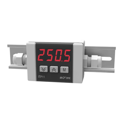
PROVU PD6100 Strain Gau
e, Load Cell, & mV Mete
Instruction Manual
3
Table of Contents
Table of Contents .................................................. 3
Table of Figures .................................................... 4
Introduction ........................................................... 4
Ordering Information ............................................ 5
Specifications ........................................................ 6
General ....................................................................... 6
Strain Gauge Input ...................................................... 7
Relays ......................................................................... 7
Isolated 4-20 mA Transmitter Output .......................... 8
Modbus
®
RTU Serial Communications ....................... 8
MeterView Pro ............................................................. 8
Compliance Information ....................................... 9
Safety .......................................................................... 9
Electromagnetic Compatibility ..................................... 9
Safety Information ............................................... 10
Installation ........................................................... 10
Unpacking ................................................................. 10
Panel Mounting Instructions ...................................... 10
Mounting Dimensions............................................ 11
Sensor Excitation Voltage Selection (EX+, EX-) ....... 11
Connections .............................................................. 12
Connectors Labeling ............................................. 12
Power Connections............................................... 12
Signal Connections ............................................... 13
Switch Configuration ............................................. 13
Shunt Calibration................................................... 15
Modbus RTU Serial Communications ................... 16
Relay Connections................................................ 16
Switching Inductive Loads..................................... 16
4-20 mA Output Connections................................ 17
Analog Output Power Supply................................ 17
F4 Digital Input Connections................................. 17
External Relays & Digital I/O Connections............ 18
Interlock Relay Feature......................................... 18
Setup and Programming .................................... 19
Front Panel Buttons and Status LED Indicators ........ 19
MeterView
®
Pro Software .......................................... 20
MeterView Pro Installation..................................... 20
Display Functions & Messages ................................. 21
Setting Numeric Values ............................................. 23
Main Menu ................................................................ 23
Setting Up the Meter (setup) .................................... 24
Setting the Input Signal (
Input
)............................ 25
Setting the Input Units (
units
).............................. 26
Setting the Input Units or Custom Tags (
units
) ... 27
Programming the Meter (
prog
) ............................. 28
Calibrating the Meter with Strain Gauge/Load Cell
(
Cal
)...................................................................... 28
Setting the Display Parameter & Intensity (
dsplay
)
.............................................................................. 30
Setting the Relay Operation (relay) ......................... 31
Setting the Relay Action........................................ 32
Programming Set and Reset Points...................... 33
Setting Fail-Safe Operation................................... 33
Programming Time Delay...................................... 33
Relay and Alarm Operation Diagrams ....................... 33
High Alarm Operation (Set > Reset) ......................33
Low Alarm Operation (Set < Reset).......................33
High Alarm with Fail-Safe Operation (Set > Reset)34
Low Alarm with Fail-Safe Operation (Set < Reset) 34
Pump Alternation Control Operation......................34
Relay Sampling Operation.....................................35
Time Delay Operation............................................35
Relay Operation Details ............................................. 36
Overview................................................................36
Relays Auto Initialization........................................36
Fail-Safe Operation................................................36
Front Panel LEDs...................................................36
Latching and Non-Latching Relay Operation.........37
Non-Latching Relay (
Auto
)....................................37
Non-Latching Relay (
A-man
)...............................37
Latching Relay (
LatcH
)..........................................37
Latching Relay (
Lt-Clr
)........................................37
Acknowledging Relays...........................................38
Pump Alternation Control Applications (
Altern
) ...38
Setting Up the Interlock Relay (Force On) Feature40
Scaling the 4-20 mA Analog Output (Aout) ............... 40
Setting Up the Password (pass) ................................ 41
Protecting or Locking the Meter.............................41
Making Changes to a Password Protected Meter..41
Disabling Password Protection ..............................41
Reset Menu (reset) .................................................. 42
Tare Menu (Tare) ...................................................... 42
Tare Functionality (
tare
).......................................42
Control Menu (Contrl) .............................................. 42
Advanced Features Menu .......................................... 43
Advanced Features Menu & Display Messages.....43
Noise Filter (
filter
)..............................................44
Noise Filter Bypass (
bypass
).................................44
Rounding Feature (
round
).....................................44
Modbus RTU Serial Communications (
serial
).....45
Select Menu (
SElect
)............................................45
Signal Input Conditioning (
Functn
)........................45
Auto-Zero (
Auto 0
)................................................46
Low Cutoff (
CutofF
) ..............................................46
Analog Output Programming (
AoutPr
) ..................46
Programmable Function Keys User Menu (
user
)..47
Internal Source Calibration (
ICAL
).........................48
Error Message (
error
)..........................................49
Meter Operation ................................................... 50
Front Panel Buttons Operation .................................. 50
Function Keys Operation ........................................... 50
Maximum/Minimum Readings .................................... 51
Troubleshooting .................................................. 52
Diagnostics Menu (diag) ........................................... 52
Determining Software Version ...............................52
Reset Meter to Factory Defaults ................................ 52
Factory Defaults & User Settings...........................53
Troubleshooting Tips (Including FAULT & ERROR
Messages) ................................................................... 54
EU Declaration of Conformity ............................ 55
www. .com information@itm.com1.800.561.8187


