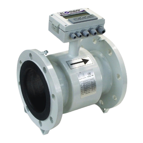
Flomag 3000 Owner's manual

FLOMAG s.r.o.
V Aleji 180/20a
CZ-620 00 Brno
Czech Republic
tel: +420 541212539
fax: +420 549240356
e-mail: info@flomag.com
www.flomag.com
Magnetic Flowmeter
LOMAG®3000
Installation and Operation

FLOMAG 3000 - Installation and Operation Manual
2

FLOMAG 3000 - Installation and Operation Manual
3
An magneticflowmeter isused
for volumeflowmeasurement of
electricallyconductiveliquids.
Measurement principleisbased
on Faradaylawon electromag-
neticinduction. Asensor con-
sistsofanon-magnetictube
withnon-conductivelining,
measuring electrodesandtwo
coilsgenerating electromag-
neticfield.Flowingliquidforms
aconductor. Magneticfieldin-
ducesvoltage Uinthisconduc-
tor that isproportionalto mag-
neticinduction B,distancebe-
tween electrodes dandflow
velocity v.
U =Bx d xv
Asmagneticinduction anddis-
tance between electrodesare
constant, induced voltage is
proportionaltovelocityofliquid
flowinthe tube. Volume flow
rate isproductofflowvelocity
and tubecross section.
Q=vx S Fig.1 - Principle ofmeasurement
Principle of measurement
Technical solution
The magneticflowmeter itself
consistsoftwobasicparts–a
flow sensor andaconverter.
The converter can beeither an
integralpart ofthe sensor
(compactversion) or separated,
connectedwiththesensorus-
ing a cable (remote version).
The sensor consistsofanon-
magnetictube with non-
conductivelining, measuring
electrodes,excitationcoilsand
cables.There are varioussen-
sor versionsavailableenabling
connectiontoadjacent tubes
with flanges(type P)and fittings
(gasfitting type Gorfood indus-
tryfittingtype V)or wafer which
are installedbetweenflanges
using clamps(type B). Non-
conductivelining can be made
oftechnicalrubber (types TG,
MG or NG) or Teflon (type T).
The converter isusedfor gener-
atingexcitation current incoils,
processing ofsignalfrommeas-
uring electrodes,displayingof
measured data andgenerating
output signals.Current inexci-
tation coilshasconstant value
250 mAor 125 mAand ispulse
generated with alternatingpo-
larityto avoidpermanent mag-
netizationofthesensor.Excita-
tionpulsefrequencycanbe
chosen fromsixvalues–25Hz,
12,5Hz,8,33 Hz,6,25Hz,
3,125Hzand1,56Hz.Excita-
tion currentof250 mAwithex-
citation frequency3,125 Hzis
suitablefor allstandard applica-
tions.Othersettingscanbe
used for specificapplications.
Excitation current andfre-
quencyarefactorysetbefore
sensor calibrationandtheirlater
modificationsare notallowed.
Voltageinducedinmeasuring
electrodesismeasured always
on theendofexcitation pulse
whenmagneticfieldissteady.
Eachexcitationpulseisfol-
lowedbyrefreshingperiod.Sig-
nalprocessing andparameter
settingare performed digitally
and theconverter contains no
settingcontrolsor othermoving
partswhatensuresitshighreli-
abilityand long-termstability.
T
t
I
+I
-I
m
m
1/8T 3/8T
1/8T
0
Fig. 2- Excitation pulse form

FLOMAG 3000 - Installation and Operation Manual
4
min 5 x DN min3 x DN
The flowmeter will givethebest
resultswhen flowofliquidis
steady.Therefore afewbasic
recommendationsshould be
observedfor itslocating ina
pipeline.There shouldbeno
transitionsbetweenthesensor
and the adjacent pipelinethat
couldbe asource ofturbulence.
Correctaxialalignment should
be observed duringinstallation.
Agasket shouldnotexceed
internaledgesoftubes.
Ifmore interfering elementsare
present near the sensor (e.g.
bends, fittings), required steady
length should be multiplied by
number ofthese interfering ele-
ments.
Reductionswith slopesup to 8°
can be includedinsteady
lengths.
xx
Minimumstraightsteady
lengthsofpipelinearerequired
on bothsidesofthe flow sen-
sor. Theirlengthshavetobe
proportionalto pipelineinternal
diameter.
Fig. 3- Overlaps
Fig.4 - Steadylengths
8°max
max45°
min 2 xDN
Fig.5 - Reduction
Ifwater inthepipelineis
pumped byawaterpump, the
sensor shouldbealwayslo-
cated behindthepumpto avoid
lowpressure thatcan damage
the sensor. Steadylength ofat
least25DNisrequiredbetween
the pump and the sensor.
Fig. 6- A water pump
For the samereason,never
locatestopvalvesbehindthe
sensor.
Fig. 7- Stop valves
The sensor can workboth in
horizontaland verticalpositions;
onlyaxisofmeasuring elec-
trodesinsidethe sensor must
alwaysremaininhorizontalpo-
sitionandtapping ofthe sensor
shouldbedirectedupwardsat
horizontalinstallations.
Fig. 8- Electrode axis
For verticalinstallations,liquid
should flowupwards.
Fig. 9- Verticalinstallation
Toensure correct measurement
and to avoidairlock,whole
sensor cross section shouldbe
flooded.Therefore never locate
the sensor inupper partsof the
pipelineor inverticalpositions
with liquid flowing downwards.
Fig.10 - Danger ofair lock
Ifpermanent flooding ofwhole
pipeline cross section cannot be
ensured, itispossibleto locate
the sensor inalowwatertrap
sothat itcan be alwayscom-
pletelyflooded. Freewaterdis-
charge shouldbe located2DN
higher than the sensor.
Fig.11 - Permanent flooding
Toavoidvibrationsthat could
damage the sensor, ensurethat
the adjacent pipelineisalways
supportedasnear tothesensor
aspossible.
Fig.12 - Danger ofvibrations
Where continuousflowoffluid
isrequiredandremovalof the
sensor isimpossible, abypass
shouldbeinstalled. Thesame
appliesfor locationswheresen-
sor removalwouldrequire
drainingoftoolongpart of the
pipeline.
Fig. 13 - Abypass
Installation instructions

FLOMAG 3000 - Installation and Operation Manual
5
Correct function ofthe magnetic
flowmeter requiresperfectelec-
tricalconnection betweenthe
sensor and theadjacent pipe-
line, grounding potentialand the
power supplyprotectivewire.
For the flanged sensor withthe
adjacent conducting pipeline,
flangesshouldbe electrically
connectedandthepipeline
grounded.
Ifthe adjacent pipelineis
non-conductive, groundingrings
shouldbe inserted initor
equivalent method shouldbe
Fig.16: Grounding rings
Fig.17. The wafer sensor
Fig.18: Cathodicprotection
Fig.15: Grounding offlanges
connection ofsensor clamping
flangeswithgrounding point of
the sensor.
Ifelectriccurrent flowsthrough
the pipeline,e.g.for pipeline
cathodicprotectionagainstcor-
rosion,thesensorshouldbe
electricallyisolatedfromthe
adjacent pipeline. The sensor
shouldbe bridged over using a
wire andgalvanicisolationof
the flowmeter power supply
shouldbeprovided so thatthe
flowmeter canbeisolatedfrom
allother devices.
Sensor grounding
Selection of suitable sensor lining and electrode material
Linings
Sensorshaveanon-conductive
liningfromvariousmaterials.
Choice ofmaterialdepends on
measured fluid characteristics.
· Technical rubber
Technicalrubber issuitablefor
lowaggressivefluidswithop-
erationaltemperaturesfrom0.1
°C to70°C.It fitsfor mostwa-
ter management andsewage
treatment applications.Itis
manufactured intwovariants
“TG” –with hard structureand
“MG” –withsoftstructure.Soft
structure isusedfor fluidswith
higher content ofabrasiveparti-
cles(e.g.sand). It isnotsuit-
able for drinking water.
· Resistant rubber
Type “NG” issuitablefor me-
diumaggressivefluidswithop-
erationaltemperaturesfrom0.1
°C to 90°C.It can be usedfor
measurement ofhot service
water, condensate etc., aswell
asfor drinking water. Iftem-
perature100 °C canbeex-
ceeded,Teflon (PTFE) lining is
recommended.
· Teflone or Hallar
Type “T” isthe mostuniversal
liningfor aggressivefluidswith
operationaltemperaturesfrom-
20 °Cto 150°C. It issuitable for
chemicalandfood industryap-
plications.
Electrodes
Choiceofmaterialofmeasuring
electrodesalsodependson
measured fluid characteristics.
· Stainless steel – “Ss”
Standardelectrodesaremade
ofstainless steelAISI 316Ti.
Theyare suitablefor allusual
water basedfluidsandfor lower
concentrationsofacidsand
caustics.
· Hastelloy C-22 – “Ha”
For somespecialapplications,
materialofhigher qualityshould
be used. HastelloyC-276 elec-
trodesare characterized byin-
creased resistanceagainstac-
idsand caustics and usuallyare
suitablefor mostofindustrial
applications.
· Titanium - „Ti“
Suitablefor someacids,
lyes,chlorine, urea and sew-
age.
· Platinum –“Pt”
For particularlyaggressiveflu-
idslikeconcentrated acidsand
caustics,chemicallyextremely
resistant materialshouldbe
chosen –platinum.However,
highcostofthismaterialis its
essentialdrawback.
*Note –Wecan recommend
suitableliningand electrode
materialsfor your particularap-
plication.
used to connectmeasuredfluid
electricalpotentialwithground.
For the wafer sensor, grounding
can be provided byelectrical

FLOMAG 3000 - Installation and Operation Manual
6
Converter iscapableto detect
flowratesaslowas0.1m/s.
Upper limitisdeterminedby
capabilityofliquidto maintain
continuousflowat higher veloci-
ties.Thisisusuallytrue forflow
ratesup to 12 m/s.
Measurement errorrapidly
increasesfor toolowflowrates,
ascan beseeninthediagram.
It showslimitsofmaximumrela-
tivemeasurement error asfunc-
tionofliquid flowrate.
Onthe other side, too high
flowratecausesdiscontinuityof
flowandresultsinchaotictur-
bulenceandvacuum traps.This
resultsininstablemeasurement
and toohigh driftofflow rate
values.
Idealoperationalrangeofthe
sensor isinrangefrom0.5 to 5
m/s.Thisrange ishighlighted in
the diagramfor correctsizese-
lection.
Flowrate rangesfor individual
sizesare chosento meet EN
14154standard and theyare
shownintable.Preferred
rangesare highlighted inbold.
For non-specifiedworkingme-
ters,other range can be also
specified on request.
Ifrange isnot specified ina
purchase order, the sensor will
be calibrated inpreferred range
in accordancewith the table
above.
Correct sensor size selection
10
1
0.1
Flow velocity [ m/s ]
Volumeflow rate
10 2 3 4 5 10 2 3 4 5 10 2 3 4 5 10 2 3 4 5 10 2 3 4 5 10
-2 -1 023
DN 10
DN 20
DN 25
DN 32
DN40
DN 50
DN 65
DN 80
DN100
DN 125
DN150
DN 15
DN200
DN250
DN 300
DN 350
DN400
DN 500
DN600
DN700
DN 800
DN900
DN 1000
DN 1200
2 3 4 5 10
10 2 3 4 5 10 2 3 4 5 10 2 3 4 5 10 2 3 4 5 10 2 3 4 5 10
-1 34
2 34 5
[ l/s ]
[ m/h]
32
Tab. Sensor rangesin m3/h according to their sizes
Fig. Limit ofmaximumrelativeerror ofmeasurement
Diagramfor correct sensor size selection.
DN
S10 A25 B25 C25 C50 D25 D50 D100
Range Q3/Q1
R10 R25 R25 R25 R50 R25 R50 R100
10 10.63 1 1.6 1.6 2.5 2.5 2.5
15 2.5 1.6 2.5 4 4 6.3 6.3 6.3
20 42.5 4 6.3 6.3 10 10 10
25 6.3 4 6.3 10 10 16 16 16
32 10 6.3 10 16 16 25 25 25
40 16 10 16 25 25 40 40 40
50 25 16 25 40 40 63 63 63
65 40 25 40 63 63 100 100 100
80 63 40 63 100 100 160 160 160
100 100 63 100 160 160 250 250 250
125 160 100 160 250 250 400 400 400
150 250 160 250 400 400 630 630 630
200 400 250 400 630 630 1000 1000 1000
250 630 400 630 1000 1000 1600 1600 1600
300 1000 630 1000 1600 1600 2500 2500 2500
350 1000 630 1000 1600 1600 2500 2500 2500
400 1600 1000 1600 2500 2500 4000 4000 4000
450 1600 1000 1600 2500 2500 4000 4000 4000
500 2500 1600 2500 4000 4000 6300 6300 6300
600 2500 4000 6300 6300 10000 10000 10000
700 2500 4000 6300 6300 10000 10000 10000
800 4000 6300 10000 10000
900 4000 6300 10000 10000
1000 6300 10000
1200 6300 10000
Range marking
0.25 0.5
0.5
1
1.5
2
2.5
3
0.75 1
±F
10 11 12
[ % ]
v[m/s ]
9
DN400..1200
DN10..25,250..350
DN32..200

FLOMAG 3000 - Installation and Operation Manual
7
Volba výstelkysníma eBlock diagram of the flowmeter
Mainadvantageofthemag-
neticflowmeter FLOMAG3000
isitssignificant variability.Flow-
meter converter inbasicversion
consistsonlyofpowersupply,
microcomputer and sensorin-
put module(module1). Display,
outputsand other optionalfea-
turesare availableasplug-in
modules.Thus,customer pays
onlyfor featuresthathereally
uses.Plug-inmodulescontain
memorieswhere allconfigura-
tiondata isstored. In thisway,
optionalfeaturescan beadded
or modified asrequiredanytime
duringtheservicelifeofthe
flowmeter.
There are 4free positions
available(module4, 5, 6and 7)
for binaryand analog output
modules.Theirsignalsareusu-
allyprocessed byconnected
technological devices.Alloutput
moduleshavegalvanicisola-
tion.At thesametime, up to 4
binaryoutput modulescanbe
fitted. Thesecan operate either
aspulseor frequencyoutputs
for flowrateindication. Alterna-
Power
supply
module 4 B1
Binaryoutput
module V1
Display
module 1 S1
Sensor input
module2F1
Electrodecleaning
module 5 B1
Binaryoutput
module 6 C1
RS 232 interface
module 7 A3
Analog. output
Microcontroller
module 3 M1
Data logger
Sensor
85-265 VAC
(24V,12V,AC/DC)
Fig. 19: Blockdiagramofthe flowmeter
tively,theycanservefor indica-
tionofflowmeter limitcondi-
tions.Galvanicisolation is en-
sured byanoptoelementor a
relay.Oneposition(module7)
isdedicatedfor the activeana-
logoutputmodule.Modules
withvariousaccuracyand
rangesare available. One posi-
tion (module6) isdesignedfor
the serialcommunicationmod-
ule. RS 232,RS485or M-
Businterfacecan be plugged
in.
Position(module2) isforthe
electrochemicalelectrodes
cleaningmodule.
A Module1
B Sensor connection
C Connected
D internally
E for compact version
1 module2 F2-F3
2
3 Not connected
4
5
6 module4
7 A4, B1-B5, E1
8 module5
9 A4, B1-B5, E1
10 module6
11 A4, B1-B5, C1, D1, D2, E1
12 module7
13 A1 - A5, B1-B5,E1
14
15 Not connected
16
17 L
18 NPowersupply
19 PE
Terminal connections
T0,5A
250V
ABCDE
1
2
3
4
5
6
7
8
9
1
0
1
1
1
2
1
3
1
4
1
5
1
6
P
E
L
N
B1B5C1A1
+
-
S1
V1
--
Magnetic flowmeterwww.flomag.com
LOMAG3000
Display
Sensor
connection
Relay ou
t
p
u
t
250VAC/
1
A
RS 232
0(4)..20m
A
Analog o
u
t
p
u
t
85 - 2
4
0
V
50 - 6
0
H
z
Power
T0,5A / 250V
Tab. Converter terminals Fig. 20 Converter –location ofterminals
The converter isintegratedina
ruggedaluminiumbox.After
openingthe boxyou will gain
access to terminals.Terminals
17, 18and19arefor power
supply.TerminalsA,B, C, D
and Eare used for thesensor.
For compactversion,the sen-
sor isconnected internallyand
terminalsremainfree. Termi-
nals1to16are usedfor con-
nectionofinputsand outputsof
optionalmodules(binaryout-
puts,current output,RS232,
RS485 etc.)

FLOMAG 3000 - Installation and Operation Manual
8
For the remote sensor, there
isaterminalboxinitstapping
(see figure 21). The sensor
shouldbe connectedtothe con-
verter usingadoubleshielded
cable. You canuseour special
sensor cable PAAR-LiYCY-CY
[1X(2X0,25LiYCY)+1X(2X0,75
LiYCY)+1X0,75]CY (lengthup
to 200m)or standard double
Maximumlength ofthe cable
between evaluation unitandthe
sensor issignificantlylimited by
conductivityofmeasured fluid,
asshownin Figure23.
Remote versionshouldbeused
when measured fluidistoohot
to avoidheattransfer to con-
verter.SeeFigure24for as-
sessment ofremote version
utilization.
Parallelrunning ofpowerand
0
25
50
100
200
0255075 100125150175200
Maximumlengthofcable [m]
Fluid conduc tivity
[ S/cm ]
m
shielded cable Lapp UNI-
TRONIC CyPiDy2x2x0.25 or
Alpha1243/2C (length up to 50
m).
Fig. 21: Sensor terminalbox Fig. 22: Remote sensor connection
signalwiresishighlyinappropri-
ate; especiallyincase ofthe
cablethat connectsthesensor
withtheremote converter.If the
instrument isused inenviron-
ment withstrong electromag-
neticinterference,cables
shouldberather asshortas
possible.
For connection ofelectronic
converter input and outputter-
minals,shielded cablesare suit-
able.
For connection ofmainsvolt-
age, astandard three-core ca-
ble,e.g. CYKY3x1,5(wire) or
VM03VQ-F 3x1 (wire strand) is
recommended. The instrument
hasnoswitchso itshouldbe
fused and switched using other
device.
Fig. 23: Maximumlengthofthe cableand conduc-
tivity
Fig. 24: Selection ofversion according to temperature
A B C D E
Yellow/Green
Yellow
Red
White
Brown
Green
AB
C
D
E
1
2
3
4
5
6
7
8
9
1
0
1
1
1
2
1
3
1
4
1
5
1
6
P
E
L
N
B1B1C1A3
+
-
S1
V1
Magneticflowmwter www.flomag.com
LOMAG3000
Display
Sensor
input
RS 232
4..20mA
Analog. output
85 - 265 V
48 - 63 Hz
T
0
,
5
A
/
2
5
0
V
AABBCCDDEE
PE
N
L
M
1
F
1
1
7
1
8
1
9
AABBCCDDEE
Sensor Sensor
ABCDEABCDE
Cable
PAAR-LiYCY-CY
[1X(2X0,25LiYCY)
+1X(2X0,75 LiYCY)
+1X0,75]CY
Cable
Lapp UNITRONIC
Cy PiDy 2x2x0.25
or
Alpha 1243/2C
-20
-10
0
10
20
30
40
50
60
-60-40-20 0204080
100
120
140
160
Fluid temperature[ °C]
A
m
b
i
e
n
t
t
e
m
p
e
r
a
t
u
r
e
[
°
C
]
TG,MG
NG T
Remote version
Heating
Remote or
compact
version

FLOMAG 3000 - Installation and Operation Manual
9
Displayed data
Fig. 25: Displayeddata
The instrument isequippedwith
ahigh qualitybacklittwo-line
alphanumerical displaywith
character height 9.6mm (2x16
characters)providinggood
readabilityevenfromlonger
distances.Backlight function
worksinenergysavingmode.
Backlighttimeislimited to 254
secondsafter lastpressingof
anykey.Ifbacklight isoff,
pressing ofanykeywillswitchit
on again. Backlight timecan be
set inmenu from20 secondsto
254 seconds.Setting to0
switchesbacklightpermanently
off;setting to255switchesit
permanentlyon.
Up to8basicreadingscanbe
read fromthe converter display.
You can alternatethemusing
1key.Additionalinformation
accessiblevia 2keyisavail-
able for some displayeddata.
Flow rate
-Flowrate value treatedby
floatingaveraging. Number of
averagingstepscanbe
changedinrange from1to 256.
Flowrateunitscanbechanged
asrequired.
Number ofdisplayed decimal
places canbesetinrangefrom
0 to 4.
Total volume (+)
-Totalvolumeofliquidflowed
indirectionofarrowonthe sen-
sor fromstart ofmeasurement.
Total volume (-)
-Totalvolumeofliquidflowed
inoppositedirection of arrowon
the sensor fromstart ofmeas-
urement.
Volume difference
-Differencebetweenpositive
and negativevolumesflowed
fromstart ofmeasurement.
Operation time
-Totaltimeofoperationfrom
initialswitching instrument on in
hoursand minutes.
Percent. flow rate
-Flowrate information indicated
byhorizontalbar (itswidthcor-
respondsto flowrate) andas
numericvalue inper centsof
chosen maximumvalue.
Last error
-Abbreviatedtextofthelast
error message.
Current flow rate
-Flowrate valueuntreatedby
floating averaging.
Temporary volume +
-User resettablevalue ofvol-
umeflowedindirectionofarrow
on the sensor.
Temporary volume -
-User resettablevalue ofvol-
umeflowed inoppositedirec-
tionofarrowonthesensor.
Temporary difference
-User resettablevalue ofdiffer-
encebetween volumesflowed
indirectionandinoppositedi-
rection ofarrowon the sensor.
Temporary time
-User resettablevalue ofvol-
umeflowedindirectionofarrow
on the sensor.
Valuesoftemporarycounters
can be reset byholding 3key
andsimultaneouspressing 4
key.Thiswillreset allcounters
at the sametime–both vol-
umesand time.
Batching
-Showsinformation aboutthe
running batch. Detailedinforma-
tionisgiven inchapter Batch-
ing.

FLOMAG 3000 - Installation and Operation Manual
10
Archiving
Electromagneticflowmeter
FLOMAG3000 automatically
savesinfixed timeintervals,
the value oftheflowedvolume.
There are threearchives.
Hour archivewhere itispossi-
bleto findtheflowedvolumes
aboutthe last192hours(8
days).
Dailyarchivewhere itispos-
sibleto findtheflowedvolumes
aboutthelast192 days(more
than half year).
Montharchivewhere itispos-
sibleto findtheflowedvolumes
about the last 12 months.
Upper lineshowsalwaystime
intervalofthe iteminthear-
chive. Second lineshowsthe
flowed volumeinthe fixedtime
intervalandthepowerofftime
inthe fixedtimeinterval(the
flowmeter waswithout power
supply).
Listing in archive
Pushing key 1,rollto item
Totalvolume+.Byrepeated
pushing ofkey 2youcanfind
graduallyFlowrate+,hourar-
chive, dayarchiveandmonth
archive.
Byrepeated pushing ofkey
3,inthehour archiveyoucan
see graduallythesaved sam-
plesfromthe previoushour,
totally192 hoursback.
Byrepeated pushing ofkey
3,inthedailyarchiveyoucan
see graduallythesaved sam-
plesfromthe previousday,to-
tally192daysback.
Byrepeated pushing ofkey
3,inthe month archive you
can see graduallythe saved
samplesfromthe previous
month, totally12monthsback.
Ifyou wanttogobackto the
lastsavedsample, please push
andholdkey3andtogether
with itpush key 4.
Fig. Hour archive
Fig. Dailyarchive
Fig. Month archive
Fig. Legend
Fig. Hour archive moving
Fig. Dailyarchive moving
Fig. Month archive moving
Ok- without power off
-#s- power off timein secunds
-#m- power off timein minutes
-#h- power off timein hours
-#d- power off timein days
Error messages
Fig. Error messages
In case of afault, an error
message with short de-
scription of the fault is
shownimmediatelyat the
LCD.
The error message begins
with character Efollowed
by error'snumber.If the
errorisconnectedwitha
defect of amodulethan it is
followed also bycharacter
Mand the number of the
module. Afterpushing but-
ton 1theflowmeter re-
turns to value displaymode
and at thesame timetheer-
ror messageissavedto last
errorregister. During the indi-
cation of the error message,
the flowmeter is measuring.
In caseof error E-7, E-8 and E
-13, theflowmeter indicates 0
if the mentionederrormes-
sage isnot forbidden inthe
menu.
Errormessages are listed
belowtogether with recom-
mendation howto repair.
E0: No error
E1: EEPROMChecksum
error
Checksum error saved in
the module-re-check data
inthemoduleandsave
again
E2: Stack overflow
For module„B“ inpulse
mode-thetimeconstants
are toolong, the flowrate is
higher than itispossibleto
send pulses,stack overflow
of un-sentpulses-change
pulse lengthandspace
length or volume for 1 pulse
E3: Frequencylimit ex-
ceeded
For module„B“ infre-
quency mode, itisrequired
higher output frequency than
the moduleisabletosend,
flow rateishigher thanit
wasassumed -set higher
flow rate valuefor 1kHz.
E4: Power fail

FLOMAG 3000 - Installation and Operation Manual
11
Appearsforshort after
power fail
E5: Old software
For properoperation of the
moduleisrequirednewer
firmware version than itis
installedinthe convertor –
upgrade firmware.
E6: Can't use this mode
For moduleBplaced in
position 6and 7isnotpossi-
bleto usefrequencemode
(itispossibleonlyinposition
4and5) –change theposi-
tionof the moduleor change
the modeto pulse.
E7: Sensor loop discon-
nected
No current to the coils–for
remoteversioncheck cables
and terminals
E8: Emptypipe
For modulesF2 andF3,
indicatesthat thecontrolling
electrodeisnot submerged
E9: Lowmedium conductiv-
ity
For modulesF1andF3 in
electrodescleaningmode,
no current inthe electrodes,
sensor isnotsubmerged,
electrodesarefurredorlow
mediumconductivity-clean
the sensor
E10: MBus conflict
ModuleD3–existtwosta-
tionsM-Buswithsamead-
dress – changethe settingof
moduleD3
E11:Current output
overrange
For moduleAitisrequired
higher outputcurrent than
20mA, flowrate ishigher
than itwasassumed–set
higher flow rate value for
Imax
E12: Seriallinefail -
communication error
Communication module
C1 or Dxsendsdata but
doesnotreceiveconfirma-
tionfor receiptofdata–
check cables,couldbe
caused alsobyexternalin-
terference, highcapacityof
the cablesor toolongca-
bles.
E13:Sensorsignalover-
range
Signalfrom the sensor is
overrange of theconvertor-
electrodesare notsub-
mergedor there isshort cir-
cuitofthecables–check
the sensor andthecables
User outputs – plug-in modules
T0,5A
250V
position 8
position 1
position 2
position 3
position 4
position 5
position 6
position 7
Flowmeter converterinbasic
configuration containsthe
power supplyand boards re-
quiredfor measurement func-
tions.Allother inputs,outputs
and displayunitscan beadded
asplug-inmodules.Customer
paysonlyfor featuresthat he
reallyuses.Atthesametime,
thisconceptallowsusingof
varioustypesofinputsand out-
putstailored to customer needs.
Following tableand figure
indicate positionsandfunctions
ofindividualmodules.
Fig.Modulepositions
Tab. Modulepositions
Po-
sitio
n
Modules Terminals
1S1 sensor input
module, always
pluggedin
A,B, C,
D, E
2F1-F3 module for
sensor fullpipe
checking and elec-
trode cleaning
1, 2,3,
4,
5,
3M1 extended memory
module ofmeasured
data
-
4A4,A7 passive cur-
rent output4 - 20mA
B1-B5 binaryoutputs
incl.frequencyup to
12 kHz
E1 binaryinput
6, 7
5A4, A7 passivecur-
rent output4 - 20mA
B1-B5 binaryoutputs
incl.frequencyup to
1,2 kHz
E1 binaryinput
8, 9
6A4, A7 passivec.o.
B1-B5 except for
frequencies,
C1, D1, D2, D3,G1,
H1 data communica-
tion
E1 binaryinput
10, 11
7A1-A3,A5, A6 active
current output
A4, A7 passivec.o.
B1-B5 except for
Frequencies
E1 binaryinput
12, 13
8V1 displayand key-
pad
10 pin
connec-
tor

FLOMAG 3000 - Installation and Operation Manual
12
Parameter setting
The magneticflowmeter con-
verter can be configured intwo
ways,asrequired: either using
aPCconnected viaserialinter-
face, or using keys.
Press 4toswitch thedisplay
to programming mode. Pro-
gramming mode ispassword
protectedagainstunauthorized
access.Correctpassword(4-
digitnumber) mustbe entered
to obtainaccess to mainmenu.
Password ofanewinstrument
isalwayssetto 0000.
Fig. Enter password
Thisisalso initialvalue dis-
playedasdefault.Simplycon-
firmit to enter inmenu.
Password can be changed as
requiredbefore youleavethe
programming mode.
Warning!You canswitchthe
instrument to datadisplaymode
anytimebypressing 1and
checkcurrent parameter set-
tings.However, the instrument
isnot passwordprotected
againstunauthorizedaccess
untilyouenter EXITcommand.
Programming runsinback-
groundand with onlyafewex-
ceptionshasno influenceto
measurement.
Fig. Cursor movement
2keymovescursor tothe
right.When the utmostright
positionisreached,thecursor
returnsto the left.
Fig. Character changing
systemreturnsto thefirstavail-
able character.
Character set isalwaysse-
lectedwithregardtopossibility
ofcharacter occurrencein text:
[0..9]for integers,[0..9,- ,.] for
decimalsand completealpha-
bet for textvariables(including
Czech characters).
Confirmyour selectionby 4
keytofinishediting.
Astatusmessage willbe dis-
played. Ifyour password is not
accepted,programreturnsto
editingmode. Ifcorrectpass-
word wasentered,youwillget
to main menu.
Use 3to moveinmenu. This
keymovesthelower lineitemto
upper line. Inallmenus,the
upper line with blinkingfirst
character isalwaysthe active
line.
Press 4to enter insubmenu
or toedititem.Pressing2
insubmenu bringsyou always
backto previousmenu
(“Escape” function). Ifyouare in
mainmenu, pressing ofthis key
willoffer exitfromprogramming
mode.
Menu legend
Somemenu itemscan be
used onlyfor viewinganddo
not allowchangeofvalues.
Fig. Movement in menu
Fig. Statusmessage
+ Noisefilter
+ Dynamicfilter
»Enterpassword
○125 mA
●250 mA
¤Production date
3keychangescharacter at
cursor position. When the last
availablecharacter isreached,
Fig. Read only
Fig. Enter value
Press 4 to return toprevious
menu.
Other menu itemscan be
used toenter value directly.
When you enter thevalueand
press 4,astatusmessagewill
be displayed.
Ifthe valueenteredisac-
cepted, press anykeytoreturn
to previousmenu ortoeditnext
item.
Ifthe valueenteredisoutof
range,anerror message willbe
displayed;press anykeytoedit
the value.
In somecases,one oflisted
valueshasto be selected.
Fig. Selection ofonevalue
Use 3toselectrequired item.
When the required value isin
the upper line,press 4tocon-
firmyour selection. Astatus
message willbedisplayedto
confirmthat your selectionhas
beenaccepted. Press anykey
to return topreviousmenu or to
editnextitem.
In somecases,more oflisted
valuescanbe selected.
Fig. Selection ofmore items
There isasign “+”(indicating
that theitemisselected) or “-
“(indicatingthat theitemisnot
selected) before each ofitems.
Fig. Selection ofmore items
Press 2to changeselection
for the itemdisplayedinthe
upper line.Press 4tofinish
your selection. Astatusmes-
sage willbe displayedtocon-
firmthat your selection has
beenaccepted. Press anykey
to returnto previousmenu.

FLOMAG 3000 - Installation and Operation Manual
13
Flowmeter menu
»Enterpassword
↓
0.Production data →Production date →¤Production date
Serialnumber →¤Serialnumber
Software →¤Software
Meter'stype →¤Meter'stype
Modulesused →¤Embeded modules
Datesetting →»Date
Timesetting →»Time
Permit upgrade →»Upgrade PIN
Deletehistory →»DeletePIN
Reset volumes →»Reset PIN
1.Sensor →Sensorconstants →Constatnt 1 →»Sensorconstant1
Constant 2 →»Sensorconstant2
Excitation freq. →○2.775 Hz
●3.125 Hz
○5.55Hz
○6.66Hz
○12.5Hz
○25Hz
Excitation curr. →○125mA
●250mA
Supressed flow →»Donot meas. Q<
Samples →»Samples
Filters →√Noisefilter
√Dynamicfilter
Zerosetting →»AutozeroPIN
2.Module2 →Specificsettingsforindividualmodules
…
7.Module7 →Specificsettingsforindividualmodules
8.Display →Language →●[CZ] Česky
○[D]Deutsch
○[GB] English
○[PL] Polski
○[I] Italiano
○[NL] Nederlands
○[S]Svenska
○[E]Espanol
○[F]Francais
100 percent →»100percent
Flowrateunits →●l/s
…
○m3/h
…
○User's →»Flowratemultipl
»Unit'sname
Decimalplaces →»Decimalplaces
Backlight →»Backlight time
Displayselect →√Flowrate
√Totalvolume+
√Totalvolume+
√Totaldifference
√Operation time
√Percent flowrate
√Last error
√Realtime
Errormessages →√E1
√…
√E13
9.Exit →Exit menu
Exitmenu
Newpassword →»Access password

FLOMAG 3000 - Installation and Operation Manual
14
0. Production data
Thissubmenu relatestothe
flowmeter converter.
·Production date – ofcon-
verter
·Serial number –ofcon-
verter
·Software –current soft-
ware version
·Type of meter – type num-
ber offlowmeter converter
·Modules used –typesof
currentlyusedmodules
(Abovelisteditemsare only for
information and user cannot
changethem)
·Date setting –setting of
current date
·Time setting –setting of
current time
·Upgrade enabled – anew
firmware versioncanbe
uploaded after entering PIN
·Deletehistory –archives
willbedeletedafter entering
PIN
·Resetvolumes – Alltotal-
izerswill be reset after en-
teringPIN
1. Sensor
Thissubmenu relatestothe
sensor.
·Sensorconstants –sen-
sor calibration constants
·Excitation frequency –of
sensor coils
·Excitation current –of
sensor coils
·Suppressedflowrate –
whenflowrateislowerthan
thisvalue,itisconsidered
for zero. Thissetting isused
to suppress creeping flows.
·Number of samples – for
floatingaveragingthat filters
measured flowrate value.
Higher number ofsamples
providesmore stableflow
rate value, however itin-
creasestimeconstant and
causesdelayedreaction to
flowrate changes.
·Filters
¨Noise filter partiallyre-
ducesjumpchangesbut
mainlyremoveslower peri-
odicalinterference. Tran-
sient edgesare roundedas
can be seeninfigure ofre-
sponsetounitjump. The
filter isappliedalreadyon
input andthusinfluences
immediate flowrate value
and cumulated volumecal-
culatedfromit. The noise
filter introducesonlynegligi-
bledelay(about0.3sec)
and can beused almostat
allcircumstances.
¨Dynamic filter reduces
rapidjumpchangesofflow
rate. It protectsveryeffec-
tivelyagainsthigh short
peakscaused byinterfer-
ence. Unlikeaveraging, dy-
namicfilter cutsinput signal
and interferenceisnot in-
cludedincumulatedvol-
ume. It can however cause
delayofflowratejump
change indication. Thisfact
shouldbe consideredifthe
flowmeter isused for dosing
applications.Responseto
unitjumpcan beseenin
figure.
8. Display
Thissubmenu relatestodata
shown on the display.
·Language –languageof
displayeddata. You can
select from9 languages.
·100 percent – 100 %flow
rate for bar diagram.It is
Fig. Dynamicfilter
Fig. Noise filter
used onlyforpercentage
bar diagramdisplay;itisnot
meant asrange ofthe me-
ter.
·Flowrate units – You can
selectfrom12 presetunits
or add your ownuser de-
fined unit.Insuchcaseyou
havetoenter multipleof
flowrate inl/sanda unit
name.
·Decimalplaces –Number
ofdecimalplacesofdis-
playedflowrate. Youcan
enter 0-4 decimalplaces.If
5placesare entered, num-
ber ofdecimalplaceswill be
dynamicallychanged to4
validdecimalplaces.
·Time of backlight –Time
ofdisplaybacklight insec-
onds.When you press any
key,backlight ofdisplay
goeson. When timeperiod
set insecondsexpiressince
you pressedthelastkey,
the backlight goesoff.You
can settimeperiodfrom1
to 254 seconds. Ifyou set 0,
backlight willneverbeon. If
you set 255,thedisplaywill
be permanentlybacklit.
·Displayed values – De-
fineswhatitemswill bedis-
played. You can selectany
ofavailableitems.These
willbealternatelydisplayed
on theflowmeter display.
Press 1toalternatedis-
played values.
·Errormessages –Enable
or disabledisplaying ofindi-
vidualerror messages.
9. Exit
·Exit menu –When you
finishediting, youhaveto
exitmenu becauseonlyaf-
ter that settingsare perma-
nentlystored inmodule
memories.Ifyouwill not exit
the menu and power failure
occurs,previouslyentered
settingswillbe loaded. Also
access to menu ispassword
protectedonlywhen you
exit menu.
·Newpassword –Youcan
changetheaccess pass-
word before youfinishyour
editing.
Time
N
t
N
Samplingmoments
Current flow rate
Flow rate
Average flow rate
Fig. Averaging

FLOMAG 3000 - Installation and Operation Manual
15
ModulesA–analogcurrent
output –are usedfor flowdata
transmission. There are 4differ-
ent typesavailablewithvarious
ranges, accuracyand functions.
OutputsofA1 toA3, A5and
A6 modulesareactive(forced
current) andare galvanically
isolated fromother flowmeter
parts. Outputscan beloaded up
to 1000 Ω. Theycan be plugged
onlyin position 7.
A4 andA7 moduleshavepas-
sivecurrentoutput(ithastobe
poweredexternally)andare
alsogalvanicallyisolated.
UnlikeA1-A3,A5, A6 modules,
itcanbepluggedinpositions4,
5 and 6.
0..+Qoutput
0..-Qoutput
IQI output
-Q..+Qoutput
Fixed current 0..20
Depending onflowrate(see
diagrams), output canworkin5
modes:
The firstfour modesgenerate
output current dependenton
flow rate,the fifth mode enables
directentering ofcurrent.Fol-
lowing4rangescanbese-
lected for allmodes(except for
the fixed current mode):
A3, A4, A6and A7 modules can
workonlywithrange 4..20 mA.
0..20mA output
4..20mA output
0..10mA output
0..5mA output
Range 4..20mA0..10mA0..5mA
Flowrate /current -Qmax 0 Qmax -Qmax 0 Qmax -Qmax 0 Qmax -Qmax 0 Qmax
0..+Qoutput 0 0 20 4 4 20 0 0 10 0 0 5
0..-Q output 20 0 0 20 4 4 10 0 0 5 0 0
0..IQI output 20 0 20 20 4 20 10 0 10 5 0 5
-Q.+Qoutput 0 10 20 4 12 20 0 5 10 0 2,5 5
0..20mA
A1
Range 0(4)..20 mA
Resolution 12 bit
Accuracy±0.2%, ±0.2mA
Active - replaced byA5
A2
Range 0(4)..20 mA
Resolution 16 bit
Accuracy±0.1%, ±0.1mA
Active - replaced byA5
A3
Range 4..20 mA
Resolution 16 bit
Accuracy±0.1%, ±0.1mA
Active - replaced byA6
A4
Range 4..20 mA
Resolution 16 bit
Accuracy±0.1%, ±0.1mA
Passive - replaced byA7
A5
Range 0(4)..20 mA
Resolution 16 bit
Accuracy±0.1%, ±0.1mA
Active
A6
Range 4..20 mA res. 16 bit
Accuracy±0.1%, ±0.1mA
Active - compatiblewith
module H1 ( HART)
A7
Range 4..20 mA res. 16 bit
Accuracy±0.1%, ±0.1mA
Passive - compatiblewith
module H1 ( HART)
Current output modules A1 – A4
Fig. 0..+Qoutput
Fig. 0..+Qoutput
Fig. IQIoutput
Fig. -Q..+Qoutput
Fig. Menu structure ofA modules
7.Current output →●0..+Qoutput ○0..20mAoutput»Imaxflowrate
○0..-Qoutput ●4..20mAoutput
○0..|Q|output ○0..10mAoutput
○-Q..+Q output ○0..5 mAoutput
○Fixedcurrent»Fixed current[mA]
1213
A5
0..20 mA
Curr ent output
+-
A
+
-
1011
A7
4..20 mA
Curr ent output
+-
A
+
+
-
ModulesA6and A7 enables
with moduleH1(Bell202 mo-
dem)to communicate through
current loop with aprotocol
compatablewithHART(only
UniversalCommands)

FLOMAG 3000 - Installation and Operation Manual
16
B1
Passive (max4 kHz)
Max. voltage350 Vp-p
Max. perm. current 120 mA
Max. pulse current 300 mA
Resistance27 Ω
B2
Passive (max12 kHz)
Max. voltage60 Vp-p
Max. perm. current 300 mA
Max. pulse current 500 mA
Resistance5 Ω
B3
Active
Voltage 5 V
Max. current 10 mA
Max. frequency12 kHz
B4
Active
Voltage 24 V
Max. current 40 mA
Max. frequency12 kHz
B5
Relaycontacts
Max. voltage250 VAC
Max. current 1 A
Binaryoutput modules B1 - B5
Flowmeter converter can con-
trolup to 4multifunctionalbi-
naryoutputsinpositions4–7.
Following tableindicatesdiffer-
encesbetween individualmod-
ules:
Outputscanworkaspulse,
frequencyor statusoutputs.
Individualfunctionsareex-
plainedindetailinfollowing
section.
Binary modulefunc-
tions
·Normally closed/open
Thesemodesare used for ser-
vicepurposes.
·Pulseoutputs (not)
In thismode, apulseisgener-
ated immediatelyafter preset
volumehasflowed.Pulse gen-
erationisdeterminedbythree
factors:pulselength “t
u
”, mini-
Tab. Binaryoutput modules
maldelaybetween twopulses
“tD” and volume per pulse “V”.
Flowratevaluesare timeinte-
grated.Immediatelyafter preset
volumeper pulse hasflowed,
the pulseoflengtht
u
isgener-
ated. After the pulse, thereisa
delayoflengthat leasttD.If the
delayexpiresand thepreset
volumehasnotflowed again,
the outputremainsinactive;
otherwise, anotherpulse and
delayaregeneratedimmedi-
ately.Ifthe preset volumeflows
throughsooner than theprevi-
ouspulse isfinished,theunsent
pulse willbestoredinabuffer
with maximumcapacityof255
pulses.Ifbuffer overflow oc-
curs,an error message willbe
generated.It followsfromabove
mentionedthatparametersof
pulse outputshouldbeset such
thatexpected pulsefrequency
cannot exceedlimitfrequency
determined bypulse length and
delay.
It applies:Maximum pulse
frequency [s-1] =1 / (tu+tD)
Volume per pulse can beset in
range from 1to 109mlwith1ml
step, i.e. from1mlto 1000m3
.
Delayandpulselengthscanbe
set inrangeform 10 msto 2550
ms with 10msstep. Itfollows
fromabovementionedthatthe
maximumpulsefrequencyis50
s-1.
Pulsescanbegeneratedin
three modesdependingon flow
rate, andpulse polaritycanbe
set (output isclosedduring
pulseor open innot modes).
Fig. Pulse generation
Fig. IQIpulses
Fig. Q+pulses
Fig. Q- pulses
·Frequency outputs
In thismodeofoperation,fre-
quencyisgenerated onoutput
modules.Pulsetodelayratiois
always1:1. Warning!Onlytwo
frequencygeneratorsinposi-
tions4and 5are availablefor
the converter. Thisfunction is
blocked inpositions6and7.
Maximumfrequencyinposition
4is12 kHzandinposition 5
only1.2 kHz.Iftheselimitfre-
quenciesareexceeded,output
frequencywillbe limited andan
error message will be gener-
ated.
Frequencyoutputscan work in
three modesoffrequencyde-
pendenceon flowrate.
Setting isdone byselectingof
flowrate corresponding to 1
kHzoutputfrequency.
Fig. Q+frequency
Fig. Q- frequency
Fig. IQI frequency

FLOMAG 3000 - Installation and Operation Manual
17
Fixed frequencymode isused
for servicepurposes.Required
frequencyisset directlyinHzin
range 1-120000 Hzinposition 4
and 1-1200 Hzin position 5.
· Negative/non-negative
flowrate
Thismode isusedfor flowdi-
rection differentiation. Output is
closed/openfor negative flow
rate.
· Failureoccurred/not oc-
curred
Iffailure withmode set to active
(see error messages)occurs,
the output closes/opensfor at
least5seconds.Iffailureper-
sists,outputisclosed/openfor
whole period offailureduration.
· Limit flowrate exceeded/
undergone (not)
Ifflowrateishigher/lower than
limitvalue set, the outputcloses
(opens). When flow ratereturns
to limits,the output opens
(closes)againtaking inaccount
preset hysteresis.Thisfunction
Fig.Q>Qlimit
Fig.Q<Qlimit
Fig.IQI >Qlimit
Fig.IQI <Qlimit
Fig. Menu structure ofB modules
Fig. Terminalconnection
67
B1
Binary out pu t
Opt oMOS 35 0V
89
B2
Binar y out put
ac tiv e 5 V/ 1 00 mA
+
-
89
B5
Binar y out put
Re lay
4.Binary output ─►●Permanentlyopen
○Perm. Closed
○IQIpulses»Pulselength[10ms]
○IQInot pulses»Pauselength[10ms]
○Q+pulses»Vol./ pulse[ml]
○Q+not pulses
○Q-pulses
○Q-not pulses
○Q+frequency»Flowrateat 1kHz
○Q-frequency
○IQIfrequency
○Fixedfrequency»Fixed frequency [ Hz]
○Negativeflow
○Non-neg. flow
○'Erroroccured √E1
○'Noerroroccured √…
√E13
○Q>Qlim.»Flowlimit
○Q>Qlim. not»Hysteresis
○Q<Qlim.
○Q<Qlim. not
○IQI>Qlim.
○IQI>Qlim. not
○IQI<Qlim.
○IQI<Qlim. not
○Cleaning
○Not cleanig
○BatchOpened»VolumeAdvance[ml]
○BatchOpened not»TimeAdvance[ms]
○BatchStop puls»Pulselength[10ms]
○BatchStop /puls»VolumeAdvance[ml]
»TimeAdvance[ms]
worksinfour modesofdepend-
enceonflowratewithoutput
polaritydifferentiation.
· Electrodecleaning/no
cleaning
The output isclosed/opendur-
ing cleaning.
· Batch Opened
· Batch /Opened
Output isswitched on /
switched off during the batch
running. It ispossibleto setthe
advanceofthe output before
batchending. Advancecouldbe
set bytimeor volume. Detailed
information isgiveninchapter
Batching.
· Batch Stop pulse
· Batch Stop /pulse
Output generatespulse for
ending ofthe batch. It ispossi-
bleto set pulselength(10ms -
2,5s)andpulse advancebefore
batchending. Advancecouldbe
set bytimeor volume. Detailed
information isgiveninchapter
Batching.

FLOMAG 3000 - Installation and Operation Manual
18
C1, D1, D2 and D3 modules
ModulesC1,D1, D2 and D3
are usedfor data communica-
tion.All thesemodulesaregal-
vanicallyisolatedfromflow-
meter circuits.Theycanbein-
stalled onlyinposition6and
theirsignalsare output to termi-
nals10 and 11. Interface
RS232istheonlyexception, as
it needs3 wires.
C1 –RS232 inter-
face
It isusedprimarilyfor
servicepurposes,be-
causemaximumcable
length fromthe converter
to acomputer is15me-
tersandonlyonecon-
vertercan beconnected
to a singlelink.
Connectionto thecom-
puter equipped with RS232in-
terfaceisdone usinganin-
cludedcable.Threadone end
ofthe cablethroughacable
bushing andconnectitto 3-pin
connector behind terminals 10-
11. The other end ofthe cable
isequipped withCANON9M
connector.Thisensuresleading
ofRS232interfacesignals out
ofconverter boxwhileprotec-
tion levelIP66 ismaintained.
The interfaceisconnectedto
the computer using acrosslink
cableLaplink9F-9F.
D1 –RS485 interface
It isusedfor permanent con-
nectionofmultipleconvertersto
the computer. Itenablescon-
C1 RS232
D1 RS485 (MODBUS)
D2 0/20mA data current loop
D3 M-BUS
G1 GSM modem
H1 HARTmodem (with A6,7)
12345
6789
CANON 9F
12345
6789
CANON9M
1011
C1
RS232
Fig.RS232 cable connection
nectingofup to31stationsina
communicationnetworkusing a
twisted pairlinkcablewith total
length of1200 meters.Number
ofstationsandlength ofcables
can be increasedbyusingre-
peaters.Stationsare connected
to the linkinparallel.The most
distantendsoflinehavetobe
equipped with terminatingresis-
tors120 Ω.
When setting stations,be
sure to set the samebaudrate
for all ofthemand toset a
uniqueaddress for eachof
them.MASTER address isal-
wayssetto“0” andaddresses
ofindividualstationscan beset
in range 1-254.
D2 –Data current loop
interface 0/20 mA
It isusedfor permanent con-
nectionofmultipleconvertersto
the computer. Itenablescon-
nectingofmultiplestations on
longdistances.Datatransfer
viacurrent coding 0/20 mAis
highlyresistant againstinterfer-
enceandissuitablefor indus-
Fig. RS485 networkconnection
Fig.Data currentloop 0/20mA
networkconnection
trialenvironment. Individualsta-
tionsare connectedinseries.
Disadvantageofthisconfigura-
tion isthat ifone station fails,
then wholenetworkbreaks
down.
D3 –M-BUS interface
Standard M-Bus(Meter-Bus)
isdesigned for applicationsof
data acquisitionfromvarious
mediaconsumption meters.It
enablesconnectingofmany
devices(hundredsofthem)on
distance ofseveralkilometers.
Fig. M-Busnetworkconnection
Fig. Communication module menu
M-BUS
DEVICE 1 DEVICE 2
DEVICE
3
M-BUS M-BUS
M-BUS
MASTER
10
11
10
11
10
11
6.RS232 ─► Baudrate ─►○300Bd
○600Bd
○1200Bd
○2400Bd
○4800Bd
●9600Bd
○19200 Bd
○38400 Bd
○57600 Bd
○76800 Bd
○115200Bd
Adress ─► »Ownadress
Protocol ─►●FLOMAG
○M-BUS
○MODBUS-RTU
○MODBUS-ASCII
○HART
Parity ─►●No parity
○Oddparity
○Evenparity
Wordorder ─►●Lowwordfirst
○Highwordfirst

FLOMAG 3000 - Installation and Operation Manual
19
Modul E1
ModuleE1isgalvanically
separated active binaryinput for
nonvolatilecontactsor open
collector. Input hasSWtran-
sient immunity. It isnecessary
min pulse length of60msfor
switching .
Functions of the binary
input
· Switch Off
· Batch Start
Startsthe batch (see section
Batching).
· Batch Hold
Stopsand holdsthe batch.
Counted batch can becontin-
ued after restarting it (see sec-
tionBatching).
· Batch Stop
Asynchronouslyfinishesthe
batch and setsagain the preset
batchvolume (see section
Batching).
· Reset Volumes
Enablesreset ofthe chosen
totalizersandworking time.
· Cleaning Start
Startselectrochemicalelec-
trodescleaning in modulesF1
or F3 (requiresplug-in modules
FigMenuofmodule E1Fig. Terminalconnection
2. Electrodecleaning ─► ●OFF
○Onlyonce
○DuringPowerON
○Periodiccally ─► »Cleaneveryx[h]
»Timeofstart[h:m]
F1, F2 and F3 modules
F1 –F3 modulesare usedfor
full pipecheckandfor electro-
chemicalcleaningofelectrodes.
F1-Electrochemical
electrodecleaning mod-
ule
Duringoperationoftheflow-
meter, anon-conductivelayer
can be formed on sensor elec-
trodes.Thislayerincreases
contactresistancebetween
electrodesandmeasured fluid
and resultsinlower measure-
ment accuracy.
F1 moduleenablesmeasur-
ing electrodecleaning without
need ofsensor deinstallation.
The method isbasedonelec-
trochemicaleffect. Alternating
voltageisconnectedtoelec-
trodesandthe depositedlayer
dissolvesinliquid. Thiscleaning
shouldbe performed periodi-
F1 Electrochemicalelec-
trode cleaning module
F2 Emptypipe detection
module
F3 Modulewith combined
functionsF1+F2
cally.
The cleaning cycletakes1
minute. During cleaning,noreal
measurement isperformed.
Flowratemeasured before start
ofcleaningissimulated. Clean-
ingcycleduration canbe indi-
cated usingbinaryoutputs.
Running cleaningprocessis
indicatedondisplaybymoving
full character on upper line.
The instrument offersseveral
possibilitiesofcleaning cycle
start:
IfONCE isselected, asingle
cleaningcycleisimmediately
performed and then theinstru-
ment returnsto Off mode.
IfAFTER SWITCH-ONisse-
lected, thecleaningcyclewillbe
alwaysstartedifpower supply
isswitchedon. Option PERI-
ODIC startscleaninginregular
intervalsthatcan beset byuser
inrange from1to 255 hours.
Timer startscounting aftertime
valueisentered.Startingtime
ofcleaning can be set to match
to realtime. It makessense
onlyifcleaningperiod isset in
multiplesof24 hours.Then
cleaningwillbeperformedal-
waysinpreset time. F1 module
hasnowiresconnectedtothe
terminalblock.
F2 -Full pipe check
module
Correctmeasurement offlow
rate bythemagneticflowmeter
isconditionedbyfullflooding of
the wholesensor cross section
bymeasured liquid.Ifflooding
isonlypartial,the magnetic
flowmeter will indicate flow rate
higher thanreal.However, if
bothelectrodesare notim-
mersed inliquid, interferingvolt-
age can begeneratedon elec-
OFF
Onlyonce
During power ON
Periodically
Fig. F1 module menu
4. Binaryinput ─►●Off
○BatchStart
○BatchHold
○BatchStop
○Reset Counters ─► √Totalvolume +
○Cleaning Start √Totalvolume -
√Operationaltime
√Temp. volume+
√Temp. volume-
√Temporarytime

FLOMAG 3000 - Installation and Operation Manual
20
trode wiresand the flowmeter
can indicatetotallyrandomval-
ues.Toavoidthissituation,the
sensor can be equippedwith
checking electrodeandcon-
verter with fullpipecheckmod-
ule. The modulecontinuously
checks ifthe checking electrode
isimmersed inliquid.Ifitisnot,
an error message willbedis-
played and zero flow ratewillbe
indicated. The checking elec-
trodeisconnectedtoterminal1.
Thiselectrodecannotberetro-
fitted andshouldbe con-
sidered on initialorder.
Fig. F2 module menu
F3 -Electrode cleaning
and fullpipecheck module
Thismodulecombinesfunc-
tionsofmodulesF1and F2.
Besidesdifferent menu, all
abovementioned information
appliesfor thismodule.
Fig. F3 module menu
2. Fullpipecheck ─► √ON
2. Clean/Fullpipe ─► Electrodecleaning ─► ●Off
○Once
○DuringPowerON
○Periodiccally ─► »Cleaneveryx[h]
»Timeofstart[h:m]
Fullpipecheck ─► √ON
Batching
Batching mode isusedfor
controlofexternalequipment
(valves,pumps)inorder to
measure repeatedlythepreset
volume(batch). It isnot recom-
mended for batching ofvery
small volumes.The periodof
one batchhasto be min 30s.
Electromagneticflowmeter
FLOMAG3000 hasverysophis-
ticatedbatchingfunctions.It
enablessimplebatchingwith
manualstartingbut also fully
automaticbatching byremote
control.
Batchingprocess isdivided
into 4phases.Singlephases
are distinguishedonLCD bya
symbolinsquare brackets.Up-
per lineshowsremaining vol-
umeinmlto the end ofthe
batch. Bottomlineshowshelp
for manualbatch control.
Phase0 - Stop
Duringphase0outputsare
inactive, nobatchingruns,wait-
ingfor start ofthebatching
process.Manualstart isreal-
ized byholding button 3and
simultaneouspushingofbutton
4or from outsidewiththehelp
ofmoduleEinBatchStart
mode. Duringthat phase the
batchvolumeisset. Toenter
editmode itisnecessaryto
holdbutton 2and simultane-
ouslypush button 4.
Phase1 - Hold
Phase1temporarybatch in-
terruption. Outputsgivesignal
for interruptionofthe batch
(closevalve, switchoff pump).
Counted batchcouldvecontin-
uedagainbymanual start
choosingRestart orfromout-
side with thehelpofmoduleE
inBatchStart mode. It ispossi-
blealsoto abort thebatchby
choosingReset or fromoutside
withthehelpofmoduleEin
BatchStop mode.
Phase2 - Run
Duringthatphaserunsthe
measuring ofthebatch(valveis
open,pumpisrunning). This
mode can be interrupted using
Phase 1(Hold) activatedmanu-
allyor withthehelp of moduleE
inBatchStop mode. It ispossi-
blealsoto abort itchoosingRe-
Fig. Batching phase 0
Fig. Batching phase 1
Fig. Batching phase 2
Module G1
Module H1
ModuleG1isaGSMmodem
enabling sending bySMS mes-
sagesonpresetnumbers,in
preselectintervals(or on re-
quest) inforamtion aboutthe
statusofthe flowmeter and the
measured values.Detailedde-
scriptionofthemodulefunc-
tionsisgiveninaseparate
document.
ModuleH1 isBell 202 mo-
dem,extensioningthe function
ofmodulesA6and A7. Iten-
ablesdatacommunication
throughcurrent loop withapro-
tocolcompatiblewith HART
(onlyUniversalCommand). As-
signing thevariablesofthe
flowmeter isfollowing:
PV - Flowrate [ l/s]
SV - Current flow rate [ l/s]
TV - Totalvolume +[ m3/h ]
QV - Totalvolume - [ m3/h ]
Other manuals for 3000
1
Table of contents
Other Flomag Measuring Instrument manuals
Popular Measuring Instrument manuals by other brands
Ambient Weather
Ambient Weather WS-228TBH user manual

SBS
SBS SBS-6500 user manual

PCB Piezotronics
PCB Piezotronics 3503A112KG Installation and operating manual

Topcon
Topcon CL-300 Repair manual
Tecnologic
Tecnologic TDV 03 operating instructions

Universal Flow Monitors
Universal Flow Monitors FlowStream OFS user manual
