Precision 51221076 Supplement

Installation/Service Manual
Dubnoff & Shallow Form
Shaking Water Baths
Precision
170 Marcel Drive
Winchester, VA
USA
Phone: 540-869-8623
Toll Free: 800-621-8820
FAX: 540-869-8626
ManualP/N36100126(34002554)
Rev.BDated08NOV01
High Temp.
Off
On

NOTICE
THEMATERIALINTHISMANUALISFORINFORMATION PURPOSESONLY. THECONTENTS
AND THE PRODUCT IT DESCRIBES ARE SUBJECT TO CHANGE WITHOUT NOTICE.
PRECISION MAKES NO REPRESENTATIONS OR WARRANTIES WITH RESPECT TO THIS
MANUAL. IN NO EVENT SHALL PRECISION BE LIABLE FOR ANY DAMAGES, DIRECT OR
INCIDENTAL, ARISING OUT OF OR RELATED TO THE USE OF THIS MANUAL.
For repair information or replacement parts assistance from the manufacturer, call Customer Service using our toll
freetelephonenumber.
800-621-8820
(FAX) 540-869-0130

INDEX DATE NOTES
REVISION STATUS
Initial release
A
AMENDED PAGES
6/99
B NOV01 Add caution "acidic & caustic
substance....."
7

Contents
INTRODUCTION.......................................................................................................................1
UNPACKING AND DAMAGE ...................................................................................................1
GENERAL INFORMATION.......................................................................................................2
PERFORMANCE ......................................................................................................................2
INSTALLATION ........................................................................................................................3
WATER LEVEL REGULATOR .................................................................................................4
EXPLANATION OF CONTROLS..............................................................................................6
OPERATION .............................................................................................................................7
MAINTENANCE........................................................................................................................8
TROUBLESHOOTING ..............................................................................................................9
PARTS REPLACEMENT ........................................................................................................14
TEMPERATURE CALIBRATION ...........................................................................................17
REPLACEMENT PARTS LIST ...............................................................................................18
ASSEMBLY & SCHEMATIC DWGS ......................................................................................20
WARRANTY ...........................................................................................................................29

1
INTRODUCTION
Your satisfaction and safety are important to
PRECISION and a complete understanding of
this unit is necessary to attain these objectives.
As the user of this apparatus, you have the
responsibility to understand the proper function
andoperationalcharacteristicsofyourbath. This
instructionmanualshouldbethoroughlyreadand
all operators given adequate training before
attemptingtoplacethisunit inservice. Awareness
of the stated cautions and warnings, and
compliance with recommended operating
parameters — together with maintenance
requirements — are important for safe and
satisfactoryoperation. Theunitshouldbeusedfor
itsintendedapplication;alterationsormodifications
will VOID THE WARRANTY.
WARNING
AS A ROUTINE LABORATORY PRECAUTION,
ALWAYS WEAR SAFETY GLASSES WHEN
WORKING WITH THIS APPARATUS.
Thisproductisnotintended,norcanitbeused,
as a sterile or patient connected device. In
addition,thisapparatusisnotdesignedforuse
in Class I, II or III locations as defined by the
NationalElectricalCode.
UNPACKING AND DAMAGE
Save all packing material until unit is put into
service. Thismerchandisewascarefullypacked
andthoroughly inspectedbefore leavingourfac-
tory.
Responsibility for safe delivery was assumed by
the carrier upon acceptance of the shipment;
therefore,claimsforlossor damagesustained in
transit must be made upon the carrier by the
recipient as follows:
Visible Loss or Damage: Note any external
evidence of loss or damage on the freight bill, or
expressreceipt,andhaveitsignedbythecarrier's
agent. Failuretoadequatelydescribesuchexter-
nal evidence of loss or damage may result in the
carrier's refusing to honor your damage claim.
Theformrequiredtofilesuchclaimwillbesupplied
by the carrier.
ConcealedLossorDamage: Concealedlossor
damage means loss or damage which does not
becomeapparentuntilthemerchandisehasbeen
unpacked and inspected. Should either occur,
make a written request for inspection by carrier's
agentwithinfifteen(15)daysofthedeliverydate;
thenfileaclaimwiththecarriersincethedamage
is the carrier's responsibility.
If you follow the above instructions carefully, we
will guarantee our full support of your claim to be
compensated for loss or concealed damage.
DO NOT — FOR ANY REASON — RE-
TURN THIS UNIT WITHOUT FIRST
OBTAINING AUTHORIZATION. In any
correspondence to
PRECISION,
please
supply the nameplate data, including cata-
log number and serial number.

2
GENERAL INFORMATION
ThePrecisionDubnoffMetabolicShakingIncubator
Bath and the Precision Shallow-Form Shaking
Bathhavebeendesignedprimarilyfortheincubation
of tissue and homogenates.
The microprocessor control panel houses all
functions necessary to operate the bath. The five
push-button switches and single display window
allow the operator to adjust bath temperature,
motor speed, and calibration via a single set of
controls.
The proportional integral derivative temperature
control allows precise temperature control from
5°C above ambient to 55°C without cover and to
99.9°C with use of the gable cover provided.
A high limit thermostat is provided and can be set
to prevent heater runaway in the event of
temperature control failure.
Trayshakingspeed is easily adjusted between 30
and 200 cycles per minute at 5 cpm intervals.
The tray stroke can be adjusted to three different
lengths: .5", 1" and 1.5". The drive mechanism
containsself-lubricatingbearingswhichrequireno
maintenance.
The tray is easily removable and rides silently on
four plastic balls.
The interior of the bath is constructed of stainless
steel and is designed for operation with distilled
water or water solutions, such as water/ethylene
glycol. Donot use deionizedwater. Ifdeionized
is the only water available, a mixture with a 50/50
ratio of deionized and tap water should be used.
Deionized water (18 MEG) will damage metals.
The body is made from galvanized steel and is
painted for added protection. A drain is located at
the far left hand end of the bath. A stainless steel
gable cover is also provided with the bath.
The230voltunitsareidenticalinappearancetothe
115voltunitsexceptfortheadditionofastep-down
transformer for the motor.
PERFORMANCE DATA
Thefollowing table identifies thespecificationsfor
the Shallow Form and Dubnoff Shaking Baths.
Performance Data
With Cover Without Cover
Uniformity 37°C ±.05 ±.15
56°C ±.05 ±.2
Sensitivity 37°C ±.05 ±.1
56°C ±.05 ±.1
Listing of Models included in this Manual
Cat.No. Description Volts Hertz Watts Amps
51221076 Dubnoff Metabolic
Shakin
g
Incubator
Bath
120 50/60 1000 8.3
51221077 230 50/60 1000 4.3
51221079 Shallow Form
Shakin
g
Bath
120 50/60 1000 8.3
51221078 230 50/60 1000 4.3

3
INSTALLATION
WARNING
INSTALLATION SHOULD BE COMPLETED BY
QUALIFIEDPERSONNELONLY.
Location - The most uniform operating conditions
willbeobtainedbyplacingthebathonalevelsurface
in an area remote from drafts, ventilating outlets,
radiators, and other rapidly changing ambient
conditions.
Electrical Connections -
IMPORTANT
FOR PERSONAL SAFETY, THIS APPARATUS
MUSTBEPROPERLY GROUNDED.
1. Thepowercordprovidedonthisunitisequipped
withathree-prong(grounding)plugwhich mates
with standard three-prong grounding wall
receptacletominimizethepossibilityofelectric
shockhazardfromthisapparatus. Ifindoubtthe
usershouldhavethewallreceptacleandcircuit
checkedbyaqualifiedelectriciantomakesure
the receptacle can provide adequate current
andisproperly grounded.
2. Whereastandardtwo-prongwallreceptacleis
encountered, it is the personal responsibility
andobligationoftheusertohaveitreplacedwith
aproperlygroundedthree-prongwall
receptacle.
Do not, under any circumstances, cut or remove
the third (ground) prong from the power cord. Do
not use a two-prong adapter plug.
Determinethetotalamountofcurrentbeingusedby
otherapparatusconnectedto the circuit that will be
used for this apparatus. It is critical that the added
current demand (see nameplate) of this and other
equipmentusedonthesamecircuitdoesnotexceed
theratingof the fuse or circuit breaker.
CAUTION
BESURETHATTHEPOWERSUPPLYISOFTHE
SAME VOLTAGE AS SPECIFIED ON THE
NAMEPLATE.
Shaker Clip Installation - The spring retainers
providedaredesignedtofirmlyholdflaskclipsinthe
shakingtrayholes.
1. It is important that these retainers be inserted
into tray holes before inserting optional flask
clips.
Stroke Length Adjustment - The length of the
shakerstrokeissetatthefactoryfora1"stroke. The
following procedure should be observed when
changingstrokelengths.
WARNING
TURN OFF POWER TO THE BATH AND
DISCONNECT THE BATH FROM ITS POWER
SUPPLY.
1. Togainaccesstothemotordrivehub,remove
four screws in upper side panel corners, and
carefullyopenthecontrolpanel.Onceopened,
the 3-position drive hub will be immediately
visibleattop-centerofcontrolhousing.
2. Toalterthestrokelength,unscrewthebearing
mounting screw from its present position and
rethread the screw firmly into the hole that will
provide the desired stroke length. The hole
closestto the hub centerprovidesthe shortest
stroke;theonefurthestaway,thelongest. The
threethreadedopeningsprovidestrokelengths
of 0.5", 1.0", and 1.5".
3. After selecting desired stroke length, close
control panel and replace the four screws.
Reconnectthebathtopowersource.
Dubnoff Flowmeter Assembly (Optional) -
1. Theoptionalflowmeterassemblyisinstalledby
placingthedovetailonthefrontoftheflowmeter
intothematingbracketlocatedonthebackright
sideofthebath.Theflowmeteriscalibratedfor
use with oxygen, nitrogen, and CO2 and is
scaledtoreaddeliveryrates upto10standard
cubicfeet perhour.
2. Connect the bottom hose barbs to the gas
sources. The top hose barbs connect to the
gassing hood(s) with the tubing provided. A
valveisconnectedtoeachoftheflowmetersfor
moreprecisecontroloftheatmosphere.

4
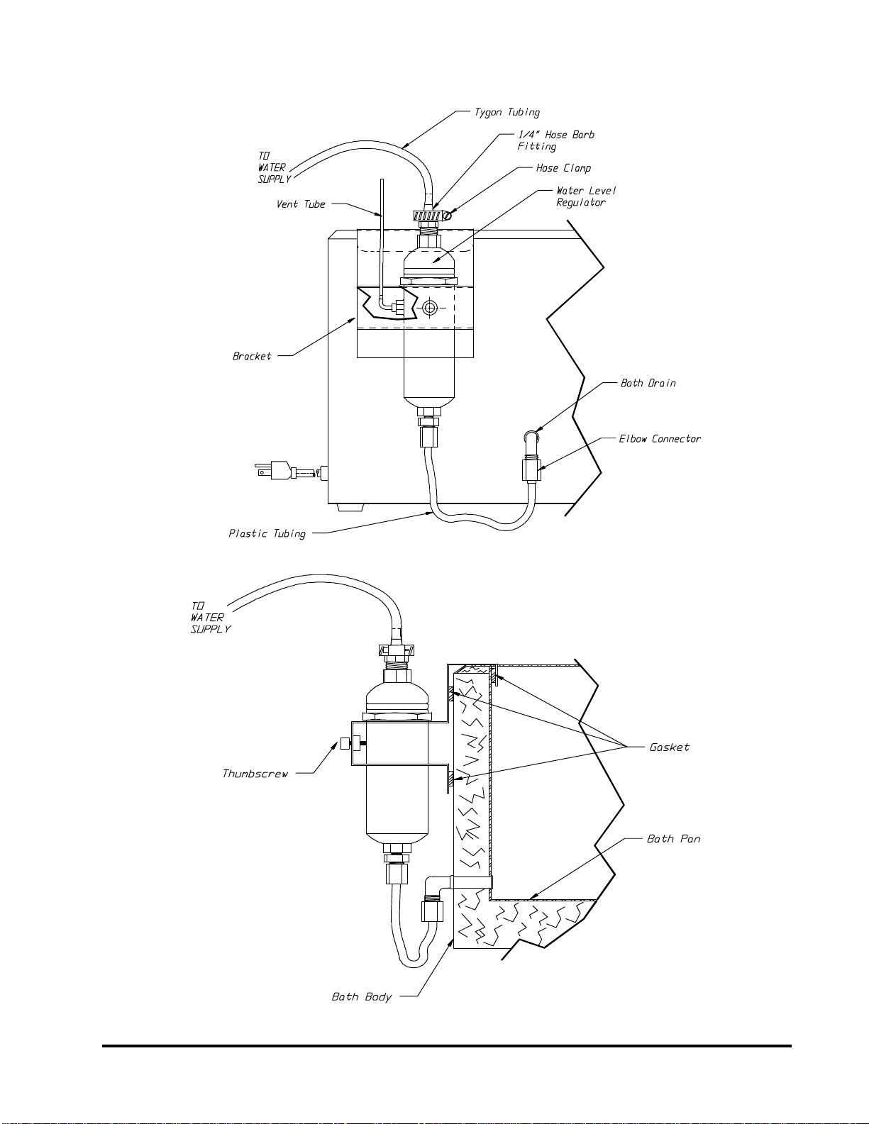
WATER LEVEL REGULATOR
(OPTIONAL)
INSTALLATION INSTRUCTIONS - Use the
followingstepsalongwithFig.1&2shownonthe
followingpage.
1. Turn off unit, disconnect power & drain water
fromthe bath.
2. Unscrew drain plug from side of bath body.
3. Replacewithelbowconnector(shippedloose).
NOTE
TO INSURE GOOD SEAL, WRAP THREADS
WITHTEFLONTAPEOREQUIVALENTSEALER.
4. Tighten elbow connector so open end (tube
fitting)facesstraightdown.
5. PlaceWaterLevelRegulatorBkt.Ass'yonthe
lip of the bath pan (drain side of the bath
towardstherearoftheunit).Thesmallflange
with gasketing near the top of the bracket
shouldrestagainsttheinsideofthebathpan.
Theother2flangeswithgasketingshould rest
againsttheoutsideofthebathbody.
6. Insert the plastic tubing (coming from the
bottom of the water level regulator) into the
elbow connector (at the drain) & tighten the
elbowconnectorfittingfirmlytoinsureagood
seal.
7. Uncoil Tygon tubing & press onto 1/4" Hose
Barb Fitting (located at the top of water level
regulator).
8. Hook-upotherendofthetygontubingtowater
supply&turnonwater.(Waterpressureshould
fall within the following range: MIN is approx.
15 PSI, MAX is approx 75 PSI)
NOTE
WATERLINEMARKINGONTHEWATERLEVEL
REGULATOR IS AN INDICATOR OF THE
APPROX. WATER LEVEL THAT WILL BE
MAINTAINED IN BATH. THE ASS'Y HAS BEEN
SETTOMAINTAINAPPROX.1-3/4"OFWATER.
TO RAISE THE SET WATER LEVEL, LOOSEN
THUMBSCREW & RAISE WATER LEVEL
REGULATOR TO DESIRED LEVEL (COINCIDE
WITH WATER LINE MARK) & TIGHTEN
THUMBSCREW TO HOLD WATER LEVEL
REGULATORINPLACE.
NOTE
DO NOT OVER-TIGHTEN THUMBSCREW
5
WATER LEVEL REGULATOR ASSEMBLY
FIGURE 2
CUTAWAY FRONT VIEW OF BATH
FIGURE 1
SIDE VIEW OF BATH
6
pq
Set Point
Actual
BathTemp., °C
Speed,RPM
Speed,RPM
BathTemp., °C
START/STOP
SELECT/ENTER
Temp.
Offset
HeaterOn
Shaker
PressSELECT/ENTERagain to setthenew value.
PressSELECT/ENTER button toset point.
PressSTART/STOP tobegin or end shaking.
Press or untilvalue is displayed.
Toadjust temperature orshaking speed :
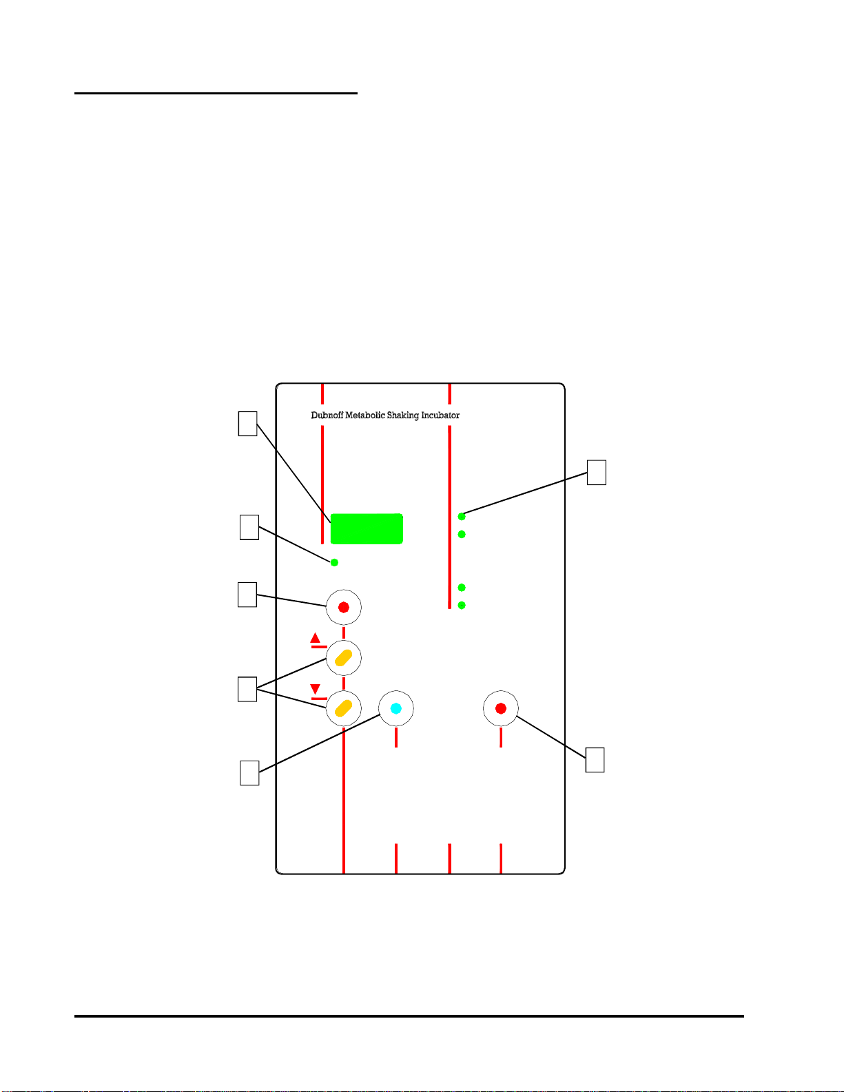
FIGURE A
3
7
5
4
6
2
1
EXPLANATION OF CONTROLS
Power Switch - The power switch is located on
the lower right hand side of the bath, it provides
power for the entire unit.
Hi-LimitThermostat-TheHi-LimitThermostatat
is located immediately to the left of the power
switchonthelowerrighthandcornerofthebath.
The high limit thermostat provides prevention of
heaterrunawayintheeventoftemperaturecontrol
failure.
The Control Panel
islocatedontop
ofthe bath.
1. LEDDisplay-The
three-digit LED
display is used
toshowboththe
actual and
setpoint values
for temperature
and shaking
speed.
2. HeaterOnLamp-
The "Heater
ON" lamp is
illuminated
when power is
applied to the
heater.
3. Indicator Lamps - These lamps indicate
which of 4 parameters (Actual Temp, Actual
Speed,SetpointTemp,andSetpointSpeed)
is displayed in the LED window.
4. Enter Key - The Enter Key is used to choose
which parameter is displayed in the LED window,
and is also used to store a new setpoint value.
5. UP & DOWN Keys - are used to adjust
temperature
andspeed
setpointvalues.
Pressing &
holdingthese
keys will
increment/
decrementthe
displayvalue
slowly at first,
and then rapidly
ifheld.
6. Offset Key-
is used to
adjustthe
temperature
to match a
calibrated
reference
thermometer.
7. Shaker
Start/ Stop Key
-This key is
usedto toggle
the tray shaking
motion on or
off.

7
OPERATION CAUTION
EXERCISE CARE WHEN USING ACIDIC OR
CAUSTIC SOLUTIONS AS THEY WILL ATTACK
THEGALVANIZEDSTEELBATHBODYIFSPILLED
INTOTHEBATH.IFSPILLSDOOCCUR,THEBATH
LIQUIDSHOULDBEIMMEDIATELYDRAINEDAND
THE UNIT THOROUGHLY FLUSHED. SPILLS AND
CONDENSATION SHOULD BE CLEANED/
REMOVED FROM ALL METAL SURFACES AFTER
EACH USE.
Whenfillingthebathwithwater,allowancemustbe
madeforthedisplacementofwateruponimmersion
of samples. Also make allowance for splashing of
water from tray oscillation movement.
CAUTION
WATER LEVEL REQUIREMENTS:
MINIMUMLEVEL-ONEINCHOFWATERSHOULDBE
MAINTAINED AT ALL TIMES. THIS LEVEL WILL
KEEP HEATERS COVERED AND WILL HELP
PREVENTHEATERFAILURE.
MAXIMUMLEVEL-WATERLEVELSHOULDBEKEPT
LOWER THAN THE TRAY SHAFT FITTING. WATER
FILLED BEYOND THIS LEVEL COULD POSSIBLY
SEEPINTOCONTROLPANELANDCAUSEDAMAGE.
To conserve energy, reduce evaporation, and
increase temperature control accuracy, use the
gablecover provided.Donot usealuminumfoil as
a cover, as it may cause corrosion due to an
electrochemical reaction.
1. Add distilled water to bath. Use water levels
as instructed above.
2. Power up: Depress the power switch located
atthelower righthandcorner ofthebath. The
unit is fully operational upon application of
power, and the display will read actual bath
temperature.
3. To set temperature control point:
a. PressENTERuntilsetpointtemperatureis
displayed.
b. Press UP or DOWN until desired setpoint
is displayed.
c. Press ENTER again to set the new value.
d. Display will return to actual temperature.
e. If ENTER is not pressed, new values will
not be set and display will return to actual
temperature.
4. To set new speed:
a. Press ENTER until setpoint speed is
displayed.
b. Press UP or DOWN until desired speed is
displayed.
c. Press ENTER again to set new speed.
d. Display will show actual speed for 10
seconds,thenreturntoactualtemperature.
e. If ENTER is not pressed, new values will
not be set and display will return to actual
temperature.
5. To begin or end shaking motion:
a. Press START/STOP key.
6. To set temperature offset:
a.Temperatureoffsetshouldbeusedtomatch
a stable bath's actual temperature display
to a calibrated thermometer. The offset
valueisenteredasthe
difference
between
the two values.
b. Press ENTER until actual temperature is
displayed.
c.WhilepressingOFFSET,pressUPorDOWN
keys to desired value. Continue holding
offset and press ENTER to set new value.
d. IfENTERisnotpressed,newvalueswillnot
be set and display will return to previous
temperature value.
e. Display should now match your calibrated
thermometer.
f. Temperature setpoint will now control at
previous setpoint plus offset value.
g. Repeatstep3toreadjustsetpointtodesired
value.
h. Example:Setpointis37°andactualdisplay
bathtemperatureisstableat37°.Calibrated
referencethermometerreads37.2°.Press
OFFSETandtheUPkeyuntildisplayreads
.2.PressENTERwhilestillholdingOFFSET
key. Release keys. Display and Setpoint
willnowbe 37.2. Readjust setpoint to 37°.
NOTE
AS WATER BATHS ARE OPERATED, ESPECIALLY
AT ELEVATED TEMPERATURES, CONDENSATION
WILL FORM ON THE UNDERSIDE OF THE GABLE
COVER.THEAMOUNTOFCONDENSATIONCANBE
CONSIDERABLE. CARE SHOULD BE EXERCISED
WHEN REMOVING THE COVER SO THAT WATER
WILL FALL BACK INTO THE BATH CHAMBER, AND
NOTONTHEBATHSURFACE.THECOVERSHOULD
BE PLACED UPSIDE DOWN WHEN REMOVED TO
MAINTAIN A DRY WORK AREA.

8
CAUTION
Never use the following chemicals.
-Aqua Regia -Ferric Chloride
-Iodine -Sodium Azide
-Sulfuric Acid
Removing Discoloration: Should the stainless
steeleverbecomediscoloredbyironrust,usethe
followingproceduretoremovealltracesoftherust
and restore the stainless steel.
WARNING
OBSERVE THE FOLLOWING SAFETY
PRECAUTIONS! USE HEAVY GLOVES OR
OTHER ADEQUATE HAND PROTECTION.
WEARGOGGLESOROTHERADEQUATEEYE
PROTECTION. WORK ONLY IN AREAS WITH
ADEQUATEVENTILATION.
Prepare a solution of 20% nitric and 1.5%
hydrochloricacid(ifpreferred,a2%to5%solution
ofwarm oxalicacid maybeused). Swab solution
over surface, allowing it to remain until all rust is
loosened. This will usually take 1 to 2 minutes.
Assoonasrustisloosened,immediatelyflushwith
clean distilled water until all acid is removed.
MAINTENANCE
OPTICAL DISC - Check the optical disc monthly.
Verifythattheopticaldiscisfreeofforeignmaterial.
Ifnot,wipediscclean.Rotatediscbyhandoneturn
clockwiseandverifythatdiscdoesnotrubagainst
optical sensor; loosen 2 set screws on eccentric
and reposition disc, if required.
CLEANING -Stainless steel will resist corrosion;
however, it is not impervious to it. Proper
maintenance of the stainless steel bath chamber
willhelpassuremanyyearsofservice. Itshouldbe
cleanedregularlywithmildsoapywaterandrinsed
with distilled water. Should algae or other
undesirablemicroorganismsformonthetopofthe
bathmedia,addalittleformaldehydeorquaternary
ammonium germicide available from Precision,
P/N51200912.
CAUTION
AVOID SPILLING HARSH CHEMICALS ONTO
THEBATHASCORROSIONOFTHESTAINLESS
STEELMAY RESULT.
IMPORTANT
IFITISNECESSARYTOUSETHEFOLLOWING
CHEMICALS, LIMIT THE TIME TO A MAXIMUM
OF FOUR HOURS. CLEAN SURFACES
IMMEDIATELYAFTERUSE.
-Aluminum Chloride -Barium Chloride
-Bichloride of Mercury -Calcium Chloride
-Carbolic Acid -Chlorinated Lime
-Citric Acid (boiling) -Dakin's Solution
-Ferrous Chloride -Mercury Salts
-Lysol Mercuric Chloride -Phenol
-Potassium Permanganate -SodiumHypochlorite
-Potassium Thiocyanate -Tartaric Acid
-Stanous Chloride

9
TROUBLESHOOTING 4. Turn ON the main power.
5. The voltmeter should be reading
approximately 14 volts DC ±2.
6. Connect the positive lead to TP3 ±5V. The
voltmetershouldbereading+5voltsDC±0.5.
7. Turn OFF main power. Change the scale of
the voltmeter to 200 VDC. On later versions
of the POWER SUPPLY board there is a
jumper JP1, located near the transformer,
thatmustbeinstalledtomeasurethefollowing
voltage.
8. Connect the negative lead of the meter to
anode (non-stripped end) of CR6 and the
positiveleadtothecathode(strippedend)of
CR7.
9. Turn ON the main power and measure the
voltage. The measured voltage should be
between 140 and 150 VDC.
10. Turn OFF the main power.
11. Connect the display board ribbon connector
to the power supply board at J102 and then
repeat steps 3 thru 6. Do not connect the
connectortotheCPUboardatthistime.Ifthe
above voltages are not measured again, the
displayboard has a badcomponentwhich is
loadingdownthevoltages.Ifthevoltagesare
still present, continue on to step 12.
12. Connect the display board ribbon connector
totheCPUboardJ310andrepeatsteps3thru
6. If the above voltages are not measured
again, the CPU board has a bad component
whichisloadingdownthevoltages.Thisboard
will have to be replaced.
WARNING
SERVICESHOULDBEPERFORMEDONLYBYA
QUALIFIEDTECHNICIAN.BEFOREREPLACING
ANY ELECTRICAL OR MECHANICAL
COMPONENTS, UNPLUG THE LINE CORD. IF
ELECTRICAL POWER IS REQUIRED FOR
SERVICE,USEEXTREMECARE.
RefertoProblemsandSolutionsfortroubleshooting
information on the baths. This guide provides the
basic information required to repair the bath.
The following is a list of the tools and instruments
requiredtoperformtheproceduresoutlinedinthe
Troubleshooting"Problems&Solutions"section.
Tools Needed:
•Phillips or Flat Blade Screwdriver
•7/16" Socket or adjustable wrench
•Ohmmeter
•DCVoltmeter
•ACVoltmeter
•5VDC Power Supply
When changing circuit boards, please use
CAUTION when re-installing the flat cable
connectors that come from the display board.
MakesurethepinsareNOTbentorbroken. Circuit
boardswillnotoperatecorrectlyifthesepinshave
been abused because they will not receive the
necessary signals from other boards.
Before attempting any troubleshooting for a
particular problem, it is good practice to verify
power supply voltages of the POWER SUPPLY
board #34372501. Read these steps to get
acquaintedwiththeprocedure.
1. BesurethatthemainpowersourceisOFFor
disconnected.
2. Insure that J101 and J105 are connected to
the POWER SUPPLY BOARD. Disconnect
J102 that comes from the CPU and the
DISPLAY at this time.
3. Connectthenegativeleadofthevoltmeterto
TP2-COM. SelectaVDCof20. Connectthe
positive lead to TP1 - UNREG.

10
TP1-COMtestpoint. Measurethevoltageat
U7-pin2. Itshouldbeapproximately14volts
DC. ThenmeasurethevoltageatU7-Pin6.
Itshouldbeapproximately5voltsDC. Ifthe
14voltsispresentbutnotthe5volts,theCPU
boardmust bereplaced.
4. Checktemperatureprobe.
a. Measure the bath water temperature and
makenoteofit. Makesureitwillnotchange
drasticallyduringthischeck.
b. WithaDCvoltmeter,measurethesupplyof
thetemperaturesensoratJ302pins1&3. It
shouldbeapproximately5volts. Ifitis,then
continue on to step C. If not, see Step 3a.
c. Measuretheoutputofthetemperaturesensor
atJ302pins2&3.Pin3beingthereference
orground.Theoutputrelationshipofvoltage
to degrees centigrade is listed in the table
below. Compare the measured voltage to
the temperatures listed to determine if the
probe is working.
5. The bath is not heating when it should be
requesting heat. Voltage measurements are
made on the POWER SUPPLY BOARD
#34372501.
a. Select a setpoint temperature at least 10°
above what the actual temperature is. The
bathshouldberequestingheatasindicated
bytheheater"ON"indicatorlamponthefront
panel. It should be on continuously, not
flashing.
b. MeasurethevoltageatU1-PIN2withrespect
toTP2-COM. Itshouldbenogreaterthan4
VDC.
c. MeasuretheDCvoltageacrossR4,sincethe
bath is requesting heat, there should be
currentflowing through this resistor making
the voltage drop equal to 3 vdc ±0.5.
GENERALINFORMATION-ThePOWERSUPPLY
PCB ASSEMBLY #34372501 has the triac (solid
state AC voltage switch) on it which supplies the
power to the heater. This triac is "told" to operate,
whenneed be, by the microprocessor.
There is another device known as an octo-coupler
whichservesasthehigh/lowvoltageisolatorbetween
thetriac and themicroprocessor.
When the bath starts experiencing temperature
problem and/or variations, due to known controller
malfunctioning,thesetwocomponentsbecomeprime
suspects. The reason being they are under higher
operatingstressthanothercomponents.
If thebathstartsexperiencingtemperatureproblems
such as no heat, or "creeping" upward heat, then
follow thetroubleshootinginstructionsbelow. These
instructionsrequiretheuseofavoltmeterbeingable
tomeasureDCandACvoltages(preferablyadigital
voltmeter).
WARNING
THE FOLLOWING TROUBLESHOOTING
INSTRUCTIONSREQUIRETHATPOWERBEON.
ONLY QUALIFIED SERVICE PERSONNEL
SHOULDPERFORMTHESEPROCEDURES.
Openthecontrolcoverandfamiliarizeyourselfwith
thePOWERSUPPLYassembly#34372501. Locate
the triac (Q2), the opto-isolater (U1), the resistor
(R4), andlocatethetestpoint#2(TP2-COM). The
firstmeasurementswillbeDCvoltagemeasurements,
a DC scale of at least 10 volts should be selected.
PROBLEMS & SOLUTIONS
*********** Problem A : No Heat *************
1. Verify that the setpoint temperature is greater
thantheactualwatertemperature.
2. VerifythattheHIGHTEMP lightis"OFF". Ifthe
light is "ON", turn the HIGH LIMIT CONTROL
fullyclockwise.
3. Check temperature probe voltage reference.
These measurements are on the CPU board
#34372801.
a. PlacethenegativeleadofaDCvoltmeteron
Temp
Degrees C Volt Temp
Degrees C Volt
10 0.500V 60 1.400V
20 0.680V 70 1.580V
30 0.860V 80 1.760V
40 1.040V 90 1.940V
50 1.220V 99 2.218V

11
d. If the last two steps are not as stated, then
most likely the CPU board is bad and it will
havetobereplaced.Iftheyare,continueon.
e. Switch the voltmeter to an AC volts scale
capableofreading120volts.
f. MeasurethevoltagebetweenU1-PIN4and
U1-PIN 6. It should be less than 1 VAC.
g. Ifitisnot,thenmostlikelytheopto-couplerU1
isbadand the POWER SUPPLY board will
have to be replaced. If it is, continue on.
h. Measure the voltage directly across the
heater. Itshouldbelinevoltage 110VACto
120VAC.
iIfitisnot,thenmostlikelythetriacQ2isbad,
andthePOWERSUPPLYboardwillhaveto
bereplaced.
6. Checkheater.
a. Disconnectthebathfromitselectricalsupply.
b. Isolate the heater from any circuitry by
disconnectingoneoftheheaterleads.
c. Using an ohmmeter, check the heater
resistance. Appropriate heater resistance
valuesare listedbelow:
If the resistance reads 0 or infinity, then
replacetheheater.
d. Check the resistance between the heater
leads and ground (green wire). If the
resistancereads0ohms,replacetheheater.
********* Problem B: Constant Heat **********
1. Bathis heating when it isnotrequesting heat.
a. Select a setpoint temperature at least 10°
below the actual temperature. The bath
should not be requesting heat as indicated
by the HEATER ON indicator lamp on the
frontpanel. ItshouldNOTbeoncontinuously
orevenflashing.
b. MeasurethevoltageatU1-PIN2withrespect
to TP2-COM. It should be no less than 4
VDC.
c. Measure the DC voltage across R4. The
voltageshouldbeapproximatelyzerovolts.
d. IfthelasttwostepsareNOTasstated,then
most likely the CPU board is bad and it will
havetobereplaced,otherwise,continueon.
e. Switch the voltmeter to an AC volts scale
capableofreading120volts.
f. MeasurethevoltagebetweenU1-PIN4and
U1-PIN6. Itshouldbelinevoltage110VAC
to120 VAC.
g. If it is not, most likely the opto-coupler U1 is
bad and the POWER SUPPLY board will
have to be replaced. If it is, continue on.
h. Measure the voltage directly across the
heater.It should beapproximately0 VAC.
i. Ifitisnot,thenmostlikelythetriacQ2isbad,
andthePOWERSUPPLYboardwillhaveto
bereplaced.
2. Check Temperature Probe. Problem A, Step 4.
115 VOLT 230 VOLT
Dubnoff &
Shallow Form
Shaking Baths 15 OHMS 57 OHMS

12
*** Problem C: Unstable Temperature ***
Control or Display
1. Use gable cover provided to improve
temperaturecontrol.
2. Ifcontrol isstablebutnotatdesiredtemperature,
thenchecktemperaturecalibration.Re-adjustif
necessary.
3. Check Temperature Probe, Problem A, Step 4.
** ProblemD: Display Reads NNNN orUUUU **
The control boards have the ability to detect an
OPENorSHORTEDtemperaturesensor. These
twoconditionsareshownonthedisplayasfollows:
DISPLAY CONDITION
Before coming to the conclusion that the probe is
badwhenoneofthesedisplaysappear,checkthe
connection of the probe to the circuit board for
polarityandalignment.
**ProblemE: DisplayReadsallEights(8888) **
1. Themostcommoncauseof thisproblemisthe
failure of the driver integrated circuit on the
DISPLAY/KEYBOARD board (#34373101).
Replaceit.
*** ProblemF: MotorDoesNotShakeTray ***
1. Verify that the speed setpoint is greater than 0.
2. Later versions of the POWER SUPPLY board
haveajumperJP1locatednearthetransformer.
Verify thatthis jumper isinstalledif applicable.
3. Press the Start/Stop key. If the tray shakes
violentlyforafewmomentsthenstops,replace
theoptical sensor.
4. Check tray linkage for binding.
a. Remove tray from the bath.
b. Disconnectthepushrodfromeccentricby
removingthe bolt.
SHORT CIRCUIT
OPEN CIRCUIT
c. Slidethepushrodbackandforth. Thepush
rodshouldslideveryeasilyinitshousing. If
not, replace the push rod and the bearing
housing.
5. Checkmotor.
a. Disconnect motor connector J103 from the
powersupplyboard.
b. Usinganohmmeter,measuretheresistance
between the black leads (Pins 3 & 4). The
resistance should be approximately 1300
ohms.
c. Usinganohmmeter,measuretheresistance
between the blue leads (Pins 1 & 2). The
resistance should be approximately 130
ohms.
d. Ifneitheroftheaboveresistancesarenotas
stated,replacethemotor.
e. Checktomakesurethereisanopencircuit
between any combination of black and
blue leads. If a resistance is measured
between any black and blue combination,
replace the motor.
6. Check the DISPLAY board #34373101. Even
thoughthischeckisfortheDISPLAYboard,the
voltage measurements will be made on the
POWERSUPPLYboard. Thecommandsignal
thatdrivestheoutputcircuitforthemotorcomes
fromthe displayboard.
a. Be sure the main power is "OFF".
b. PlacethenegativeleadofaDCvoltmeterto
TP2-COM and the positive lead of the
voltmeter to the lead of R6 closer to J102.
Disconnect the motor from the POWER
SUPPLYboardbydisconnectingJ103.
c. Turn"ON"themainpowerandselectaspeed
of200.
d. During normal operation, the voltage at R6
shouldbe about4.4volts DCwith the motor
"OFF". Press the START/STOP key. For
normal operation, this voltage will start to
reducetoabout2.3voltsDCinapproximately
15 seconds and then jump back to 4.4 volts
DCandremainthereuntiltheSTART/STOP
key is pressed again.

13
e. Ifthissignal is NOT changing as mentioned
above when the START/STOP key is
pressed,thenmostlikelytheproblemisinthe
DISPLAYboardanditwillhavetobereplaced.
f. Re-connect the motor back to J103 on the
POWERSUPPLYboard.
7. Check Power Supply Board #34372501.
a. If Step 6 has checked out fine, then possibly
the power circuit for the motor has failed.
Locate the diode CR11 on the POWER
SUPPLY board and place a DC voltmeter
acrossitwiththepositiveleadonthecathode
(band side) and the negative lead on the
anode. The listed voltages appear across
the diode for different speeds. Select a
couple of these speeds and verify the
voltages.
*Problem G: Motor Speed Erratic or Fully on *
1. Check Optical Disc.
a. The optical disc should be free of foreign
material. Ifnot,cleandisc.
b. The disc should be parallel to the bottom of
thebath and centeredin the opticalsensor.
If not, loosen the 2 set screws on eccentric
andreposition thedisc.
c. Thediscshouldbesmoothandflat. Ifthedisc
is bent or warped then replace the disc.
d. Whilethemotorisoperating,thediscshould
NOTcomeincontactwiththeopticalsensor
at any time.
2. CheckOpticaltransmitter.
a. ConnectthenegativeleadofaDCvoltmeter
to TP1-COM on the CPU board.
b. Withthebath"ON"andmotor"OFF"or"ON",
use the positive lead of the voltmeter to
measure the voltage at J303-Pin 1 of the
CPU board. The correct reading should
approximatelybe1.2voltsDC. Ifthereading
deviatesconsiderablyfromthis,replacethe
opticalsensor.
3. CheckOpticalSensor.
JustastheOpticalDisccanbedirty,thelenses
of the optical transmitter and sensor can also
accumulate dust and dirt. It would be good
practice before making the following voltage
measurements to be sure these lenses are
clean. Thelensesarelocatedontheinnerwalls
ofthesensor.
a. ConnectthenegativeleadofaDCvoltmeter
to TP1-COM on the CPU board.
b. ConnectthepositiveleadoftheDCvoltmeter
totheleadofR4whichisclosertotheedge
ofthe circuitboard.
c. Turn the bath power "ON" and the motor
"OFF".
d. Turn the optical disc slowly by hand until a
darkportionofthedisciscenteredbetween
the optical sensor. The voltmeter reading
should be greater than 4 volts DC.
e. Repeat Step D so a clear portion of the disc is
centered between the optical sensor. The
voltmeter reading should be less than 1 volt DC.
f. If the last two steps did not read correctly,
thenreplacetheopticalsensor.
4. Check Display Board #34373101; Problem E,
Step6.
5. Check Power Supply Board #34372501;
Problem E, Step 7.
SPEED SELECTED VOLTAGE ACROSS
CR11
VOLTS DC
30 20
50 30
70 40
90 50
110 60
130 70
150 80

14
Beforeremovinganypartsforreplacement,verify
partinquestionbyfollowingtheinstructionslisted
inthetroubleshootingguide.
Refer to Parts Replacement Table below for
appropriate replacement procedures. Failure to
follow parts replacement procedures may cause
damagetothe bath.
PARTS REPLACEMENT
NOTE: For easiest access to the control housing, place bath on the edge of a bench or table. Remove four
screws on upper side of control housing and carefully lower hinged control panel to the vertical position.
PARTS REPLACEMENT
WARNING
BEFORE REPLACING ANY PART, BE SURE
BATH IS DISCONNECTED FROM POWER
SOURCE. SERVICESHOULDBEPERFORMED
BYAQUALIFIEDTECHNICIAN.
CAUTION
WHENREPLACINGTEMPERATURESENSOROR
HEATER, MAKE SURE ALL SEALS ARE
WATERTIGHTBEFOREAPPLYING ELECTRICAL
POWER.
1. Remove connector J103 from power supply board.
2. Remove bolt on top of plastic bearing and remove bearing.
3. Remove 2 screws from optical sensor and remove sensor.
4. Loosen 2 socket set screws from motor drive eccentric and
remove eccentric from motor shaft.
5. Remove 4 screws holding bracket to wall,
then remove 4 screws holding motor to wall.
6. Reverse above procedure to install new motor.
1. Remove tray from bath.
2. Remove connector J302 from CPU board.
3. Remove temperature sensor fitting from inside bath pan.
-Hold small nut on fitting firmly with a wrench.
-Remove large fitting piece with another wrench.
4. Remove rubber grommet from temperature sensor.
5. Carefully slide sensor through the control housing and remove.
6. Reverse above procedure to install new temperature sensor.
7. Recalibrate new temperature sensor. See Temperature
Recalibrationonpage17.
Replace Temperature
Sensor
1. Remove connector J303 from CPU board.
2. Remove 2 screws holding optical sensor to bracket and remove
sensor.
3. Reverse above procedure to install new sensor.
ReplaceMotor
Replace Optical Sensor

15
PARTS REPLACEMENT (CONT'D)
1. From inside control housing, remove 2 nuts and disconnect
wires from heater leads.
2. Remove two hex nuts from heater ends using a 13/16" socket
and remove heater
3. Reverse above procedure to install new heater.
1. Remove four leads from thermostat terminals.
2. Remove two screws from thermostat bracket and remove
bracket.
3. Carefully tilt bath on its side.
4. Remove eight screws from bottom plate and remove plate.
5. Remove insulation from bottom of pan and between pan
andcontrolpanelwall.
6. Loosen two nuts from thermostat bulb bracket.
7. Carefully remove thermostat from control housing by sliding
bulb through hole in control panel wall.
8. Reverse above procedure to install new Hi Limit thermostat.
Use extreme care when installing new thermostat. A sharp
bend in the thermostat capillary will crimp off flow of
hydraulicfluid.
1. Remove connectors J101, J102, J103, and J105 from board.
Use extra care when removing J102 to not bend connector
pins.
2. Remove five nuts from board and remove board.
3. Reverse above procedure to install new power supply board.
1. Remove bolt on top of plastic bearing and remove plastic
bearing.
2. Disconnect tray from push rod and remove push rod.
3. Remove jam nut from control side of bearing assembly.
4. Slide bearing assembly out and into bath side of unit.
5. Remove bearing cap and wiper seal from assembly.
6. Reverse above procedure to install new bearing assembly.
1. Remove connectors J302 and J303 from CPU board.
2. Remove connector J102 from power supply board. Use
extreme care when removing J102 to not bend connector pins.
3. Remove 4 nuts from CPU board and remove CPU board and
Keyboard/Displayboard.
4. Remove J301 from CPU board. Use extreme care when
removing J301 to not bend connector pins. Remove board.
5. Reverse above procedure to install new board.
Replace Heater
Replace "HI Limit"
Thermostat
Replace Power Supply
Board
ReplaceBearing
Assembly
Replace CPU or Display/
KeyboardBoard
See note on the following
page **

16
PARTS REPLACEMENT (CONT'D)
6. The software must be configured to match the Bath model.
To enter configuration mode, press the upper left pushbutton
while applying power. The upper left push-button is labeled
"Select/Enter." This push-button is used to enter configuration
codes and steps through the different levels of configurations.
When a triangle is shown in the chart, the pushbutton is to be
depressed once for each symbol.
Immediately following power up with the push-button
depressed,the readout will display a 3-digit number. This is
the software revision. The readout will then begin to do a self-
test of digits. Press the "Calibrate" push-button once. The
readout will display 0000. Follow the listing below to complete
theconfiguration.
A. Enter 37 using up/down arrows. Press "Select/Enter"
B. Enter 12 using up/down arrows. Press "Select/Enter"
C. Enter 2.0 using up/down arrows. Press "Select/Enter"
D. Enter 500 using up/down arrows. Press "Select/Enter"
E. Enter 1 using up/down arrows. Press "Select/Enter"
F. Display Not Used. Press "Select/Enter"
G. Display Not Used. Press "Select/Enter"
H. Display will show raw count Press "Select/Enter"
I. LOW TEMP CALIBRATION*
LITTLEc.FactorySetting. Press "Select/Enter"
J. HI TEMP CALIBRATION
BIG C. Factory Setting. Press "Select/Enter"
Configuration is now complete
Replace CPU or
Display/Keyboard Board
See note below **
* Calibration of the low and high end of the sensor input is done at the factory. Field calibration of
the sensor may be performed using the following technique: Enter the configuration routine and
press the top left switch until a little "c" (Item H) is displayed. Add water that is around 10°C to the
bath completely covering the sensor. Insert a calibrated thermometer. After the thermometer
stabilizes, match the display setting to the thermometer reading by pressing the "UP" or "DOWN"
push button switch. Press the top left switch. The readout will now display a big "C" (Item I).
Remove water from the bath and add hot water of about 70 - 80°C. After the unit stabilizes, match
readout display to temperature on thermometer and press the top left switch. Calibration is now
complete.
**Note:
When replacing CPU printed circuit board reprogramming may be necessary.
Follow thoroughly instructions provided with the replacement circuit board.
This manual suits for next models
3
Table of contents
Other Precision Laboratory Equipment manuals


