Precision 180 Manual

Installation/Service Manual
General Purpose Water Baths
Models 180, 181, 182, 183,
184, 185, 186, 188
Precision
170 Marcel Drive
Winchester, VA
USA
Phone: 540-869-8623
Toll Free: 800-621-8820
FAX: 540-869-8626
ManualP/N36100124(34002480)
RevBDated08NOV01
10
2
1
0
3
46
5
882
1
9
0
9
10 Off
73
5
4
7
6On

NOTICE
THE MATERIAL IN THIS MANUAL IS FOR INFORMATION PURPOSES ONLY. THE CONTENTS
AND THE PRODUCT IT DESCRIBES ARE SUBJECT TO CHANGE WITHOUT NOTICE.
PRECISION MAKES NO REPRESENTATIONS OR WARRANTIES WITH RESPECT TO THIS
MANUAL. IN NO EVENT SHALL PRECISION BE LIABLE FOR ANY DAMAGES, DIRECT OR
INCIDENTAL, ARISING OUT OF OR RELATED TO THE USE OF THIS MANUAL.
For repair information or replacement parts assistance from the manufacturer,
call Customer Service using our toll free telephone number.
800-621-8820
(FAX) 540-869-0130

Initialrelease
6/99A
INDEX DATE AMENDED PAGES NOTES
REVISION STATUS
Update specs
11/01B2

Contents
1. Introduction .................................................................................................................... 1
2. Unpacking and Damage................................................................................................. 1
3. Specifications ................................................................................................................. 2
4. Installation ...................................................................................................................... 3
5. Operation ........................................................................................................................ 3
6. Maintenance.................................................................................................................... 6
7. Service ............................................................................................................................ 8
8. Replacement Parts List................................................................................................ 10
9. Assembly and Schematic Drawings ........................................................................... 11
10. Warranty ...................................................................................................................... 14

1
1. INTRODUCTION
Precision General Purpose Water Baths are
designed for a wide variety of serological research
procedures as well as a broad range of other
general laboratory applications. Operation and
maintenance of these baths are covered in this
manual; unless specifically noted otherwise, the
informationprovided appliestoall availablemodels.
Precision water baths feature a one-piece, deep-
drawn stainless steel chamber with welded and
painted galvanized steel outer body. Depending
onthe model,eitherone ortwoheaters areattached
to the bottom of the bath chamber. For faster
temperature recovery and reduced power
consumption, the baths are equipped with a
stainless steel cover (except Model 181, which is
equipped with a plastic cover). This cover must be
in place to reach and maintain 100°C.
All units (except Model 180) also feature an
adjustable support shelf which may be set at three
different height levels by simply changing the
position of the legs. Model 180 is equipped with a
non-adjustable diffuser shelf.
As the ultimate user of this apparatus, it is your
responsibility to understand its proper function and
operationalcharacteristics. Thisinstruction manual
should be thoroughly read and all operators given
adequate training before attempting to place this
unit in service. Awareness of the stated cautions
and warnings, and compliance with recommended
operating parameters - together with maintenance
requirements - are important for safe and
satisfactory operation. The unit should be used for
itsintended application; alterations ormodifications
will void the warranty.
WARNING
AS A ROUTINE LABORATORY PRECAUTION,
ALWAYS WEAR SAFETY GLASSES WHEN
WORKING WITH THIS APPARATUS.
2. UNPACKING AND DAMAGE
This merchandise was carefully packed and
thoroughly inspected; save all packing material if
apparatus is received damaged.
Responsibility for its safe delivery was assumed by
the carrier upon acceptance of the shipment;
therefore, claims for loss or damage sustained in
transit must be made upon the carrier by the
recipient as follows:
Visible Loss or Damage: Note any external
evidence of loss or damage on the freight bill, or
express receipt, and have it signed by the carrier's
agent.Failure to adequately describe suchexternal
evidence of loss or damage may result in the
carrier's refusing to honor your damage claim. The
form required to file such a claim will be supplied by
the carrier.
Concealed Loss or Damage: Concealed loss or
damage means loss or damage which does not
become apparent until the merchandise has been
unpacked and inspected. Should either occur,
make a written request for inspection by the
carrier's agent within 15 days of delivery date; then
file a claim with the carrier since the damage is the
carrier's responsibility.
If you follow these instructions carefully, we
guarantee our full support of your claim to be
compensated for loss from concealed damage.
DO NOT, FOR ANY REASON , RETURN THIS
UNIT WITHOUT FIRST OBTAINING
AUTHORIZATION. In any correspondence to
Precision Scientific, please supply the nameplate
data, including catalog number and serial
number.

2
3. SPECIFICATIONS
Precision General Purpose Water Baths feature the following parameters. Volume calculations are
based using water level approximately 1" (25mm) from the chamber top.
Catalog
Number Model
Number
Electrical Characteristics Capacity
Volts Watts Amps Liters Gallons
51221070
51221071 180 120
230 225 1.9
1.0 1.5 0.4
51221064
51221211 181 120
230 225 1.9
1.0 2.5 0.7
51221073
51221068 182 120
230 300 2.5
1.3 5.5 1.5
51221060
51221062 183 120
230 400 3.3
1.7 12.0 3.2
51221075
51221069 184 120
230 600 5.0
2.6 19.5 5.2
51221065
51221066 185 120
230 600 5.0
2.6 18.0 4.9
51221072
51221074 186 120
230 1200 10.0
5.2 43.0 11.4
51221061
51221063 188
Dual 120
230 800 6.7
3.5
12.0
Both
Pans
3.2
Both
Pans

3
4. INSTALLATION
4.1 Location
To obtain the most uniform operating conditions
and results, place the bath in an area remote from
drafts,ventilationoutlets, radiators,and otherrapidly
changing ambient conditions.
To assure proper ventilation, allow at least 4" clear-
ance between the rear, top, and sides of the unit and
adjacentwall.Iftwo ormoreunitsarepositioned side-
by-side, allow at least 8" between them.
4.2 Electrical Connections
IMPORTANT : PLEASE READ CAREFULLY.
WARNING:
FOR PERSONAL SAFETY, THIS APPARATUS
MUST BE PROPERLY GROUNDED.
CAUTION:
BE SURE THAT THE POWER SUPPLY IS OF
THE SAME VOLTAGE AS SPECIFIED ON THE
NAMEPLATE.
The power cord of this instrument is equipped with
a three-prong (grounding) plug which mates with a
standard three-prong (grounding) wall receptacle
to minimize the possibility of electric shock hazard.
The user should have the wall receptacle and
circuit checked by a qualified electrician to make
sure the receptacle is properly grounded. Where a
two-prong receptacle is encountered, it is the
personal responsibility and obligation of the user to
have it replaced with a properly grounded three-
prong receptacle.
WARNING:
DO NOT, UNDER ANY CIRCUMSTANCES, CUT OR
REMOVE THE THIRD (GROUND) PRONG FROM
THE POWER CORD. DO NOT USE A TWO-PRONG
ADAPTER PLUG.
Determine the total amount of current presently
being used by other equipment connected to the
circuit that will be used for this unit. It is critical that
the added current demand by this appliance and
other equipment on the circuit not exceed the
rating of the fuse or circuit breaker in use.
5. OPERATION
CAUTION:
EXERCISE CARE WHEN USING ACIDIC OR
CAUSTIC SOLUTIONS AS THEY WILL ATTACK
THE GALVANIZED STEEL BATH BODY IF SPILLED
INTO THE BATH. IF SPILLS DO OCCUR, THE
BATH LIQUID SHOULD BE IMMEDIATELY
DRAINED AND THE UNIT THOROUGHLY
FLUSHED. SPILLS AND CONDENSATION SHOULD
BE CLEANED/REMOVED FROM ALL METAL
SURFACES AFTER EACH USE.
5.1 Shelf Placement
Place the stainless steel metal shelf also called
diffuser shelf, (corners facing downward) inside
the bath chamber. The shelf provides a sample
base and protects samples from touching the hot
metal bath bottom.
If it is necessary to increase the height of the
diffuser shelf, a Leg Extension Kit is included for
this purpose. Model 180 (Catalog #'s 51220070 &
51220071) are excluded.
Following the figure shown below, attach the four
extension legs to each of the four corners of the
diffuser shelf.
DIFFUSER SHELF
LEG EXTENSION KIT

4
5. OPERATION (CONT.)
5.2 Filling Bath
NOTE:
DISTILLED WATER IS RECOMMENDED; IT WILL
NOT CORRODE THE BATH CHAMBER
AND IT REDUCES THE NEED FOR FREQUENT
BATH CLEANING.
DO NOT USE 18 MEG DEIONIZED WATER.
NOTE: If this is the only source of treated water
available; mix 50% with regular tap water.
Before filling, check the power switch and make
sure that it is in the "OFF" position.
Fill the bath with distilled water, making allowance
for displacement by the sample(s) being immersed
and for expansion of the media upon reaching
operating temperature.
For Model 181 and above, the maximum liquid
level should be 1-1/2" from the top surface of the
bath after sample(s) are immersed. For the Model
180, the maximum liquid level should be 3/4" from
the top of the bath.
5.3 Bath Cover
To conserve energy and reduce evaporation, use
the cover supplied with the bath throughout the
temperature range of the bath. This cover must be
in place to reach and maintain 100°C.
CAUTION:
DO NOT USE ALUMINUM FOIL AS A COVER; IT
MAY CAUSE CORROSION OF THE STAINLESS
STEEL AS A RESULT OF AN ELECTROLYTIC
REACTION.
NOTE:
AS WATER BATHS ARE OPERATED,
ESPECIALLY AT ELEVATED TEMPERATURES,
CONDENSATION WILL FORM ON THE
UNDERSIDE OF THE GABLE COVER. THE
AMOUNT OF CONDENSATION CAN BE
CONSIDERABLE. CARE SHOULD BE
EXERCISED WHEN REMOVING THE COVER
SO THAT WATER WILL FALL BACK INTO THE
BATH CHAMBER, AND NOT ON THE BATH
SURFACE. THE COVER SHOULD BE PLACED
UPSIDE DOWN WHEN REMOVED TO MAINTAIN
A DRY WORK AREA.
5.4 Bath Thermometer
Eachbathis suppliedwithathermometer and O-ring
(packed separately).The thermometer isattached to
the bath via a metal clip on the top of the bath.
Slip the O-ring onto the thermometer; insert this
assemblythrough the metal clip until theimmersion
depth indicator line is at or below the water surface.
The thermometer bulb should always be located
above the diffuser shelf.
CAUTION:
CARE SHOULD BE TAKEN TO PROTECT THE
THERMOMETER FROM ACCIDENTAL
BREAKAGE AND SPILLAGE OF CONTENTS.
5.5 Power ON
Insert the line cord into the proper receptacle and
turn the power switch to the "ON" position. This
action will energize the heater and cause the
amber pilot lamp to light. The pilot lamp will stay lit
as long as the heater(s) is energized.
5.6 Setting Thermostats
NOTE:
DIAL NUMBERS ON FRONT PANEL ARE FOR
REFERENCE ONLY; THEY ARE NOT VALUES
FOR WATER TEMPERATURE WITHIN THE UNIT.
WARNING:
DO NOT LEAVE THE BATH UNATTENDED DUR-
ING THE SETTING PROCEDURE.
A. Turn both the Temperature Control and High
Temperature Limit thermostat knobs fully
clockwise. The Temperature Control Pilot lamp
should illuminate.
B. When the bath temperature reaches the desired
temperature, slowly turn the High Temperature
Limit Thermostat counterclockwise and stop
when the High Temperature Limit Pilot Lamp
illuminates.
C. Turn the High Temperature Limit Thermostat
Knobclockwisetonexthighestreferencenumber.
The High temperature Limit light should go off.
The High Temperature Limit thermostat is now
set approximately 5° above the desired bath
temperature.

5
D. Turn the Temperature Control Thermostat
counterclockwise until both pilot lamps are off.
E. Turn the Temperature Control thermostat
clockwise until the Temperature Control pilot
lamp just lights. Allow the unit to stabilize,
readjust/fine tune the Temperature Control
thermostat as necessary.
2II
2Q
Figure 5.1 Controls

6
6. MAINTENANCE
WARNING:
UNIT MUST BE DISCONNECTED FROM POWER
SOURCE PRIOR TO SERVICING. IT IS
RECOMMENDED THAT ALL SERVICE BE
PERFORMED BY QUALIFIED SERVICE
PERSONNEL.
CAUTION:
ELECTROLYSIS CAN DAMAGE STAINLESS
STEEL. THIS CAN OCCUR IF AN OBJECT IS
ALLOWED TO REST DIRECTLY ON THE
SURFACE, TRAPPING MOISTURE THAT
BECOMES OXYGEN STARVED BUT IS
SURROUNDED BY WATER CONTAINING
OXYGEN. THE RESULTING ELECTROLYTIC
ACTION WILL PIT OR CORRODE THE
STAINLESS STEEL.
Background
Stainless steel is an alloy of steel with chromium
and nickel which increase the metal's resistance to
rust and corrosion. However, if not properly cared
for it can rust and corrode. Exposure to air provides
the passivations for clean stainless steel. This
exposureproduces a thin, durable chromium-oxide
film that forms rapidly on the alloy surface and
gives stainless steel its characteristic "stainless"
quality. Exposure of the surface to water other
oxidizing environments also produces this
passivating film. However, if free oxygen is not
available due to scale or contamination buildup the
metal surface may become vulnerable to attack.
Maintaining a neutral pH and frequent cleaning
with detergent and water will give you years of
trouble free service for your water bath. The follow-
ing are some guidelines to keep in mind.
Water
Distilled water is recommended. Maintain pH
between 7 and 9 to minimize corrosion of the
stainless steel.
De-ionizedor reverse-osmosis water may be used.
However, if this water is very pure it may be
corrosive to stainless steel; and in such cases
always add 20-40 ppm (20 to 40 mg/liter)
disodium phosphate or sodium bicarbonate.
Adjust dosage to give a pH of 7 to 9. See "pH
Control" below.
If the above water is not available you may use
clean, aerated soft tap water provided the total
solids concentration is <500 ppm.
pH Control
Be sure to check pH regularly. If pH is <6.0, add
disodium phosphate to increase pH to a 7 to 9
value. Sodium carbonate or sodium bicarbonate
may be used but tend to form scale which must be
rinsed out regularly. If pH is >10.0 add sodium
bisulfate to decrease pH to a 7 to 9 value. Avoid
adding harsh alkalines or acids since they may
cause localized corrosion and result in unstable pH.
Anti-Fungal -- Anti-Bacterial Additives
These additives are permissible to use as long as
the pH of the aqueous solution is kept within the
range of 7 to 9. Some of these are available
through your supply dealer. Be sure they are not
harmful to stainless steel.
Prevention of Scale Buildup
Additives commonly available for use in swimming
pools and spas may be acceptable in circulating
baths only. In static baths these are generally not
effective. This is why it is best to use distilled,
deionized or RO water treated as described in
"WATER" above. If scale buildup is detected
(especially around immersion heaters) clean the
bath and replace water as soon as practical.
Other Water Additives
Proper maintenance of the stainless steel bath
chamber will help assure many years of service.
It should be cleaned regularly with mild soapy
water and rinsed with distilled water.
IMPORTANT: If it is necessary to use the following
chemicals, limit the exposure time to a maximum of
four hours. Clean surfaces immediately after use
by rinsing with distilled water.
Aluminum Chloride Barium Chloride
Bichloride of Mercury Calcium Chloride
Carbolic Acid Chlorinated Lime
Citric Acid (boiling) Dakin's Solution
Ferrous Chloride Mercury Salts
Lysol Mercuric Chloride Phenol
Potassium Permanganate
StannousChloride
Sodium Hypochlorite Tartaric Acid
Potassium Thiocyanate Lysol

7
NEVER USE THE FOLLOWING
Aqua Regia Ferric Chloride Iodine
Sodium Azide Sulfuric Acid
6.1 Cleaning
Spillsof any chemical, especially thoselisted above
should be removed as soon as possible and the
stainless steel surface cleaned with mild soapy
water followed by copious rinse with clean water.
Do not use soap filled or any metallic pads. Even
stainless steel pads are to be avoided as they may
destroy the passive film on the surface of the metal
andcreate crevices thatmay harbor contamination.
If stubborn stains persist use a plastic light duty
cleansing pad and rub gently in the direction of the
metal grain. If stains continue to persist use one of
the following methods.
WARNING:
THE FOLLOWING CHEMICAL METHODS HAVE
PROVEN SUCCESSFUL BUT EXTREME CARE
MUST BE TAKEN WHEN HANDLING THESE
MATERIALS. ALWAYS WORK IN AN AREA WITH
ADEQUATE VENTILATION. USE THE
PRECAUTIONS OUTLINED IN THE MATERIAL
SAFETY DATA SHEET (MSDS) AND
MANUFACTURER'S INSTRUCTIONS FOR THE
PRODUCT YOU ARE WORKING WITH. FOLLOW
THE PERSONAL PROTECTION INDEX FOUND
IN THE HAZARDOUS MATERIALS
IDENTIFICATION SYSTEM (HMIS) SECTION OF
THE MSDS.
THE USE AND DISPOSAL OF THESE
CHEMICALS MAY BE REGULATED BY YOUR
LOCAL MUNICIPALITY. CONSULT THE
REGULATIONS BEFORE DISPOSING OF THESE
MATERIALS.
1. Bathroom tub and tile cleaners. Available at
supermarkets.
2. Any of a variety of "scale removers" available at
your local supermarket or hardware store.
Generally sold for cleaning coffee makers,
humidifiers and vaporizers.
3. Citric acid based cleaners. Contact your lab
supply dealer.
4. A 15 to 35% phosphoric acid solution. Available
from chemical supply dealers for scale and rust
removal. Allow solution to soak the surface
affected until rust and scale is loosened.
Immediatelyrinse withcopious amounts ofclean
water.
5. Oxalic Acid 2% to 5% in warm water. Swab
solution on surface allowing it to remain until
rust is loosened. Immediately flush with copious
amounts of clean water.
6.A mixture of20% nitric acid and1.5% hydrofluoric
acid (or hydrochloric acid). Swab solution on
surface allowing it to remain until rust is
loosened. Immediately flush with copious
amounts of clean water.
The above are ranked in order of mild to strong
cleaning agents. Items 5 and 6 should only be
used if severe rust and scale stains have devel-
oped and cannot be removed by any other method.
In any case the chemical should be allowed to do
the cleaning with minimal scrubbing. Always fol-
low the manufacturer's instructions.
6.2 Chamber Disinfecting
Materials known to be effective in disinfecting:
*Household Bleach
*Glutaraldehyde
*Alcohol
Consult with your staff chemist for advice on
using these chemicals.
CAUTION:
ALWAYS RINSE WITH COPIOUS AMOUNTS OF
CLEAN WATER. AIR DRY AND/OR FILL WITH
FRESH WATER AND FOLLOW THE GUIDELINES
IN "WATER" ABOVE.
DISCLAIMER:
The above information is the result of limited inves-
tigation and Precision Scientific makes no claims
as to the suitability to your particular application.
These are intended to be GUIDELINES ONLY.
Consult your staff chemist to determine what works
best in your lab.
8
7. SERVICE
WARNING:
UNIT MUST BE DISCONNECTED FROM POWER
SOURCE PRIOR TO SERVICING. IT IS
RECOMMENDED THAT ALL SERVICE BE
PERFORMED BY QUALIFIED SERVICE
PERSONNEL.
7.1 General Information
To service the water bath, turn it on its side or top
and remove the bottom plate and insulation. To
prevent scratching of the enameled surface, place
protective material (such as cardboard, cloth, or
newspaper) under unit.
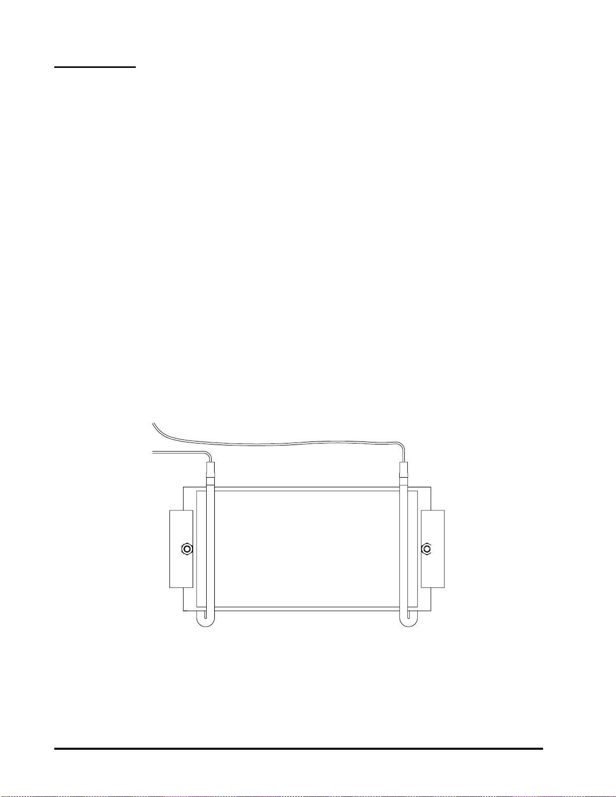
7.2 Heater Element Replacement
A. Put the power switch in the "OFF" position and
disconnect power to the bath.
B. Turn bath upside down and remove bottom plate
& fiberglass insulation
C. Disconnect the two leads from heater element.
D. Remove the two hex nuts that fasten the heater
element to the pan and remove element.
E.Remove FiberFaxinsulation from theold element
and insert it into the new element.
F. Fasten the new heater element to the pan and
connect the two leads.
CAUTION:
BE SURE THE WIRE LEADS DO NOT TOUCH
THE HEATER ELEMENT.
G. Replace insulation and install bottom plate.
NOTE:
USE NO THERMAL COMPOUNDS OR PASTE
ON HEATER.
Figure 7.1 Heater element

9
7.3.1 Thermostat Replacement
Use the following thermostat replacement proce-
dure when the sensing bulb is located WITHIN the
bathpan. Some models only have externally
mounted sensing bulbs on the underside of the
pan, if this is the case follow procedure 7.3.2.
CAUTION:
CARE MUST BE EXERCISED WHEN HANDLING
THE THERMOSTAT CAPILLARY, SINCE A
SHARP BEND WILL CRIMP OFF THE FLOW OF
THE HYDRAULIC OPERATING MEDIUM. TO
AVOID TWISTING THE CAPILLARY OR
DAMAGING O-RING, HOLD THE FITTING
UNDER THE BATH STATIONARY, AND FIRMLY
TIGHTEN LOCKNUT INSIDE BATH CHAMBER.
DO NOT OVER-TIGHTEN, AS O-RING
COULD BE SQUEEZED OUT OF POSITION,
CAUSING BATH TO LEAK. UNDERTIGHTENING
WILL ALSO CAUSE THE BATH TO LEAK.
A. Put switch in "OFF" position and disconnect
power to bath.
B. Remove shelf and drain bath.
C. Remove thermostat control knob by loosening
two set screws on knob.
D. Place bath on its side and remove bottom plate
and insulation to gain access to thermostat
fitting.
E. Remove two screws fastening thermostat to
control panel.
F. Remove wires from thermostat terminals. Mark
location of wire leads.
G.Hold thefittingunder thebath stationary,unscrew
locknut inside bath chamber, and remove from
capillary.
H. Feed thermostat capillary out through hole in
bottom of chamber.
I. Replace O-ring on bottom side of chamber with
new Viton O-ring.
J. Complete installation by reversing above
procedure. Be certain all wiring is away from
heater. Insulation must be replaced between
heater and bottom plate to prevent possible
wire shorting.
7.3.2 Thermostat Replacement
Use the following procedure when the sensing
bulb is located UNDER the pan.
A. Put the power in the "OFF" position and
disconnect power to the bath.
B. Turn bath upside down and remove bottom plate
and fiberglass insulation.
C. Mark the location of the wire leads on the
thermostat and disconnect.
D. Remove thermostat control knob by loosening
two set screws on knob.
E. Remove two screws fastening thermostat to
control panel.
F. Loosen the two hex nuts holding thermostat bulb
bracket and pull the thermostat and bulb out
from behind the control panel.
G. Mount the new thermostat by reversing steps A
through G.
CAUTION:
MAKE SURE THE WIRE LEADS DO NOT TOUCH
THE HEATER ELEMENT.

10
8. REPLACEMENT PARTS
Item
Number Symbol Wiring
Diagram Description Part
Number
1 DS1/DS2 Pilot Light Assembly-Amber (120 VAC)
Pilot Light Assembly-Amber (240 VAC) 34541927
34002320
2 S1 DPST Switch - Amber (115 & 230 VAC) 34240618
3 S2/S3 Thermostat (120/240 VAC) under pan
Thermostat (120/240 VAC) in pan 34239186
34001584
4 HR1/HR2 Heater - Model 180 (120 VAC)
Heater - Model 180 (240 VAC)
Heater - Model 181 (120 VAC)
Heater - Model 181 (240 VAC)
Heater - Model 182 (120 VAC)
Heater - Model 182 (240 VAC)
Heater - Model 183 (120 VAC)
Heater - Model 183 (240 VAC)
Heater - Model 184 (120 VAC)
Heater - Model 184 (240 VAC)
Heater - Model 185 (120 VAC)
Heater - Model 185 (240 VAC)
Heater - Model 186 (120 VAC) QTY2
Heater - Model 186 (240 VAC) QTY2
34247411
34247399
34247411
34247399
34247412
34247346
34247413
34247347
34247414
34247348
34247414
34247348
34247414
34247348
5 n/a Heater Model 188 equal pans 120v (qty2)
Heater Model 188 equal pans 220v (qty2) 34247413
34247347
6 n/a Thermometer - Model 180
Thermometer - All Other Models 34307058
34307059
7 n/a O’Ring, Thermometer 34232070
8 n/a Knob, Thermostat 34220199
9 n/a Bracket, Heater Retaining (2/Heater) 34542262
10 n/a Cord and plug (120 VAC)
Cord and plug (240 VAC) 36353081
34353046

11
WIRING DIAGRAM
MODELS 180-185
9. WIRING DIAGRAMS

12
WIRING DIAGRAM
MODEL 186

13
WIRING DIAGRAM
MODEL 188

14
WARRANTY
PRECISION warrants its products against defects in material and workmanship when used
under appropriate conditions and in accordance with appropriate operating instructions for a
period of no less than one (1) year from the date of delivery of the products.
Sole obligation of PRECISION shall be to repair or replace at our option, FOB factory or locally,
without charge, any part(s) that prove defective within the warranty period, provided the
customer notifies PRECISION promptly and in writing of any such defect. Compensation for
labor by other than PRECISION employees will not be our obligation. Part(s) replacement does
not constitute an extension of the original warranty period.
PRECISION MAKES NO WARRANTY OR MERCHANTABILITY, FITNESS FOR A
PARTICULAR PURPOSE, OR ANY OTHER WARRANTY, EXPRESSED OR IMPLIED, AS
TO THE DESIGN, SALE, INSTALLATION, OR USE OF ITS PRODUCTS, AND SHALL NOT
BE LIABLE FOR CONSEQUENTIAL DAMAGE RESULTING FROM THE USE OF ITS
PRODUCTS.
PRECISION SCIENTIFIC will not assume responsibility for unauthorized repairs or failure as
a result of unauthorized product modifications, or for repairs, replacement, or modification
negligently or otherwise improperly made or performed by persons other than PRECISION
employees or authorized representatives.
While our personnel are available to advise customers concerning general applications of all
manufactured products, oral representations are not warranties with respect to particular
application and should not be relied upon if inconsistent with product specification or the terms
stated herein.
In any event, the terms and conditions contained in PRECISION formal sales contracts shall
be controlling; and any changes must be in writing and signed by an authorized executive of
PRECISION .
All defective components will be replaced without charge one (1) year from the date of delivery.
There will be no charge for labor if the apparatus is returned to the factory prepaid.
Conditions and qualifications of the warranty statement shall prevail at all times.
This manual suits for next models
23
Table of contents
Other Precision Laboratory Equipment manuals


Popular Laboratory Equipment manuals by other brands

Ovation
Ovation QS Cleaning instructions

Beckman Coulter
Beckman Coulter Optima XE Series user guide

Binder
Binder MKF 400 operating manual

TA Instruments
TA Instruments DISCOVERY XENON FLASH Getting started guide

HACH LANGE
HACH LANGE BUHLER 3010 Short manual

Metrohm
Metrohm 930 Compact IC Flex SeS Manual - Short Instructions


