Precision TA500 User manual

Owner’s Manual | TA500 | 40” Spike Aerator
Manual Contents
Safety Instructions .......................................................... 2
Assembly ............................................................................ 4-9
Operation........................................................................... 10
Maintenance ..................................................................... 10
Parts...................................................................................... 2-3
Warranty ............................................................................. 12
Your New Spike Aerator
Congratulations on your purchase of a new Precision
Products Inc. Spike Aerator. Your aerator has been en-
gineered and built to give you the most dependable
and best performing product possible.
If you experience any problem you can not easily re-
solve, please feel free to contact our knowledgeable
and helpful customer service department toll-free at
1 (800) 225-5891.
Caution: Read all Safety Instructions and Operating Instructions Carefully.
Form No. 5570 (Rev. 10/11)

Rules for Safe Operation
All power equipment can cause injury or property damage if operated improperly. Please read and observe the
following safety rules and exercise caution at all times when operating equipment.
• Read and understand your tractor owner’s manual and towing safely rules.
• Never allow children to operate the towing vehicle. Do not allow adults to operate the tractor without having read the owner’s
manual or receiving proper instruction.
• Do not allow anyone to ride or sit on tow behind equipment during operation.
• Keep people and animals at a safe distance.
• Always wear substantial footwear. Do not wear loose tting clothing that may get caught in moving parts.
• This unit may have sharp points. Handle with care.
• Keep your eyes and mind on your vehicle/attachment and area being covered. Do not let yourself be distracted.
• Stay alert for holes in the terrain and other hidden hazards.
• Tractor braking and stability may be aected with the attachment of this unit. Be aware of changing conditions on slopes. Refer to safety rules
in your tractor owner’s manual concerning safe operation on slopes. Stay O Steep Slopes.
• Always operate up and down a slope, never across the face of a slope.
• This equipment should be operated at a reduced speed on rough terrain, along creeks, ditches and on hillsides, to prevent tipping and loss
of control.
• Always begin with the transmission in rst (low) gear and engine at low speed, gradually increasing speed as conditions permit.
• Keep the tractor and attachment in good operating condition and keep safety devices in place.
• Keep all nuts, bolts and screws tight to be sure the equipment is in safe working condition.
• The tractor and attachment should be stopped and inspected for damage after striking a foreign object. Any damage should be repaired
before restarting and operating the equipment.
• Follow the maintenance instructions as outlined in this owner’s manual.
• Do not exceed 3-4 miles per hour.
Carton Contents
2

Hardware Package Contents
34
2726
22
2825
15
16 17
1918
20
21
23 24
13
14
31 33
32
3029
35 36 37
1
2
3
4
5
6
7
8
9
10
11
12
13
14
15
16
17
18
19
20
21
22
23
24
25
26
27
28
29
30
31
32
33
34
35
36
37
Ref. Ref.Qty. Qty.Description Description
1
1
1
1
1
2
1
1
9
1
2
1
2
1
1
1
2
11
5
1
1
1
6
2
1
9
14
2
14
1
2
4
6
14
1
1
2
Base Plate
Tow Bar
Clevis Plate
Handle
Axle Assembly
Wheel Bracket
Lever Link
Link Bar
Tine
Handle Brace
Wheels
Handle Grip
1/2”x 3” Hex Head Bolt
1/2”x 1-1/2” Hex Head Bolt
5/16”x 2-1/4” Hex Head Bolt
5/16”x 1-3/4” Hex Head Bolt
5/16”x 1-1/2” Hex Head Bolt
5/16”x 1” Hex Head Bolt
5/16”x 3/4” Hex Head Bolt
1/2”x 1-3/4” Shoulder Bolt
1/2”x 1-3/4” Clevis Pin
Compression Spring
1/2”Flat Washer
1/2”Nylon Washer
3/8”Flat Washer
5/16”Fender Washer
5/16”Flat Washer
1/2”Lock Washer
5/16”Lock Washer
#14 Hitch Pin Clip
1/2”Nylock Jam Nut
1/2”Nylock Nut
5/16”Nylock Nut
5/16”Hex Head Nut
3/8”Nylock Jam Nut (thin)
5/16”Nylock Jam Nut (thin)
1/2”x 1” Spacer
3

Assembly Instructions
(2) 1/2” Wrenches
(2) 3/4” Wrenches
(2) 9/16” Wrenches
Remove from Carton
Remove and layout all parts and hardware packages from the carton. Identify them using the illustrations on
pages 2 and 3.
1. Place the Base Plate on a at surface with the front facing away for you (the front will have three bolt holes in
the center). Insert the short side of the Axle into the Axle Hole to your left. Slide the Tow Bar onto the Axle. Slide
the Axle into the Axle Hole on the right side of the Base Plate. See Figure 1.
Figure 1
Tow Bar
Front
Base Plate
Axle
1/2” x 1-1/4”
Hex Head Bolt
Figure 8
4
Alex
Base Plate
Front
Tow Bar

Figure 2
5/16” Lock Washer
Base Plate
5/16” x 3/4” Hex Head Bolt
5/16” Flat Washer
Tow Bar
5/16” Hex Head Nut
5/16” x 1” Hex
Head Bolt
Base Plate
Tine
5/16” Fender Washer
5/16” Flat Washer 5/16” Lock Washer
5/16” Hex Head Nut
Figure 3
2. Align the three rear holes in the Tow Bar with the corresponding hole in the Base Plate. Insert a 5/16” x 3/4”
Hex Head Bolt into one of the holes in the Base Plate then through the corresponding hole in the Tow Bar. Insert
a 5/16” Flat Washer onto the bolt followed by a 5/16” Lock Washer, then secure with a 5/16” Hex Head Nut.
Repeat process on the remaining two holes. See Figure 2.
3. Insert a 5/16” x 1” Hex Head Bolt into one of the nine remaining holes in the Base Plate, place a 5/16” Fender
Washer onto the bolt followed a 5/16” Flat Washer and a 5/16” Lock Washer. Loosely attach a 5/16” Hex Head
Nut. Repeat process on the remaining eight holes. Slide a Tine between a Fender Washer and the Base Plate,
secure Hex Head Nut, repeat on the remaining eight Tines. See Figure 3.
Figure 3
Figure 2
5
5/16” Hex Head Nut
5/16” Lock Washer
5/16” Flat Washer
Tow Bar
5/16” x 3/4” Hex Head Bolt
Base Plate
5/16” Hex Head Nut
5/16” Lock Washer
Tine
Base Plate
5/16” Fender Washer
5/16” Flat Washer
5/16” x 1” Hex
Head Bolt

Figure 4
Wheel Bracket
1” x 1/2” Spacer
Axle
5/16” x 1-1/2” Hex Head Bolt
5/16” Nylock Nut
Figure 5
1/2” Nylock Nut
1/2” Flat Washer
1/2” x 3” Hex
Head Bolt
Wheel Bracket
Wheel
1/2” Lock Washer
1/2” Jam Nut
4. Place a 1” x 1/2” Spacer onto the Axle, followed by a Wheel Bracket. Align the hole of the Wheel Bracket with
the hole in the Axle. Insert a 5/16” x 1-1/2” Hex Head Bolt into the hole in the Wheel Bracket and Axle. Secure
with a 5/16” Nylock Nut. Repeat process on the other side. See Figure 4.
5. Place a 1/2” Flat Washer onto a 1/2” x 3” Hex Head Bolt, followed by a Wheel and then another 1/2” Flat
Washer and secure with a 1/2” Nylock Nut (Do not over tighten or the Wheel will not turn). Insert this assembly
into the hole in the Wheel Bracket, then place a 1/2” Lock Washer onto the bolt and secure with a 1/2” Jam Nut.
Repeat process on the other side. See Figure 5.
Figure 5
Figure 4
5/16” x 1-1/2” Hex Head Bolt
Axle
1/2” Nylock Nut
1/2” Jam Nut 1/2” Flat Washer
1/2” x 3” Hex
Head Bolt
Wheel
Wheel Bracket
1/2” Lock Washer
1” x 1/2” Spacer
5/16” Nylock Nut
Wheel Bracket
6

7
Figure 6
Clevis Pin
Clevis Plate
5/16” Hex
Head Nut
5/16” Flat Washer
5/16” Lock Washer
5/16” x 3/4” Hex
Head Bolt
Handle Brace
5/16” x 1” Hex Head Bolt
5/16” Nylock
Nut
Tow Bar
Hitch Pin Clip
6. Align the two holes of the Tow Bar and Handle Brace as shown. Insert a 5/16” x 1” Hex Head Bolt into one of
the holes in the Handle Stop and then through the corresponding hole in the Tow Bar, place a 5/16” Flat Washer
on to the bolt, and secure with a 5/16” Nylock Nut. Repeat process on the next hole. Insert a 5/16” x 3/4” Hex
Head Bolt into one of the two smaller holes on the Clevis Plate and then into the corresponding hole in the Tow
Bar, place a 5/16” Lock Washer onto the bolt and secure with a 5/16” Hex Head Nut. Repeat process on the next
hole. Insert the Clevis Pin through the larger front hole of the Clevis Plate and through the hole in the Tow Bar
and secure with the Hitch Pin Clip. See Figure 6.
5/16” x 1” Hex Head Bolt
Handle Brace
5/16” x 3/4” Hex
Head Bolt
Clevis Pin
Clevis Plate
Tow Bar
Hitch Pin Clip
Figure 6
5/16” Hex
Head Nut
5/16” Nylock
Nut
5/16” Lock Washer
5/16” Flat Washer
8
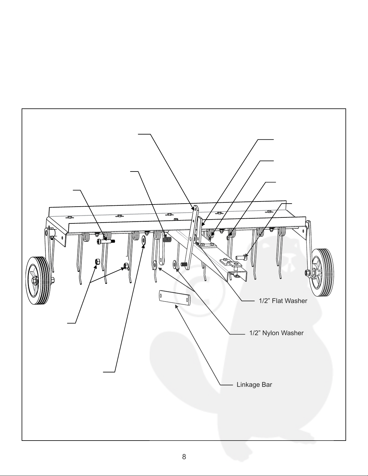
Figure 7
Lever Link
Linkage Bar
Handle Brace
Compression Spring
1/2” Nylock
Nut
1/2” x 1-3/4”
Shoulder Bolt
1/2” Flat Washer
1/2” Nylon Washer
3/8” Jam Nut
1/2” Flat Washer
1/2” x 1-1/4”
Hex Head Bolt
3/8” Flat Washer
7. Place the 1/2” Nylon Washer onto the threaded stud on the Lever Link, insert the stud into one of the holes
of the Linkage Bar, and secure with a 1/2” Nylock Nut (Tighten all the way until snug then back off 1/2 a turn).
Insert 1/2” x 1-1/2” Hex Head Bolt into the Axle Link, place a 1/2” Nylon Washer on to the bolt, insert the bolt into
the rear hole of the Linkage Bar, secure a 1/2” Nylock Nut. Insert the 1/2” x 1-3/4” Shoulder Bolt into a 1/2” Flat
Washer, the Compression Spring, another 1/2” Flat Washer. Insert the bolt into the larger center hole of the Lever
Link, followed by a 1/2” Flat Washer. Insert the bolt into the one hole on the vertical portion of the Handle Brace,
and secure with a 3/8” Jam Nut. See Figure 7.
Linkage Bar
1/2” Nylon Washer
1/2” Flat Washer
1/2” x 1-1/4”
Hex Head Bolt
3/8” Jam Nut
3/8” Flat Washer
Handle Brace
Lever Link
Compression Spring
1/2” x 1-3/4”
Shoulder Bolt
1/2” Nylock
Nut
1/2” Flat Washer
Figure 7

Figure 8
5/16” Jam Nylock Nut
5/16” x 2_1/4”
Hex Head Bolt
Lever Link
5/16” x 1-3/4”
Hex Head Bolt
5/16” Nylock Nut
Handle
Handle Grip
9
8. Attach the Handle Grip to the Handle. Insert the 5/16” x 1-3/4” Hex Head Bolt in to the top hole in the Handle
(from the right side as us are facing the unit), then through the top hole of the Lever Link and secure with a 5/16”
Nylock Nut. Attach the 5/16” Nylock Jam Nut to the 5/16” x 2-1/4” Hex Head Bolt (leaving about 1/2” spacing
at the top). Insert the bolt into the second hole of the Handle (from the right as you are facing the unit), and the
Lever Link, then secure with a 5/16” Hex Head Nut. See Figure 8.
5/16” Jam Nylock Nut
5/16” x 1-3/4”
Hex Head Bolt
5/16” x 2_1/4”
Hex Head Bolt
Handle
Handle Grip
5/16” Nylock Nut
Lever Link
Figure 8
10
Operation
Raising/Lowering the Dethatcher
1. To raise the dethatcher for transport lift up the back
until the tines are no longer in contact with the ground.
2. To lower the dethatcher for operation, move the
Handle to the down position.
3. Do not use more than 70 lbs ballast on the Base.
Using the Dethatcher
Regular removal of thatch is a critical step for the
maintenance of a healthy lawn. Thatch is a layer of
stems, clippings, runners, roots, and leaves that has
not decayed. Excessive thatch prevents air, water,
and fertilizer from reaching the roots. The dethatcher
will effectively dislodge excessive thatch from your
lawn. Use your dethatcher in the mid-tolate Spring
and/or in early Fall.
1. Your grass should be less than 3” tall for proper tine
action.
2. Start with the tractor in low gear. Vary the forward
speed to determine the best speed for maximum
performance.
3. When in use, all tines on the dethatcher should
bend to the back and “ip” the thatch forward as it is
pulled.
4. Use a crisscross pattern to achieve the most even
removal of thatch.
5. On slopes, always operate in an up and down
direction only.
6. Avoid extremely sharp turns.
7. Not for use with Zero Turn Radius Mowers.
Maintenance
1. Before each use check all nuts and bolts for
tightness.
2. Clean after each use to prevent rust. The key to
years of trouble-free service is to keep your dethatcher
clean and dry.
3. If rust should develop, sand lightly and then paint
area with enamel.
4. Periodically check all moving parts for free
movement and if necessary, lubricate with oil.
Storage
1. Be careful to store your dethatcher with the tines
pointed towards the oor or a wall. Tines are sharp
and can cause considerable damage.
2. Always store in a dry area, and coat exposed
metal with light oil when not in use.
Parts and Support
Please do not return this product to the
store prior to contacting Precision.
At Precision Products Inc. our goal is to deliver quality,
value and outstanding service. If for any reason our
product does not meet your expectations please
contact us and we will take care of any problem you
may have with this unit.
When ordering replacement parts please have the
model number, part description and part number,
inspector number and date on box available so that
we can best serve you.
1 (800) 225-5891
www.precisionprodinc.com
Precision Products Inc.

1
2
3
4
5
6
7
8
9
10
11
12
13
14
15
16
17
18
19
20
21
22
23
24
25
26
27
28
29
30
31
32
33
34
35
36
37
Ref. Ref.Qty. Qty.Part# Part#Description Description
1
1
1
1
1
2
1
1
9
1
2
1
2
1
1
1
2
11
5
1
1
1
6
2
1
9
14
2
14
1
2
4
6
14
1
1
2
5592GY
5561GY
1243GY
5576GY
5593GY
5568GY2
4263G
4240G
4005GY
5564GY
3150
30421
4271
5583
1752
2051
4014
3738
1248
4011
1840
4272
1506
5589
1278
2172
1044
3414
1276
1042
4324
4327
1749
1275
5590
5591
4295
Base Plate
Tow Bar
Clevis Plate
Handle
Axle Assembly
Wheel Bracket
Lever Link
Link Bar
Tine
Handle Brace
Wheels
Handle Grip
1/2”x 3” Hex Head Bolt
1/2”x 1-1/2” Hex Head Bolt
5/16”x 2-1/4” Hex Head Bolt
5/16”x 1-3/4” Hex Head Bolt
5/16”x 1-1/2” Hex Head Bolt
5/16”x 1” Hex Head Bolt
5/16”x 3/4” Hex Head Bolt
1/2”x 1-3/4” Shoulder Bolt
1/2”x 3-1/2” Clevis Pin
Compression Spring
1/2”Flat Washer
1/2”Nylon Washer
3/8”Flat Washer
5/16”Fender Washer
5/16”Flat Washer
1/2”Lock Washer
5/16”Lock Washer
#14 Hitch Pin Clip
1/2”Jam Nut
1/2”Nylock Nut
5/16”Nylock Nut
5/16”Hex Head Nut
3/8”Nylock Jam Nut (thin)
5/16”Nylock Jam Nut (thin)
1/2”x 1” Spacer
11
Manufacture’s Limited Warranty for Pull Behind Accessories
The limited warranty set forth below is given by Preci-
sion Products Incorporated with respect to new mer-
chandise purchased and used in the United States, its
possessions and territories.
Precision Products Incorporated warranties the
product(s) listed against defects in material and work-
manship, and will at our option, repair or replace, free
of charge, any part found to be defective in materials
or workmanship. This limited warranty shall only ap-
ply if this product has been assembled, operated, and
maintained in accordance with the owner’s manual
furnished with the product, and has not been sub-
jected to misuse, abuse, neglect, accident, improper
maintenance, alteration, vandalism, theft, re, water,
or damage because of other peril or natural disaster.
Normal wear parts or components thereof are subject
to separate terms as follows: All normal wear parts or
component failures will be covered on the product for
a period of one year. Parts found to be defective within
the warranty period will be replaced at our expense.
Our obligation under this warranty is expressly limited
to the replacement or repair, at our option, of parts
found to be defective in material and workmanship.
Contacting Service
Warranty parts replacements are available, ONLY WITH
PROOF OF PURCHASE, through our Customer Service
Department.
Call 1 (800) 225-5891
This limited warranty does not provide coverage in
thefollowing cases:
1. Routine maintenance items such as lubricants and
lters.
2. Normaldeteriorationoftheexteriornishduetouse
or exposure.
3. Transportation and/or labor charges.
No implied warranty, including any implied warranty
of merchantability of tness for a particular purpose,
applies after the applicable period of expressed writ-
ten warranty above as to the part as identied below.
No other expressed warranty, whether written or oral,
except as mentioned above, given by any person or
entity, including a dealer or retailer, with respect to any
product, shall bind Precision Products Inc. during the
period of the warranty, the exclusive remedy is repair
or replacement of the product as set forth above. The
provisions as set forth in this warranty provide the sole
and exclusive remedy arising from the purchase
Precision Products Inc. will not be liable for incidental
or consequential loss or damage including, without
limitation, expenses incurred for substitute or replace-
ment lawn care services, or for rental expenses to tem-
porarily replace a warranted product.
Some states do not allow the exclusion or limitation of
incidental or consequential damages, or limitations on
how long an implied warranty lasts, so the above ex-
clusions or limitations may not apply to you.
During the warranty period, the exclusive remedy is
replacement of the part. In no event shall recovery of
any kind be greater that the amount of the purchase
price of the product sold. Alteration of safety features
of the product shall void this warranty. You assume the
risk and liability for loss, damage, or injury to you and
your property and/or to others and their property aris-
ing out of the misuse or inability to use this product.
This limited warranty shall not extend to anyone other
than the original purchaser or to the person for whom
it was purchased as a gift.
Local Law to this Warranty
This limited warranty gives you specic legal rights,
and you may also have other rights which vary from
state to state.
Warranty Period
The warranty period stated below begins with the
Proof of Purchase. Without the proof of purchase, the
warranty period begins from the date of manufacture.
Product Warranty Period
The warranty period for this product is as follows: All
parts are covered for 1 year.
12

Handleiding | PA500 | 40” Aanhang-gazonverluchter
Inhoud van de handleiding
Veiligheidsinstructies..................................................... 2
Montage ............................................................................. 4-9
Bediening........................................................................... 10
Onderhoud........................................................................ 10
Onderdelen ....................................................................... 2-3
Garantie .............................................................................. 12
Uw nieuwe gazonverluchter
Gefeliciteerd met uw aankoop van een nieuwe Pre-
cision Products, Inc. Gazonverluchter. Uw gazonver-
luchter werd ontworpen en gemaakt om u het meest
betrouwbare en best presterend product te bieden.
Indien u een probleem ondervindt dat u niet
kan oplossen, contacteer dan gratis onze
bekwame en behulpzame klantendienst
1 (800) 225-5891.
Waarschuwing: Lees alle regels en instructies voor een veilige toepassing.
Form. nr. 5570(Rev. 10/11)

Regels voor veilig gebruik
Lees de handleiding van uw tractor en houd u aan de veiligheidsregels voor slepen.
• Lees de handleiding van uw tractor en houd u aan de veiligheidsregels voor slepen. .
• Laat kinderen nooit het sleepvoertuig bedienen. Laat geen volwassenen de tractor bedienen zonder dat ze de handleiding hebben gelezen
of zonder dat ze voldoende instructies hebben gekregen. .
• Laat niemand rijden met of zitten op de installatie tijdens gebruik.
• Hou alle mensen en dieren op een veilige afstand.
• Draag altijd stevige schoenen. Draag geen loszittende kledingsstukken die vast kunnen raken in de bewegende onderdelen.
• Deze unit kan scherpe uiteindes hebben. Met zorg behandelen.
• Houd uw ogen en gedachten bij uw tractor/hulpstuk en de zone die moet worden behandeld. Laat u niet aeiden.
• Wees alert voor gaten in het terrein en andere verborgen gevaren.
• Het remmen en de stabiliteit van de tractor kan worden beïnvloed door het aanhangen van deze unit. Let op veranderende omstandigheden
op hellingen. Kijk in de veiligheidsregels in de handleiding van uw tractor betreende de veilige handeling op hellingen. Blijf weg van steile
hellingen.
• Ga op een helling steeds op en neer, nooit dwars over het oppervlak van de helling.
• De uitrusting moet worden gebruikt op laag tempo op ruwe terreinen, langs beekjes en sloten en op hellingen om omslaan of verlies van
controle te vermijden.
• Begin altijd met de aandrijving in de eerste (lage) versnelling en de motor op lage toeren, versnel geleidelijk aan in de mate dat de omstan-
digheden het toelaten.
• Houd de tractor en het hulpstuk in goede staat en houd de veiligheidsmiddelen op hun plaats.
• Laat alle moeren, bouten en schroeven vastgedraaid om zeker te zijn dat het apparaat veilig is voor gebruik.
• De tractor en het hulpstuk moeten worden gestopt en gecontroleerd op schade wanneer een vreemd object wordt geraakt. Enige schade
moet worden hersteld voor opnieuw op te starten en verder te gaan met het gebruik van het apparaat.
• Volg de onderhoudsinstructies zoals beschreven in deze handleiding.
• Ga niet sneller dan 4-6 km per uur.
Inhoud van de doos
2

Inhoud van de verpakking met ijzerwaren
34
2726
22
2825
15
16 17
1918
20
21
23 24
13
14
31 33
32
3029
35 36 37
1
2
3
4
5
6
7
8
9
10
11
12
13
14
15
16
17
18
19
20
21
22
23
24
25
26
27
28
29
30
31
32
33
34
35
36
37
Ref. Ref.Aant. Aant.Omschrijving Omschrijving
1
1
1
1
1
2
1
1
9
1
2
1
2
1
1
1
2
11
5
1
1
1
6
2
1
9
14
2
14
1
2
4
6
14
1
1
2
Basisplaat
Sleepstang
Vorkplaat
Hendel
Asmontage
Wielsteun
Hefboomverbindingsstuk
Verbindingsplaat
Tand
Handvatsteun
Wielen
Handvat
½”x 3” zeskantbout
1/2”x 1-1/2” zeskantbout
5/16”x 2-1/4” zeskantbout
5/16”x 1-3/4” zeskantbout
5/16”x 1-1/2” zeskantbout
½”x 1” zeskantbout
5/16”x 3/4” zeskantbout
1/2”x 1-3/4” borstbout
1/2”x 3-1/2” vorkbout
Spanveer
1/2”vlakke sluitring
½”nylon sluitring
3/8”vlakke sluitring
5/16”Fender-sluitring
5/16”vlakke sluitring
1/2”borgring
5/16”borgring
# 14 borgveer
½”kroonmoer
1/2”nylock-moer
5/16”nylock-moer
5/16”zeskantmoer
3/8”nylock-kroonmoer (dun)
5/16”nylock-kroonmoer (dun)
1/2”x 1” tussenstuk
3

Montage-instructies
(2) 1/2” moersleutel
(2) 3/4” moersleutels
(2) 9/16” moersleutels
Uit de verpakking halen
Verwijder alle onderdelen en materiaal uit de verpakking. aan de hand van de illustraties op pagina 2 en 3.
1. Plaats de basisplaat op een vlakke ondergrond zodat de voorkant van u weg wijst (de voorkant zal drie
boutopeningen in het midden hebben). Plaats de korte kan van de as in de asopening aan uw linkerzijde. Schuif
de sleepstang op de as. Schuif de as in de asopening aan de rechterzijde van de basisplaat. Zie afbeelding 1.
Figure 1
Tow Bar
Front
Base Plate
Axle
1/2” x 1-1/4”
Hex Head Bolt
Afbeelding 1
4
As
Basisplaat
Voorzijde
Sleepstang
1/2” x 1-1/4”
Hex Head Bolt

Figure 2
5/16” Lock Washer
Base Plate
5/16” x 3/4” Hex Head Bolt
5/16” Flat Washer
Tow Bar
5/16” Hex Head Nut
5/16” x 1” Hex
Head Bolt
Base Plate
Tine
5/16” Fender Washer
5/16” Flat Washer 5/16” Lock Washer
5/16” Hex Head Nut
Figure 3
2. Plaats de drie achterste openingen in de sleep staan op dezelfde hoogte als de overeenkomstige openingen
op de basisplaat. Plaats een 5/16” x 3/4” kruiskopbout in een van de eindgaten van de basisplaat en vervolgens
door de overeenkomstige opening in de sleepstang. Plaats een 5/16” vlakke sluitring op de bout, gevolgd door
een 5/16” borgring, maak vervolgens vast met een 5/16” hexagonale moer. Herhaal het proces voor de overige
2 openingen. Zie afbeelding 2.
3. Plaats een 5/16” x 1” zeskantbout in een van de negen overblijvende openingen in de basisplaat, plaats een
5/16” Fender-sluitring op de bout, gevolgd door een 5/16” vlakke sluitring en een 5/16” borgring. Maak een 5/16”
hexagonale moer losjes vast. Herhaal het proces voor de overige acht openingen. Schuif een tand tussen een
Fender-sluitring en de basisplaat, maak vast met een hexagonale moer, herhaal voor de overige acht tanden.
Zie afbeelding 3.
Afbeelding 3
Afbeelding 2
5
5/16” zeskantmoer
++5/16” borgring
5/16” vlakke sluitring
Sleepstang
5/16” x 3/4” zeskantbout
Basisplaat
5/16” zeskantmoer
5/16” borgring
Tand
Basisplaat
5/16” Fender-sluitring
5/16” vlakke sluitring
½” x 1” zeskant-
bout

Figure 4
Wheel Bracket
1” x 1/2” Spacer
Axle
5/16” x 1-1/2” Hex Head Bolt
5/16” Nylock Nut
Figure 5
1/2” Nylock Nut
1/2” Flat Washer
1/2” x 3” Hex
Head Bolt
Wheel Bracket
Wheel
1/2” Lock Washer
1/2” Jam Nut
4. Plaats een 1” x 1/2” tussenstuk op de as, gevolgd door een wielsteun. Plaats de opening van de wielsteun op
één lijn met het gat in de as. Plaats een zeskantbout in de openingen van de wielsteun en as. Maak vast met
een 5/16” Nylon-moer. Herhaal dit proces op de andere kant. Zie afbeelding 4.
5. Plaats een 1/2” vlakke sluitring op een 1/2” x 3” kruiskopbout, gevolgd door een wiel en vervolgens nog een
1/2” vlakke sluitring en maak vast met een 1/2” Nylock-moer (niet te vast doen, anders kan het wiel niet draaien)
Plaats deze montage in de opening van de wielsteun, plaats vervolgens een 1/2” vlakke sluitring op de bout en
maak het vast met een 1/2” kroonmoer. Herhaal dit proces op de andere kant. Zie afbeelding 5.
Figure 5
Afbeelding 4
5/16” x 1-1/2” zeskantbout
As
1/2” nylock-moer
1/2” kroonmoer 1/2” vlakke sluitring
1/2” x 3”
kruiskop- bout
Wiel-
Wielsteun
1/2” borgring
1” x 1/2” tussenstuk
5/16” nylock-moer
Wielsteun
6

7
Figure 6
Clevis Pin
Clevis Plate
5/16” Hex
Head Nut
5/16” Flat Washer
5/16” Lock Washer
5/16” x 3/4” Hex
Head Bolt
Handle Brace
5/16” x 1” Hex Head Bolt
5/16” Nylock
Nut
Tow Bar
Hitch Pin Clip
6. Plaats de twee openingen van de sleepstang en het handvat zoals weergegeven. Plaats een 5/16” x 1/4”
zeskantbout in één van de openingen in het hendel stop en vervolgens in de overeenkomstige opening in de
sleepstang, plaats een 5/16” vlakke sluitring op de bout en maak het vast met een 5/16” Nylock-moer. Herhaal
het proces voor de volgende opening. Plaats een 5/16” x 3/4” kruiskopbout in de 2 kleinere gaatjes op de
vorkplaat en vervolgens in de overeenkomstige opening in de sleepstang, plaats een 5/16” vaste sluitring op de
bout en maak het vast met een 5/16” hexagonale moer. Herhaal het proces voor de volgende opening. Steek de
vorkbout door de grotere opening aan de voorzijde van de vorkplaat en door de opening van de sleepstang en
maak het vast met een borgveer. Zie afbeelding 6.
½” x 1” zeskantbout
Handvatsteun
5/16” x 3/4” kruiskop-
bout
Vorkbout
Vorkplaat
Sleepstang
Borgveer
Afbeelding 6
5/16” zes-
kantmoer
5/16” nylock-
moer
5/16” borgring
5/16” vlakke sluitring

8
Figure 7
Lever Link
Linkage Bar
Handle Brace
Compression Spring
1/2” Nylock
Nut
1/2” x 1-3/4”
Shoulder Bolt
1/2” Flat Washer
1/2” Nylon Washer
3/8” Jam Nut
1/2” Flat Washer
1/2” x 1-1/4”
Hex Head Bolt
3/8” Flat Washer
7. Plaats de 1/2” Nylon-sluitring op de draadstang op het hefboomverbindingsstuk, plaats de stang in één van de
openingen in de verbindingsplaat en maak vast met een 1/2” Nylock-moer (Draai aan tot ze volledig vast zit en
draai dan een halve draai terug). Plaats een 1/2” x 1-1/2” in de zeskantbout in de asverbinding, plaats een 1/2”
Nylon-sluitring op de bout, plaats de bout in de achterste opening in de verbindingsplaat, maak vast met een
1/2” Nylock-moer. Plaats een 1/2” x 1-3/4” borstbout in een 1/2” vlakke sluitring, de spanveer en nog een 1/2”
vlakke sluitring. Plaats de bout in de grotere opening in het midden van de verbindingsplaat, gevolgd door een
1/2” vlakke sluitring. Plaats de bout in de ene opening op het verticale deel van de handvatsteun en maak vast
met een 3/8” kroonmoer. Zie afbeelding 7.
Verbindingsplaat
½” nylon sluitring
1/2” vlakke sluitring
1/2” x 1-1/4”
kruiskopbout
3/8” kroonmoer
3/8” vlakke sluitring
Handvatsteun
Hefboomverbindingsstuk
Spanveer
1/2” x 1-3/4”
borstbout
1/2” nylock-
moer
1/2” vlakke sluitring
Afbeelding 7
Other manuals for TA500
1
Table of contents
Languages:
Other Precision Lawn And Garden Equipment manuals


